


SONY BETAMAX SL-T30ME COLOR 3+1 SYSTEM Magnetic tape loading apparatus:
In a magnetic recording and/or reproducing apparatus of the type having a
cylindrical tape guide drum with at least one rotary magnetic head
adapted to move in a circular path substant ially coinciding with the
outer circumferential surface of said drum and a tape cassette holder
positioned in front of the guide drum for receiving a tape cassette
containing a magnetic tape, an automatic tape loading and unloading
device for wrapping a portion of the tape about the guide drum includes a
rotatable support ring extending around the guide drum and being
rotatable in a plane that is inclined with respect to a plane passing
through the tape in the tape cassette; a tape drawing mechanism for
withdrawing a loop of tape from the cassette to a predetermined position
adjacent the guide drum; a first tape guiding assembly adapted to ride
along an arcuate guide rail surrounding a first portion of the outer
circumferential surface of the guide drum and actuable by a guide pin on
the support ring for wrapping the loop of tape about the first portion
of the outer circumferential surface of the tape guide drum as the
support ring rotates thereabout; and a second tape guiding assembly
including a tape engaging pin mounted on the support ring for
successively wrapping the loop of tape about a contiguous second portion
of the outer circumferential surface of said tape guide drum upon
completion of operation of the first tape guiding assembly.
ially coinciding with the
outer circumferential surface of said drum and a tape cassette holder
positioned in front of the guide drum for receiving a tape cassette
containing a magnetic tape, an automatic tape loading and unloading
device for wrapping a portion of the tape about the guide drum includes a
rotatable support ring extending around the guide drum and being
rotatable in a plane that is inclined with respect to a plane passing
through the tape in the tape cassette; a tape drawing mechanism for
withdrawing a loop of tape from the cassette to a predetermined position
adjacent the guide drum; a first tape guiding assembly adapted to ride
along an arcuate guide rail surrounding a first portion of the outer
circumferential surface of the guide drum and actuable by a guide pin on
the support ring for wrapping the loop of tape about the first portion
of the outer circumferential surface of the tape guide drum as the
support ring rotates thereabout; and a second tape guiding assembly
including a tape engaging pin mounted on the support ring for
successively wrapping the loop of tape about a contiguous second portion
of the outer circumferential surface of said tape guide drum upon
completion of operation of the first tape guiding assembly. 1. In a magnetic
recording and/or reproducing apparatus of the type having a cylindrical
tape guide drum with at least one rotary magnetic head adapted to move
in a circular path substantially coinciding with the outer
circumferential surface of said drum, and holder means spaced from said
guide drum for receiving tape supply means containing a magnetic tape,
tape loading and unloading means comprising a support member
extending around said guide drum and being rotatable in a plane that is
inclined with respect to a plane passing through said tape in said tape
supply means; first tape guiding means movable in a plane which is inclined relative to said plane of rotation of said support member and being actuable by said support member for wrapping a portion of said tape about a first portion of the outer circumferential surface of said tape guide drum; and
second tape guiding means actuable by said support member and acting on said tape following the wrapping thereof about said first portion of the outer circumferential surface for further wrapping said portion of said tape about a contiguous second portion of the outer circumferential surface of said tape guide drum.
2. An apparatus according to claim 1; in which said support member is in the form of a ring rotatable about its center which is eccentrically located with respect to the axis of said guide drum in the direction toward said tape supply means so as to provide a relatively large clearance between said ring and said guide drum at the side of the latter facing toward said tape supply means.
3. An apparatus according to claim 2; further comprising at least one fixed magnetic head spaced from said guide drum within said clearance and being engaged by said tape when said tape is wrapped about at least a portion of the outer circumferential surface of said guide drum.
4. An apparatus according to claim 1; further comprising tape drawing means for withdrawing a loop of said tape from said tape supply means to a predetermined position.
5. An apparatus according to claim 4; further comprising a chassis, and in which said tape drawing means includes arm means pivoted at one end on said chassis and a tape guiding member extending from the other end of said arm means for withdrawing said loop of tape from said tape supply means to said predetermined position.
6. In a magnetic recording and/or reproducing apparatus of the type having a chassis, a cylindrical tape guide drum with at least one rotary magnetic head adapted to move in a circular path substantially coinciding with the outer circumferential surface of said drum, and holder means spaced from said guide drum for receiving tape supply means containing a magnetic tape, tape loading and unloading means comprising a support member extending around said guide drum
and being rotatable in a plane that is inclined with respect to a plane
passing through said tape in said tape supply means; first tape guiding means actuable by said support member for wrapping a portion of said tape about a first portion of the outer circumferential surface of said tape guide drum;
second tape guiding means actuable by said support member for successively wrapping said portion of said tape about a contiguous second portion of the outer circumferential surface of said tape guide drum; and
tape drawing means including arm means having a first pivotal arm pivoted at one end on said chassis and a second tape engaging arm pivoted at an intermediate point thereon at the other end of said first pivotal arm, and a tape guiding member extending from one end of said second tape engaging arm for withdrawing a loop of said tape from said tape supply means to a predetermined position.
7. An apparatus according to claim 6; in which said tape drawing means further includes drive means for rotating said arm means so as to withdraw said loop of tape from said tape supply means to said predetermined position, said drive means including planetary gear means having at least one sun gear and a planet gear adapted to rotate about said at least one sun gear, and spring means for rotating said arm means in response to rotation of said planet gear about said at least one sun gear.
8. An apparatus according to claim 7; in which said planetary gear means includes a shaft secured to said chassis and two sun gears mounted on said shaft in meshing relation with said planet gear; and said drive means further includes cam lever means for preventing rotation of one of said sun gears and said support member wher
eby rotation of the other of said sun gears causes said planet gear
to rotate thereabout, and plate means for mounting said planet gear
about said shaft in meshing relation with said two sun gears.
9. An apparatus according to claim 8; in which said spring means includes a tension spring connected between said plate means and said first pivotal arm of said arm means whereby rotation of said planet gear about said other of said sun gears results in said tension spring rotating said arm means so as to withdraw said loop of tape from said tape supply means to said predetermined position.
10. An apparatus according to claim 9; in which said arm means further includes a link pin mounted at the other end of said second tape engaging arm, and said tape drawing means further includes a guide plate having an arcuate slot therein in which said link pin rides during rotation of said arm means to cause said second tape engaging arm to rotate relative to said first pivotal arm so as to position said tape at said predetermined position.
11. In a magnetic recording and/or reproducing apparatus of the type having a cylindrical tape guide drum with at least one rotary magnetic head adapted to move in a circular path substantially coinciding with the outer circumferential surface of said drum, and holder means spaced from said guide drum for receiving tape supply means containing a magnetic tape, tape loading and unloading means comprising a support member extending around said g
uide drum
and being rotatable in a plane that is inclined with respect to a plane
passing through said tape in said tape supply means; first tape guiding means actuable by said support member for wrapping a portion of said tape about a first portion of the outer circumferential surface of said tape guide drum;
second tape guiding means actuable by said support member for successively wrapping said portion of said tape about a contiguous second portion of the outer circumferential surface of said tape guide drum; and
an arcuate guide rail positioned about said first portion of the outer circumferential surface of said guide drum and on which said first tape guiding means is adapted to ride for wrapping said portion of said tape about said first portion of the outer circumferential surface of said tape guide drum.
12. An apparatus according to claim 11; in which said first tape guiding means includes movable plate means adapted to ride along said guide rail, pivotal plate means pivotally mounted on said movable plate means, and tape engaging means pivotally mounted on said pivotal plate means for engaging said portion of said tape as said movable plate means rides along said guide rail.
13. An apparatus according to claim 12; in which said tape engaging means includes a tape engaging pin adapted to be moved between a lower inoperative position below said tape and a raised operative position for engaging said tape as said movable plate means rides along said guide rail, spring means for urging said tape engaging pin to said raised operative position, and an engaging member for urging said tape engaging pin to said lower inoperative position when said tape engaging means is inoperative.
14. An apparatus according to claim 13; in which said pivotal plate means includes guide lever means extending radially inward toward said support member, and said support member has guide arm means secured thereto for contacting said guide lever means as said support member is rotated about said guide drum, whereby said first tape guide means rides along said guide rail to wrap said portion of said tape about said first portion of the outer circumferential surface of said guide drum.
15. An apparatus according to claim 1; in which said second tape guiding means includes a tape engaging pin secured to said support member for engaging said portion of said tape during completion of operation of said first tape guiding means and upon continued rotation of said support member whereby said portion of said tape is wrapped about said contiguous second portion of the outer circumferential surface of said tape guide drum.
16. An apparatus according to claim 1; in which said tape guide drum has a tape edge guide formed on said outer circumferential surface in a plane which is inclined in respect to the plane of said circular path of the head and being engageable by an edge of the tape wrapped about said circumferential surface, and said plane in which the first tape guiding means is movable is approximately parallel with said plane of the tape edge guide.
Description:
BACKGROUND OF THE INVENTION1. Field of the Invention
This invention rel
ates generally to magnetic recording and reproducing
apparatus, such as, video tape recording and reproducing apparatus
(VTR), and more particularly, is directed to an improved automatic tape
loading and unloading device for such apparatus. 2. Description of the Prior Art
Existing video tape recording and reproducing apparatus generally comprise a tape guide drum having a rotary magnetic head assembly associated therewith to record or reproduce video signals on a magnetic tape which is usually wound on supply and take-up reels with the tape beneath such reels being wrapped about a portion of the circumferential surface of the drum and being driven by a cooperating capstan and pinch roller and by suitable rotation of the take-up reel. In preparing such a video tape recording and reproducing apparatus for operation, the tape extending between the supply and take-up reels, which are preferably contained in a cassette, must be wrapped about at least a portion of the drum circumference so that the tape will be guided thereby with respect to the rotary magnetic head assembly.
One type of previously
proposed automatic tape loading and unloading device for wrapping the
tape extending between the supply and take-up reels about a portion of
the circumferential surface of the drum is disclosed in detail in U.S.
Pat. No. 3,821,805, issued June 28, 1974, having a common assignee
herewith and includes a rotatable support member, in the form of a ring,
extending around the guide drum in a plane that is inclined with
respect thereto. The support ring includes a tape engaging member, such
as a guide pin, extending from a rotatable arm supported by the support
ring, the guide pin projecting upwardly from the support ring so as to
extend into an opening of the cassette for engagement with the tape
therein when the ring is an inactive or starting positon. The tape
engaging member or pin draws a loop of tape from the cassette and wraps
one side of the tape loop around the guide drum upon rotation of the
ring to an operative position during a tape loading operation. However, the guide drum and support ring are both inclined at different angles with respect to the cassette holder. Thus, the tape engaging member or guide pin secured to the support ring is also inclined with respect to the cassette holder and the tape positioned therein. As a result of such inclination of the guide pin, the tape engaged thereby tends to shift upwardly towards the free end of the guide pin, that is, in the widthwise direction of the tape, during the loading operation of the tape on the tape guide drum. This is particularly applicable when the guide pin is comprised of a rotatable roller which is provided for smooth loading of the tape about the guide drum. Conventionally, a guide pin flange has been provided at the upper or free end of the guide pin for retaining the tape on the guide pin during the loading operation. However, since the tape has a tendency to shift upwardly on the guide pin, the tape is often bunched or creased against the flange, causing possible damage to the tape or to any recording made therein during operation of the magnetic recording and/or reproducing apparatus.
OBJECTS AND SUMMARY OF THE INVENTION
Accordingly, it is an object of this invention to provide an automatic tape loading and unloading device for a magnetic recording and/or reproducing apparatus that avoids the above-described difficulties encountered with the prior art.
More particularly, it is an object of this invention to provide an automatic tape loading and unloading device for a magnetic recording and/or reproducing apparatus which employs a magnetic tape contained in a cassette or cartridge.
Another object of this invention is to provide an automatic tape loading and unloading device which automatically and smoothly wraps a magnetic tape about a tape guide drum in a helical scan magnetic record
ing and/or
reproducing apparatus without bunching or creasing the tape. Still another object of this invention is to provide an automatic tape loading and unloading device having a rotatable support ring extending about a guide drum and first and second tape guide assemblies actuable by the support ring for successively wrapping a magnetic tape about first and second circumferential portions of the tape guide drum.
In accordance with an aspect of this invention, an automatic tape loading and unloading device is provided for use in a magnetic recording and/or reroducing apparatus of the type having a cylidrical tape guide drum with at least one rotary magnetic head which moves in a circular path substantially coinciding with the outer circumferential surface of the drum, and a cassette holder spaced from the guide drum for receiving a cassette or cartridge containing a magnetic tape, for example, wound about and extending between supply and take-up reels in the cassette or cartridge. The tape loading and unloading device includes a support member, such as a rotatable support ring, extending around the guide drum and being rotatable in a plane that is inclined with respect to a plane passing through the tape in the cassette or cartridge. The device further includes a first tape guiding assembly actuable by the support ring for helically wrapping a loop of the tape about a first portion of the circumferential surface of the tape guide drum, for example, along a first half of eventually covered surface of the tape guide drum, and a second tape guiding assembly also actuable by the support ring for successively wrapping the aforesaid loop of the tape a contiguous second portion of the circumferential surface of the tape guide drum so as to complete the loading of the magnetic tape to its operative position.
In a preferred embodiment, the first ta
pe guiding assembly includes a
first tape engaging member which rides on an arcuate guide rail
extending around the guide drum along the first portion of the
circumferential surface of the drum. The first tape guiding assembly is
caused to ride along the arcuate guide rail by an engaging pin on the
rotatable support ring as the latter rotates about the guide drum. The
second tape guiding assembly includes a second tape engaging member
disposed on the rotatable support ring for engaging the tape after the
first tape engaging member has completed its movement along the arcuate
guide rail. The second tape engaging assembly thus engages the tape
during the remaining rotation of the support ring for wrapping the tape
about a second contiguous portion of the circumferential surface of the
tape guide drum. The above, and other, objects, features and advantages of the invention, will be apparent in the following detailed description of an illustrative embodiment of the invention which iis to be read in connection with the accompanying drawings.
BRIEF DESCRIPTION OF THE DRAWINGS
FIG. 1 is a schematic top plan view of a magnetic recording and/or reproducing apparatus provided with a tape loading and unloading device according to the prior art;
FIG. 2 is a side elevational view of a portion of the apparatus of FIG. 1;
FIG. 3 is a schematic top plan view of an automatic tape loading and unloading device according to this invention for use in a magnetic recording and/or reproducing apparatus, in which the automatic tape loading and unloading device is in its inoperative position;
FIG. 4 is a side elevational view of the automatic tape loading and unloading device of FIG. 3;
FIG. 5 is a perspective view illustrating the positional relationship between the tape guide drum and the arcuate guide rail in the tape loading and unloading device of FIG. 3;
FIG. 6 is an enlarged perspective view of the first tape guiding assembly of the tape loading and unloading device of FIG. 3;
FIG. 7 is an enlarged top plan view of the first tape guiding assembly of FIG. 6;
FIG. 8 is a side elevational view of the first tape guiding assembly of FIG. 6 in its operative position in which the positional relationship between the first tape guiding assembly, the tape guide drum and the support ring is shown;
FIG. 9 is a top plan view of the automatic tape loading and unloading device of FIG. 3 in which a loop of tape has been withdrawn from the cassette housing;
FIG. 10 is a side elevational view of the first tape guiding assembly of FIG. 6 in its inoperative position;
FIG. 11 is an enlarged top plan view of a portion of the tape drawing mechanism of the tape loading and unloading device of FIG. 3 illustrating the positional relationship thereof at the start of rotation of the support ring;
FIG. 12 is a top plan view of the tape loading and unloading device of FIG. 3, illustrating the actuation of the first tape guiding assembly by the support ring;
FIG. 13 is a top plan view of the tape loading and unloading device of FIG. 3, illustrating the final position of the first tape guiding assembly;
FIG. 14 is an enlarged top plan view of the first tape guiding assembly at its position shown in FIG. 13;
FIG. 15 is a top plan view of the tape loading and unloading device of FIG. 3 upon completion of the tape loading operation.

Referring to the drawings in detail, and initially to FIG. 1 thereof, it will be seen that, in the prior art magnetic recording and/or reproducing apparatus there illustrated, a tape cassette 3 is provided which includes supply and take-up reels rotatably contained within cassette 3 and having a magnetic tape 4 wound thereon. A loop of magnetic tape 4 is drawn out from cassette 3 and helically wrapped about at least a portion of the outer circumferential surface 6 of a cylindrical tape guide drum 5 having a circumferential slot or gap (not shown) and having one or more rotary magnetic heads (not shown) which are moved along the slot or gap, that is, in a circular path substantially coinciding with the outer circumferential surface of tape guide drum 5. A mechanism for wrapping tape 4 about gude drum 5 includes an annular support member 1, such as a support ring, which is rotatably supported for rotation about guide drum 5 in a circular or arcuate path and is eccentrically positioned with respect thereto. An upstanding tape guiding pin 2 is mounted on the upper surface of support ring 1 through, for example, a pivotal arm (not shown), for withdrawing tape 4 from tape cassette 3 and helically wrapping the tape about the outer circumferential surface 6 of tape guide drum 5 as support ring 1 rotates in the clockwise direction as viewed in FIG. 1.
In such prior art apparatus, in order for tape 4 to be helically wrapped about outer circumferential surface 6, guide drum 5 is inclined with respect to cassette 3 (in the direction of arrow A) at a slant angle α, as shown in FIG. 2. Support ring 1 is also inclined with respect to cassette 3 (in the direction of arrow A) by a different slant angle β. It should be appreciated that the inclination of support ring 1 with respect to cassette 3 results in tape guiding pin 2 also being inclined with respect to tape cassette 3 and, more particularly, with the longitudinal direction along tape 4, as withdrawn from tape cassette 3. Consequently, during the loading operation, when tape guiding pin 2 rotates with support ring 1 so as to wrap the tape about guide drum 5, tape 4 has a tendency to move or shift toward the free end of tape guiding 2, that is, in the widthwise direction of tape 4. This is particularly applicable when tape guiding pin 2 is comprised of a rotatable roller 2a, the latter being utilized for smooth loading of the tape about guide drum 5. In other words, as roller 2a rotates about its own axis and also rotates with support ring 1, the tape tends to shift toward the free end of roller 2a. In the case where a flange 8 is provided at the free or upper end of tape guiding pin 2 (FIG. 2), the shifting movement of tape 4 results in the tape bunching or being creased, causing possible damage to the tape and/or to any recording made thereon.

The tape loading and unloading device according
to this
invention is shown to include an annular support member 12, preferably
in the form of a support ring, which is rotatably supported for rotation
about guide drum 11 in a circular or arcuate path that extends under
guide drum 1. Support ring 12 is shown to be inclined with respect to
guide drum 11 and is positioned eccentrically with respect thereto to
provide a relatively large space for accommodating a drive capstan 76
and fixed magnetic heads 96-99 which may, for example, be used for
recording and/or reproducing audio and control signals and for erasing
any previously recorded signals from the tape. The tape loading and unloading device according to this invention is further shown to include a tape drawing mechanism for withdrawing the tape 17 extending between the supply and tape-up reels of tape cassette 18 to a predetermined position when the latter is received and positioned within tape cassette holder 19. The tape drawing mechanism is comprised of a pivoted arm assembly 21 having a first pivot arm 23 pivoted at one end on chassis T by means of a fixed shaft 22 and a second tape engaging arm 24 pivotally mounted at the free end of pivot arm 23 by a pin 25. Tape engaging arm 24 is provided at one end thereof with an upstanding tape guiding pin 28 adapted to project upwardly into a recess 16 of tape cassette 18 so as to be located behind tape 17, and being operative to withdraw the tape to a predetermined end position adjacent guide drum 11. At the opposite end of tape engaging arm 24, an upstanding link pin 30 is provided, the function of which will hereinafter be described in greater detail.
Pivoted arm assembly 21 is adapted to be driven in the counterclockwise directon, as viewed in

The tape drawing mechanism for withdrawing tape 17 from tape cassette 18 to its predetermined end position adjacent guide drum 11 further includes a cam lever 47 pivotally mounted on a shaft 48 secured to chassis T with cam lever 47 being positioned between support ring 12 and shaft 22. A positioning roller 50 is secured to the free end of cam lever 47 and is adapted to mate with a corresponding notch or recess 49 formed at a predetermined position along the outer periphery of support ring 12. Cam lever 47 further includes an arcuate pressure plate 52 adapted to mate with a corresponding arcuate segmental cam 51 formed on second plate 32. It should be appreciated, as shown in FIG. 3, that when segmental cam 51 mates with arcuate pressure plate 52, positioning roller 50 is urged within notch 49 of support ring 12 for preventing the latter from rotating. Lastly, the drive mechanism for arm assembly 21 includes a fixed guide plate 29 secured to a side wall 20 of the recording and/or reproducing apparatus and having an arcuate slot 69 therein.
In operation, tape guiding pin 28 of pivoted arm assembly 21 is first positioned in recess 16 formed in tape cassette 18 so as to be positioned behind a run of tape 17 extending between the supply and take-up reels. Rotary shaft 43 is then rotated by drive motor 42 in a first loading direction so as to transmit a rotational driving force to worm gear 39 through drive belt 41 and worm 40. This results in first sun gear 33 being rotated in the clockwise direction as viewed in FIG. 3. At this time, however, segmental cam 51 of second plate 32 is positioned in mating relation with pressure plate 52 of cam lever 47. This results in positioning roller 50 being urged within notch 49 to prevent rotation of support ring 12. It should therefore be appreciated that second sun gear 34 is thereby also prevented from rotating as the result of its meshing relationship with support ring 12 through gears 44-46. Thus, since planet gear 36 meshes with both sun gears 33 and 34, the rotation of sun gear 33 alone causes planet gear 36 to rotate counterclockwise thereabout, as viewed in FIG. 3., thereby also rotating first and second plates 31 and 32 about shaft 22 through connecting rod 35. Consequently, tension spring 37 causes the rotation of first plate 31 in the counterclockwise direction, as viewed in FIG. 3, to effect swinging of pivot arm 23 and tape engaging arm 24 in the counterclockwise direction about shaft 22. This, of course, results in tape guiding pin 28 moving in an arcuate path in the counterclockwise direction, as viewed in FIG. 3, thereby tape 17 is automatically withdrawn from tape cassette 18 to its predetermined end position.
It should be appreciated that w
hile pivot arm 23 is rotated about shaft
22, tape engaging arm 24 rotates slightly about pin 25 in the direction
of arrow A (FIG. 3) due to the tensioning force of tape 17 between the
supply and take-up reels during the withdrawing operation. Accordingly,
an engaging lug or stop 68 is provided on tape engaging arm 24 adjacent
pivot pin 25 which abuts against a side edge of pivot arm 23 to prevent
tape engaging arm 24 from rotating past a position where tape engaging
arm 24 and pivot arm 23 are in orthogonal relation. This orthogonal
relation is, of course, maintained throughout much of the continued
rotation of pivoted arm assembly 21. Pivoted arm assembly 21 continues
to rotate in the counterclockwise direction, as shown by the dot-dash
action lines in
In addition, a first connecting link 26 is pivotally mounted on first plate 31 near the periphery thereof so that as this latter plate rotates in the counterclockwise direction, as viewed in FIGS. 3 and 9, connecting link 26 moves towards cassette 18. A second connecting link 80 is pivoted at
one end thereof to the free end
of first connecting link 26 and is further pivoted to chassis T at an
intermediate point thereon by a pivot pin 81. A tape tensioning pin 82
is secured to the free end of second connecting link 80. Thus, as first
and second connecting links 26 and 80 move from their positions in FIG. 3
to their respective positions in FIG. 9, tape tensioning pin 82 is
rotated counterclockwise about pivot pin 81 so as to contact tape 17
withdrawn from cassette 18 and provide a tensioning force to remove any
slack therefrom.


Referring to FIGS. 6 and 7, there are shown enlarged views of first tape guiding assembly 54 which will now be described. First tape guiding assembly 54 includes a movable plate 56 on the lower surface of which are rotatably mounted three rollers 56a, 56b and 56c positioned against the side edges of guide rail 53 and adapted to ride therealong. A pivotal plate 58 is mounted, by means of a pivot pin 57 extending through an upstanding bracket portion thereof, on movable plate 56 and is spring-biased in the clockwise direction, as viewed in FIG. 7, about pivot pin 57 by a tension spring 67 connected between the upstanding bracket portion and movable plate 56. Pivotal plate 58 carries a guide pin 56d secured to a free e
nd thereof and which is adapted to ride against the inner edge of
guide rail 53, and the upstanding bracket portion of plate 58 includes a
guide lever 61 extending radially inward toward support ring 12.
Further, a U-shaped bracket 60 is pivotally mounted by a pivot pin 59 on
an upstanding bracket 58a fixed to pivotal plate 58. Bracket 60
includes an extension arm 63 having a free end at which an upstanding
tape engaging pin 62 is fixed. It should be appreciated that, as a
result of the pivotal movement of bracket 60, tape engaging pin 62 can
be positioned in a lower inoperative position, as shown in FIG. 10, or a
raised operative position where it is engageable with tape 17, as shown
in FIG. 8. Further, pivot pin 59 is positioned at a height
substantially corresponding to the widthwise center or median of tape
17, as represented by line a in FIG. 8, when the tape is in the
operatively positioned cassette, and the midway point along tape
engaging pin 62 lies substantially in the same horizontal plane as pivot
pin 59 and line a. Thus, since tape engaging pin 62, in its operative
position, as viewed in Referring back to FIGS. 6 and 7, it will be seen that first tape guiding assembly 54 further includes an engaging member 65 in the form of a flat plate fixed to bracket 60 at the pivoted end thereof for coacting with an upstanding extension 64 fixed to guide plate 55 so as to position tape engaging pin 62 in its lowered inoperative position (FIG. 10) or its raised operative position (FIG. 8), as will be hereinafter described in greater detail. Accordingly, after tape 17 is withdrawn to its predetermined end position (FIG. 9) by pivoted arm assembly 21, first tape guiding assembly 54 becomes operative to continue to withdraw tape 17 from tape cassette 18 and wrap the same about the outer circumferential surface of guide drum 11. In particular, as first and second plates 31 and 32 continue to rotate in the counterclockwise direction, as viewed in FIG. 3, segmental cam 51 of second plate 32 no longer mates with arcuate pressure plate 52 of cam lever 47. In other words, immediately after pivoted arm assembly 21 is prevented from further rotation, segmental cam 51 rotates past arcuate pressure plate 52 of cam lever 47, as shown in FIG. 11. Consequently, support ring 12 is no longer restrained and is caused to rotate in the clockwise direction, as indicated by arrow C in FIG. 11, by the gear train comprised of second sun gear 34, gear 44 and driven gears 45 and 46. This results in positioning roller 50 of cam lever 47 being forced out from recess 49 by the rotation of support ring 12 whereby cam lever 47 is rotated slightly in the counterclockwise direction, as viewed in FIG. 11. As a result, an edge of arcuate pressure plate 52 is positoned at the side of segmental cam 51 so as to fix pivot arm 23 of pivoted arm assembly 21 in the position shown in full lines on FIG. 9.
 gaging pin 62, run along respective planes
parallel to a plane in the longitudinal direction of tape 17, tape 17
does not shift upwardly toward the free end of tape engaging pin 62 as
in the prior art apparatus. Thus, tape 17 is wrapped smoothly in a
helical manner about tape guide drum 11 until the tape reaches point B
(FIG. 13) on guide drum 11 corresponding to the point at which
circumferential slot 11e begins to slope downwardly towards cassette
holder 19. In other words, point B lies on the diametrical axis 11d
which passes through the central axis 11c of guide drum 11 in the plane
of inclination of the latter. When first tape guiding assembly 54
has wrapped tape 17 about the first portion of the outer
circumferential surface 11a of guide drum 11, roller 56a of first tape
guiding assembly 54 engages an outwardly directed radial flange 70 at
the terminal end 53b of guide rail 53, as shown on FIGS. 13 and 14, to
prevent further movement of first tape guiding assembly 54 along guide
rail 53. At this point, roller 56d projects past the terminal end 53b of
guide rail 53. Thus, as support ring 12 continues rotating in the
clockwise direction, guide arm 14a, which is still in contact with guide
lever 61, causes pivotal plate 58 to rotate about pivot pin 57 against
the tensioning force of spring 67, as shown by the dot-dash lines in
FIG. 14. Upon continued rotation of support ring 12, guide arm 14a moves
past guide lever 61, resulting in tension spring 67 returning pivotal
plate 58 to its initial position. At this point, however, tape 17 is
still engaged by tape engaging pin 62 of first tape guiding assembly 54.
gaging pin 62, run along respective planes
parallel to a plane in the longitudinal direction of tape 17, tape 17
does not shift upwardly toward the free end of tape engaging pin 62 as
in the prior art apparatus. Thus, tape 17 is wrapped smoothly in a
helical manner about tape guide drum 11 until the tape reaches point B
(FIG. 13) on guide drum 11 corresponding to the point at which
circumferential slot 11e begins to slope downwardly towards cassette
holder 19. In other words, point B lies on the diametrical axis 11d
which passes through the central axis 11c of guide drum 11 in the plane
of inclination of the latter. When first tape guiding assembly 54
has wrapped tape 17 about the first portion of the outer
circumferential surface 11a of guide drum 11, roller 56a of first tape
guiding assembly 54 engages an outwardly directed radial flange 70 at
the terminal end 53b of guide rail 53, as shown on FIGS. 13 and 14, to
prevent further movement of first tape guiding assembly 54 along guide
rail 53. At this point, roller 56d projects past the terminal end 53b of
guide rail 53. Thus, as support ring 12 continues rotating in the
clockwise direction, guide arm 14a, which is still in contact with guide
lever 61, causes pivotal plate 58 to rotate about pivot pin 57 against
the tensioning force of spring 67, as shown by the dot-dash lines in
FIG. 14. Upon continued rotation of support ring 12, guide arm 14a moves
past guide lever 61, resulting in tension spring 67 returning pivotal
plate 58 to its initial position. At this point, however, tape 17 is
still engaged by tape engaging pin 62 of first tape guiding assembly 54.
Referring back to FIG. 3, the automatic tape loading and unloading device according to this invention is further shown to include a second tape guiding assembly 13 mounted on the upper surface of support ring 12 past transmission guide 14 in the counterclockwise direction thereon. As shown therein, second tape guiding assembly 13 includes a base plate 13a pivotally mounted on support ring 12 by a pivot pin 77. A tape engaging pin 71 and a pinch roller 74 are mounted on plate 13a and project upwardly therefrom. Thus, as support ring 12 continues rotating, tape 17 is transferred from first tape guiding assembly 54 to tape engaging pin 71 of second tape guiding assembly 13 whereby tape 17 is further wrapped about a second portion of the outer circumferential surface 11a of guide drum 11 which is contiguous with the aforementioned first portion of the outer circumferential surface. Support ring 12 continues to rotate until a restraining member 72 thereon engages a corresponding extension 73 secured to chassis T of the recording and/or reproducing apparatus for preventing further rotation of support ring 12 (FIG. 15).

Accordingly, at the end of the loading operation, the apparatus is now ready for recording and/or reproducing of signals upon tape 17. It should be appreciated that the loading of tape 17 in two steps, that is, by first and second tape guiding assemblies 54 and 13, results in tape 17 being smoothly loaded about the outer circumferential surface of guide drum 11 without any creasing or bunching of the tape.
During the unloading operation, support ring 12 is driven in the counterclockwise direction, as viewed in FIG. 3, by reverse drive motor 43 through worm 40, worm gear 39, firs
t sun gear 33, planet gear 36, second sun gear 34,
stepped gear 44 and first and second driven gears 45 and 46. Since the
side edge of segmental cam 51, at this time, abuts against arcuate
pressure plate 52, first and second plates 31 and 32 do not rotate so
that pivoted arm assembly 21 remains in its predetermined end position,
as shown in FIG. 9. Also, at the initiation of the counterclockwise or
unloading rotation of support ring 12, the pressure plate 75 removes any
pressure from pinch roller 74 so as to disengage pinch roller 74 of
second tape guiding assembly 13 from capstan 76. As support ring 12
begins to rotate, bias pin 78a of press plate 78 becomes disengaged from
guide lever 61, resulting in pivotal plate 58 rotating in the clockwise
direction about pivot pin 57 by the action of spring 67 so as to return
to its initial position. Thus, as a result of unloading rotation of
support ring 12, tape 17 is unwrapped from guide drum 11, and the
take-up reel of tape cassette 18 is suitably rotated to wind the
unwrapped tape on the take-up reel. As support ring 12 continues to rotate in the counterclockwise direction, guide arm 14a, which is pivoted about a pin on transmission guide 14 and is adapted for pivotal movement only in the clockwise direction, as viewed in FIG. 15, contacts guide lever 61 of first tape guiding assembly 54 and rides thereover. Continued rotation of support ring 12 results in restraining arm 15a of restraining mechanism 15 engaging guide lever 61 for forcing first tape guiding assembly 54 along guide rail 53 from terminal end 53b thereof to its initiating end 53a. At initiating end 53a of guide rail 53, engaging member 65 of first tape guiding assembly 54 is forced to ride up and over upstanding extension 64 so as to position tape engaging pin 62 at its lower inoperative position (FIG. 10) for disengaging tape 17.
It should be appreciated that segmental cam 51, although not in mating relation with arcuate pressure plate 52, still engages arcuate pressure plate 52 at its side so as to urge cam lever 47 in the clockwise direction, as viewed in FIG. 9.
In addition, first connecting link 26, pivotally mounted on first plate 31 near the periphery thereof, is rotated in the clockwise direction, as viewed in FIGS. 3 and 9, towards fixed guide plate 29. Thus, as first connecting link 26 moves from its position in FIG. 9 to that in FIG. 3, tape tensioning pin 82, mounted on second connecting link 80, is rotated clockwise about pivot pin 81 from its tape tensioning position to a position adjacent tape guiding pin 28, as shown in FIG. 3. After tape guiding pin 28 and tape tensioning pin 82 have reached their predetermined initial positions in recess 16 formed in tape cassette 18, a detecting means, for example, a micro-switch (not shown), may be used to detect the completion of the unloading operation to halt further operation of motor 42.
It should be appreciated that the above automatic tape loading and unloading device according to this invention avoids the difficulties encountered with the prior art. For example, the ta
pe is first guided about a first outer circumferential portion of
guide drum 11 to an intersecting point B on the outer circumferential
surface thereof by a first tape guiding assembly. Thereafter, the tape
is transferred to a second tape guiding assembly and guided about a
second contiguous outer circumferential portion of guide drum 11 so that
the tape is prevented from being damaged or creased by a roller or
flange of a tape guide pin as in the prior art. In other words, each of
the first and second tape guiding assemblies 54 and 13 is oriented and
moved, particularly when engaged with the tape, so as to avoid any
creasing or bending of the tape. Having described a specific preferred embodiment of the invention with reference to the accompanying drawings, it is to be understood that the invention is not limited to that precise embodiment, and that various changes and modifications may be effected therein by one skilled in the art without departing from the scope or spirit of the invention as defined in the appended claims.
SONY BETAMAX SL-T30ME COLOR 3+1 SYSTEM Video signal reproducing apparatus:
A control system for a helical scan video tape recorder having two
scanning heads each of which employs a bimorph plate to dynamically
control the tracking path of its respective head chip, produces separate
dynamic control signals for each of its two heads by "wobbling" or
"dithering" the heads with respect to their scanning paths and employing
resulting amplitude variations in the reproduced signals to drive the
mean paths of the head chips into coincidence with the recorded tracks
being scanned. A transfer circuit transfers a portion of an offset
voltage, representing a final control signal existing at the end of
scanning of a recorded track by one of the heads to the control system
controlling the other head. This tends to bias the second head in the
same direction in which the first head is biased in order to avoid the
two heads scanning different tracks during still or slow motion
reproduction.
1. An automatic
tracking device operative to produce a first and a second control signal
for an apparatus having first and second magnetic heads adapted to
alternately scan mean paths along parallel recorded tracks on a magnetic
recording medium, comprising: first and second positioning means
associated respectively with said first and second magnetic heads for
displacing said mean paths of said first and second magnetic heads into
substantial coincidence with a  single one of said parallel recorded
tracks in response to said first and second control signals,
respectively; first and second control signal generating means for
alternately generating said first and second control signals; means in
said first control signal generating means for holding a level of said
control signal existing at the end of scanning by said first magnetic
head; and transfer means for transferring at least part of said level to
said second control signal generating means which is thereupon
operative to bias said second positioning means for displacing in a
direction tending to coincide said mean path of said second magnetic
head with the same track scanned by said first magnetic head.
single one of said parallel recorded
tracks in response to said first and second control signals,
respectively; first and second control signal generating means for
alternately generating said first and second control signals; means in
said first control signal generating means for holding a level of said
control signal existing at the end of scanning by said first magnetic
head; and transfer means for transferring at least part of said level to
said second control signal generating means which is thereupon
operative to bias said second positioning means for displacing in a
direction tending to coincide said mean path of said second magnetic
head with the same track scanned by said first magnetic head.
2. The automatic tracking device according to claim 1, wherein said transfer means includes a resistor.
3. The automatic tracking device according to claim 2, wherein said resistor is a variable resistor.
4. The automatic tracking device according to claim 3, wherein said transfer means further includes first and second oppositely polarized diodes in parallel with said resistor.
5. The automatic tracking device according to claim 2, wherein said transfer means further includes first and second oppositely polarized diodes in parallel with said resistor.
6. An automatic tracking device for a video tape recorder of the type having first and second magnetic heads adapted to alternately scan mean paths which are substantially parallel to previously recorded parallel tracks on a magnetic recording me dium,
comprising: first and second electrically displaceable head positioning
means responsive respectively to first and second control signals for
displacing said mean paths of said first and second magnetic heads into
substantial coincidence with said parallel tracks; first control signal
generating means for generating said first control signal during
scanning of said first magnetic head along its said mean path; means for
holding a value of said first control signal existing at the end of
scanning of said first magnetic head to produce an offset signal; second
control signal generating means for generating said second control
signal during scanning of said second magnetic head along its said mean
path; and transfer means for transferring at least part of said offset
signal to said second control signal generating means, the transferred
part of said offset signal being effective to bias said second
electrically displaceable head positioning means in a direction which
causes said mean path of said second magnetic head to coincide with the
same recorded track as is scanned by said first magnetic head.
dium,
comprising: first and second electrically displaceable head positioning
means responsive respectively to first and second control signals for
displacing said mean paths of said first and second magnetic heads into
substantial coincidence with said parallel tracks; first control signal
generating means for generating said first control signal during
scanning of said first magnetic head along its said mean path; means for
holding a value of said first control signal existing at the end of
scanning of said first magnetic head to produce an offset signal; second
control signal generating means for generating said second control
signal during scanning of said second magnetic head along its said mean
path; and transfer means for transferring at least part of said offset
signal to said second control signal generating means, the transferred
part of said offset signal being effective to bias said second
electrically displaceable head positioning means in a direction which
causes said mean path of said second magnetic head to coincide with the
same recorded track as is scanned by said first magnetic head.
7. In a helical scan video tape apparatus of the type having first and second magnetic heads for scanning and reproducing video signals previously recorded in a plurality of parallel tracks on a magnetic recording medium, a first control system operative to coincide a mean scanning path of said first magnetic head with one of said plurality of tracks and a second control system operative to coincide a mean scanning path of said second magnetic head with one of said plurality of tracks; the improvement comprising transfer means for transferring an offset signal from said first control system to said second control system, said second control system being operative in response to said offset signal to cause coincidence of said mean scanning path of said second magnetic head with the same track as scanned by said first magnetic head.
This invention relates to control systems for video tape recorders and, more specifically, to control systems which, during reproduction, control the across track positions of reproducing magnetic heads, that is, the positions of the heads considered in the dire ction transverse to the
tracks being scanned.
ction transverse to the
tracks being scanned.
In a helical scan video tape recorder having first and second reproducing heads, means are customarily provided for controlling the across track positions of the first and second reproducing heads into alignment with parallel tracks previously recorded on a video tape.
During still reproduction of interlaced fields, it is desired that both reproducing heads scan the same one of the parallel recorded tracks in order that both reproduced interlaced fields originate in the same frame. If one of the reproducing heads scans one track and the other reproducing head scans a different track, (a phenomenon known as frame reproduction or pairing) two pictures are displayed in the same frame which may have a time difference alternating with every field and hence rendering the object indistinct. Furthermore, if the track scanned by one of the magnetic heads is from one scene and the track scanned by the other magnetic head is from a different scene, the interlaced display of the two completely different video pictures superimposed on each other makes it difficult or even impossible to recognize either of the pictures being displayed. During slow motion, such frame reproduction or pairing may invert the sequence of reproduced fields to blur the displayed picture.
Frame reproduction or pairing, as described in the preceding, comes about because, when a first of the two magnetic heads begins to scan the recorded medium, there is a probability that it will begin scanning at a position on the recording medium equidistant from a pair of adjacent
recorded tracks. Although a control system is conventionally employed to
coincide a magnetic head with a recorded track, in the special case of
equidistant location of the magnetic head from two adjacent tracks, only
probability determines in which direction the magnetic head will be
deflected and thereby determines which one of the two adjacent tracks
will be scanned by the first magnetic head. When the second magnetic
head arrives in a location midway between the two recorded tracks, the
track to which it will be deflected is also governed by probability.
Consequently, there exists a probability that one of the heads will be
controlled to coincide with one track and the other head will be
controlled to coincide with an adjacent track, thus producing frame
reproduction or pairing.
from a pair of adjacent
recorded tracks. Although a control system is conventionally employed to
coincide a magnetic head with a recorded track, in the special case of
equidistant location of the magnetic head from two adjacent tracks, only
probability determines in which direction the magnetic head will be
deflected and thereby determines which one of the two adjacent tracks
will be scanned by the first magnetic head. When the second magnetic
head arrives in a location midway between the two recorded tracks, the
track to which it will be deflected is also governed by probability.
Consequently, there exists a probability that one of the heads will be
controlled to coincide with one track and the other head will be
controlled to coincide with an adjacent track, thus producing frame
reproduction or pairing.
The probability of frame reproduction or pairing is increased by hysteresis in the control elements which are conventionally used to control the across track positions of the magnetic heads. These control elements are suitably bimorph plates which carry head chips at their outer ends and are deflectable by control signals applied thereto. A bimorph plate, when controlled by a control signal to deflect from a neutral or home position, does not return to the neutral or home position when the control signal is removed, but instead remains slightly bent or set in the deflection direction. It is possible that, upon turning off a video tape recorder, one of the bimorph plates may be set in one direction with respect to its neutral or home position and the other bimorph plate may be set in the opposite direction. Upon turning on the video tape recorder, and beginning to scan parallel recorded tracks, the chance is increased of one head being controlled to follow a different recorded track than that followed by the second head.
OBJECTS AND SUMMARY OF THE INVENTION
It is an object of the present invention to provide an automatic tracking device for a video tape recorder which avoids the drawbacks of the prior art.
It is a further object of the present invention to provide an automatic tracking device which is operative during still or slow motion reproduction to bias one of two magnetic heads in a direction which causes it to scan the same previously recorded track as is scanned by the other magnetic head.
According to an aspect of the present invention, an automatic tracking device is provided for an apparatus having first and second magnetic heads adapted to alternately scan mean paths along parallel recorded tracks on a magnetic recording medium comprising first and second positioning means associated respectively with the first and second magnetic heads for displacing the mean paths of the first and second magnetic heads into substantial
coincidence with a single one of the parallel recorded tracks in
response to a first and a second control signal, respectively, first and
second control signal generating means for alternately generating the
first and second control signals, means in the first control signal
generating means for holding a level of the control signal existing at
the end of scanning by the first magnetic head, and transfer means for
transferring at least part of the level of the control signal existing
at the end of scanning by the first magnetic head to the second control
signal generating means which is thereupon operative to bias the second
positioning means for displacing in a direction tending to coincide the
mean path of the second magnetic head with the same track scanned by the
first magnetic head.
The above, and other objects, features and advantages of the present invention, will become apparent from the following description read in conjunction with the accompanying drawings in which like reference numerals designate the same elements.
BRIEF DESCRIPTION OF THE DRAWINGS
FIG. 1 is a perspective schematic view of a rotary head assembly to which reference will be made in describing the present invention;
FIG. 2 is a section of magnetic tape having a plurality of skewed parallel recorded tracks and a head scanning path represented thereon to which reference will be made in explaining the operation of the present invention;
FIG. 3 is a section of a rotary disc of a video tape recorder showing an enlarged perspective view of a magnetic head to which reference will be made in explaining the present invention;
FIG. 4 is a schematic view of a rotary disc of a video tape recorder and a schematic diagram of a control system therefor according to an embodiment of the present invention;
FIG. 5 is a schematic diagram of another transfer circuit appropriate for use in the control system of FIG. 4;
FIGS. 6A-6F are graphs of signals to which reference will be made in describing the operation of the embodiment of the invention of FIG. 4; and
FIG. 7 is a graph to which reference will be made in describing the operation of the transfer circuit of FIG. 5.
 DETAILED DESCRIPTION OF THE PREFERRED EMBODIMENTS
Referring now to FIG. 1, there is shown a conventional rotary head assembly 1 for a helical scan video tape recorder having a rotary disc 2 which is rotated at a high rate, suitably 60 revolutions per second, by a drive means such as a motor 5. An upper drum 3 above rotary disc 2 and a lower drum 4 below rotary disc 2 provide a support surface for the transport of a magnetic tape 6 past rotary disc 2 in the transport direction shown by an arrow B. The wrap angle of magnetic tape 6 about rotary head assembly 1 is established by guide posts 7 and 8 and the tape is further guided in a slanting path by a stepped portion 9 in lower drum 4. In the illustrated embodiment, the wrap angle is established at about 180 degrees by guide posts 7 and 8.
Two magnetic heads 10a, 10b (magnetic head 10b is hidden in FIG. 1) are disposed about 180 degrees apart on rotary disc 2. Magnetic heads 10a and 10b include head c hips
11a and 11b (head chip 11b is hidden in FIG. 1) which protrude slightly
beyond the periphery of rotary disc 2 and alternately describe skewed
parallel paths on magnetic tape 6.
hips
11a and 11b (head chip 11b is hidden in FIG. 1) which protrude slightly
beyond the periphery of rotary disc 2 and alternately describe skewed
parallel paths on magnetic tape 6.
Referring now to FIG. 2, there is shown a strip of magnetic tape 6 with a plurality of skewed parallel tracks Ta, Tb continuously repeating thereon. Tracks Ta, Tb were recorded while magnetic tape 6 was transported in the direction of arrow B at a normal recording tape transport speed and while head chips 11a and 11b were moved in the direction indicated by arrow A diagonal to the tape transport direction B. Parallel tracks Ta and Tb are shown with guardbands, or unrecorded track-like spaces between them. Although guardbands, or unrecorded spaces, between recorded tracks Ta and Tb are not necessary to the practice of the present invention, they are included for ease of description.
During normal-speed reproduction in which magnetic tape 6 is transported at the same tape transport speed in a direction B as was used during recording, the path followed by a head chip 11a (or 11b) tends to be parallel to recorded tracks Ta and Tb. However, as
a head chip, for example, head chip 11a begins to scan a path on
magnetic tape 6, there is a probability that its path may begin as shown
in FIG. 2 substantially equally spaced between adjacent tracks Ta and Tb.
It is conventional in helical scan video tape recorders to employ a
signal reproduced by the head chip to produce a control signal which is
effective to deflect the head chip into coincidence with one of the
tracks Ta or Tb as indicated by the forked arrow
15. As will be explained in greater detail in later paragraphs, this
control function is performed by slightly "wobbling" or "dithering" the
head chip 11a in a direction transverse to its path, such as indicated
by double headed arrow C, by employing a sinusoidal deflection signal,
and using the amplitude modulation resulting from the head chip 11a
moving more and less into alignment with one of tracksa and Tb to develop a control signal which rapidly shifts the mean path of head chip 11a (or 11b) into coincidence with track Ta or Tb.
T
A further control function is required when the tape transport speed during reproduction is significantly different from the tape transport speed employed during recording. For example, during still reproduction in which magnetic tape 6 is stopped while head chips 11a and 11b continue to scan magnetic tape 6, due to the lack of a component of motion in tape transport direction B, the scanning path of head chips 11a and 11b is skewed with respect to recorded tracks Ta and Tb as shown by a dashed path 14. The correction of skewed path 14 to coincide with recorded track Tb, for example, requires a sawtooth or triangular correction signal which begins with high amplitude to displace the head chip into coincidence with track Tb at the beginning of scanning and decreases to approximately zero at the end of path 14. The two types of correction signals, namely the wobbling or dithering signal and the triangular signal are normally separately produced and applied to a means for displacing head chip 11a (or 11b) in the appropriate direction.
Referring now to FIG. 3, there is shown a displacement means for magnetic head 10a in which a head chip 11a is disposed at one extremity of a conventional bimorph plate 12a. The other extremity of bimorph plate 12a is affixed to a head base 13a by any convenient means such as a screw 37a. Bimorph plate 12a has the characteristic that it deflects in the direction shown by double headed arrow C in response to control signals applied thereto. Consequently, the deflection of bimorph plate 12a produces a corresponding deflection in the position of head chip 11a.
 Bimorph
plates, such as bimorph plates 12a (and 12b) exhibit the phenomenon of
hysteresis wherein, once deflected from a neutral, or home, position by a
control signal, they do not return completely to their neutral, or
home, position upon removal of the control signal. Instead, they remain
slightly bent or deflected in the direction in which they were bent by
the control signal even after the control signal has been reduced to
zero. Thus, when a video tape recorder is shut down, it is entirely
possible that one of the bimorph plates, for example 12a, may remain
slightly bent or deflected in the upward direction of FIG. 3, and the
other bimorph plate, for example 12b (not shown), may remain slightly
bent or deflected in the downward direction in FIG. 3.
Bimorph
plates, such as bimorph plates 12a (and 12b) exhibit the phenomenon of
hysteresis wherein, once deflected from a neutral, or home, position by a
control signal, they do not return completely to their neutral, or
home, position upon removal of the control signal. Instead, they remain
slightly bent or deflected in the direction in which they were bent by
the control signal even after the control signal has been reduced to
zero. Thus, when a video tape recorder is shut down, it is entirely
possible that one of the bimorph plates, for example 12a, may remain
slightly bent or deflected in the upward direction of FIG. 3, and the
other bimorph plate, for example 12b (not shown), may remain slightly
bent or deflected in the downward direction in FIG. 3.
Returning now to FIG. 2, when head path 14 begins equally spaced from adjacent recorded tracks Ta and Tb as shown, there may be an equal probability that the control voltage derived and applied in a fashion which will be later described may displace head chip 11a in either of the directions shown by forked arrow 15. Without hysteresis, the same may also be true of head chip 11b on rotary disc 2. It is thus possible that one of head chips11 may be
corrected to align with track Tb and the other may be corrected to align with track Ta
during, for example, still reproduction. With hysteresis, the chance of
head chips 11a and 11b aligning with different tracks is greatly
increased. In a recording system in which each track Ta or Tb contains one of two interlaced fields in a television frame, a video track Ta contains one field of the same frame as one of its adjacent tracks Tb and, of course, contains video from a completely different frame as contained in its other adjacent track Tb. If the two head chips 11a and 11b follow different tracks Ta, Tb
(a phenomenon known as frame reproduction or pairing) an annoying
difference may exist between the video reproduced in alternate fields.
Thus, the outlines of moving objects tend to double and become
indistinct.
An especially annoying phenomenon occurs if, for example, the field recorded in the left track Tb (FIG. 2) is the last field in one scene and the field recorded in the adjacent track Ta to the right thereof is the first field of a new scene. In that case, frame reproduction or pairing in which these two tracks are scanned in still reproduction produces completely different scenes in the two interlaced fields represented in a single picture. The interlacing of such completely different scenes produ ces an indecipherable picture. A
similar difficulty occurs in slow motion reproduction with the
additional problem that frame reproduction can invert the sequence of
the reproduced fields and thus blur the reproduced picture.
ces an indecipherable picture. A
similar difficulty occurs in slow motion reproduction with the
additional problem that frame reproduction can invert the sequence of
the reproduced fields and thus blur the reproduced picture.
Referring now to FIG. 4, there is shown a schematic view of a rotary disc 2 with heads 10a and 10b spaced 180 degrees apart thereon. Head chips 11a and 11b are rotated in the direction shown by arrow A alternately in contact with magnetic tape 6. Separate control signals on lines 38a and 38b control the deflection of bimorph plates 12a and 12b. The circuits which generate control signals on line 38a are substantially identical to those which generate the control signal on 38b. Thus, for brevity, only those circuits which produce the control signal on line 38a are described in detail.
A sawtooth correction signal, for correction of the skew errors in the scanning path 14 (FIG. 2) due to reproduction at a tape transport speed different from that used during recording, is generated by a sawtooth generator 32a. An external control signal may be applied through input terminal 40 to sawtooth generator 32a to control the operation thereof. A rotation sensor 30 is excited one or more
times per revolution of rotary disc 2 by the motion therepast of an
exciting element such as, for example, one or more magnets 39 which
rotate with rotary disc 2. An output of rotation sensor 30 is applied to
a pulse generator 31. Pulse generator 31, which may be a flip-flop
circuit, changes its output from high to low or vice versa as shown in
FIG. 6A upon each input from rotation sensor 30. In the preferred
embodiment, two magnets 39 are disposed on rotary disc 2 such that they
excite rotation sensor 30 as the head effectively in contact with
magnetic tape 6 is changed. Thus, the pulse signal produced by pulse
generator 31 has high or positive alternations corresponding to the time
of contact of head chip 11b with magnetic tape 6 and low or negative
alternations corresponding to the time of contact of head chip 11a with
magnetic tape 6.
Sawtooth generator 32a generates a sawtooth output waveform which is triggered into beginning at the negative going edges of the output of pulse generator 31 (FIG. 6A) to produce, for example, a rising sawtooth waveform, as shown in solid line in FIG. 6B, or a falling sawtooth waveform, as shown in dashed line therein. Referring momentarily to FIG. 2, the rising sawtooth waveform would be employed to correct head path 14 into parallel relationship with track Ta by smoothly increasing the control signal along head path 14. Alternatively, the dashed line signal in FIG. 6B may be employed to move head path 14 into parallel relationship with track Tb by initially applying a large amplitude signal which smoothly decreases.
The external control signal at input terminal 40 may be employed to
control the slope and direction of the sawtooth waveform according to
the type of reproduction being performed such as still, slow motion and
fast motion. The sawtooth output of sawtooth generator 32a is applied
through an adder 34a and an amplifier 35a to bimorph plate 12a.
During normal-speed reproduction, the sawtooth correction signal from sawtooth generators 32a is not required. Thus, a switch 36a may be provided to disconnect the sawtooth signal from adder 34a. Alternatively, the control signals at input terminal 40 may be employed to disable sawtooth generator 32a.
 The wobbling or dithering control signal for
bimorph plate 12a originates in an oscillator 20 which generates a
sinusoidal signal a such as shown in FIG. 6C. The sinusoidal signal is
applied to an input of adder 34a and to an input of a phase detector
18a. When sawtooth signals are also being generated, the output of adder
34a contains both a sawtooth component with a higher frequency
sinusoidal component superimposed thereon as shown in FIG. 6D. The
signal from adder 34a is amplified in amplifier 35a and applied to
bimorph plate 12a. The sinusoidal signal applied to bimorph plate 12a
wobbles or dithers head chip 11a in the cross-track direction shown by
double headed arrow C in FIGS. 1 and 3. As head chip 11a moves into and
out of alignment with a track, the reproduced video signal, which is
typically frequency modulated, has superimposed thereon an amplitude
modulation due to the wobbling. The reproduced video signal is amplified
in an amplifier 16a and is envelope detected in an envelope detector
17a. The detected envelope of the reproduced signal, containing the
amplitude variations due to dithering, is applied to a second input of
phase detector 18a. Phase detector 18a produces an output signal whose
amplitude and polarity are responsive to the phase relationship of its
two inputs. The output of phase detector 18a is filtered to a low pass
filter 19a and applied to the collector of series switch transistor 21a.
The amplitude and polarity of the output signal from low pass filter
19a are such that, when further processed, they produce a control signal
which tends to deflect bimorph plate 12a in a direction which centers
the mean path of head chip 11a on a recorded track.
The wobbling or dithering control signal for
bimorph plate 12a originates in an oscillator 20 which generates a
sinusoidal signal a such as shown in FIG. 6C. The sinusoidal signal is
applied to an input of adder 34a and to an input of a phase detector
18a. When sawtooth signals are also being generated, the output of adder
34a contains both a sawtooth component with a higher frequency
sinusoidal component superimposed thereon as shown in FIG. 6D. The
signal from adder 34a is amplified in amplifier 35a and applied to
bimorph plate 12a. The sinusoidal signal applied to bimorph plate 12a
wobbles or dithers head chip 11a in the cross-track direction shown by
double headed arrow C in FIGS. 1 and 3. As head chip 11a moves into and
out of alignment with a track, the reproduced video signal, which is
typically frequency modulated, has superimposed thereon an amplitude
modulation due to the wobbling. The reproduced video signal is amplified
in an amplifier 16a and is envelope detected in an envelope detector
17a. The detected envelope of the reproduced signal, containing the
amplitude variations due to dithering, is applied to a second input of
phase detector 18a. Phase detector 18a produces an output signal whose
amplitude and polarity are responsive to the phase relationship of its
two inputs. The output of phase detector 18a is filtered to a low pass
filter 19a and applied to the collector of series switch transistor 21a.
The amplitude and polarity of the output signal from low pass filter
19a are such that, when further processed, they produce a control signal
which tends to deflect bimorph plate 12a in a direction which centers
the mean path of head chip 11a on a recorded track.
The output of pulse generator 31 is inverted in an inverter 33 to produce the signal d down in FIG. 6E which is applied to the base of series switch transistor 21. During contact of head chip 11a with magnetic tape 6, series switch transistor 21a is enabled, or made conductive, by the output d of inverter 33 and passes the output signal of low pass filter 19a from its collector to its emitter. This signal is applied through a current limiting resistor 22a to a storage capacitor 23a. The voltage c stored in storage capacitor 23a is applied to the gate of a field effect transistor 24a. As shown in FIGS. 6E and 6F, the voltage c stored in storage capacitor 23a varies during the time that the output d of inverter 33 is high or positive but remains constant at an offset voltage Vo when the output d of inverter 33 is low or negative. Offset voltage Vo equals the final value of voltage c at the end of scan ning by head chip 11a. Thus, offset voltage Vo is related to the magnitude and direction by which the home position of head chip 11a is offset from the center of the track Ta or Tb
scanned in in the preceding field interval. A voltage proportional to
the stored voltage c applied to the gate of field effect transistor 24a
is developed across a resistor 41a between the source of field effect
transistor 24a and ground. The voltage across resistor 41a is applied
through a variable resistor 25a to one input of a differential amplifier
27. A feedback resistor 28a connected between the output and input of
differential amplifier 27a, in conjunction with variable resistor 25a
and resistor 41a establishes the gain of differential amplifier 27a.
Variable resistor 25a may be adjusted to match the gain of differential
amplifier 27a to the response of bimorph plate 12a. A reference voltage
from a variable resistor 26a is applied to the positive input of
differential amplifier 27a to compensate for individual bias
characteristics of bimorph plate 12a and to establish its neutral or
home position. The output of differential amplifier 27a, which varies in
a manner similar to stored voltage c, (FIG. 6F), but which may have a
different zero crossing due to the reference voltage at its positive
input, is applied to an input of adder 34a where it adds a relatively
slowly changing correction voltage to the relatively higher frequency
sinuosoidal voltage from oscillator 20.
ning by head chip 11a. Thus, offset voltage Vo is related to the magnitude and direction by which the home position of head chip 11a is offset from the center of the track Ta or Tb
scanned in in the preceding field interval. A voltage proportional to
the stored voltage c applied to the gate of field effect transistor 24a
is developed across a resistor 41a between the source of field effect
transistor 24a and ground. The voltage across resistor 41a is applied
through a variable resistor 25a to one input of a differential amplifier
27. A feedback resistor 28a connected between the output and input of
differential amplifier 27a, in conjunction with variable resistor 25a
and resistor 41a establishes the gain of differential amplifier 27a.
Variable resistor 25a may be adjusted to match the gain of differential
amplifier 27a to the response of bimorph plate 12a. A reference voltage
from a variable resistor 26a is applied to the positive input of
differential amplifier 27a to compensate for individual bias
characteristics of bimorph plate 12a and to establish its neutral or
home position. The output of differential amplifier 27a, which varies in
a manner similar to stored voltage c, (FIG. 6F), but which may have a
different zero crossing due to the reference voltage at its positive
input, is applied to an input of adder 34a where it adds a relatively
slowly changing correction voltage to the relatively higher frequency
sinuosoidal voltage from oscillator 20.
 The offset signal
available at the source of field effect transistor 24a is applied
through a transfer circuit P to an input of a differential amplifier 27b
which provides the control signal for bimorph plate 12b. Transfer
circuit P in the embodiment of FIG. 4 contains a variable resistor 29,
adjustment of which determines the portion of the offset signal from
field effect transistor 24a which is applied to the input of
differential amplifier 27b. In particular, a portion of the offset
voltage, similar to Vo (FIG. 6F), is applied to the input of
differential amplifier 27b during the time that head chip 11b is in
contact with the magnetic tape 6. Consequently, the stored offset
voltage Vo provides an initial bias voltage to bimorph plate
12b to bias it in the same direction that bimorph plate 12a is biased by
offset voltage Vo. Thus, if head chip 11a initially begins tracking Tb (FIG. 2) the offset voltage Vo, which was effective to displace head chip 11a from a position midway between tracks into alignment with track Tb
is then used to bias head chip 11b in the same direction. Thus, there
will be no tendency for head chips 11a and 11b to scan different tracks
even when pure probability or hysteresis in the associated bimorph
plates 12a, 12b (FIG. 3) would otherwise produce this effect. The
remainder of the circuit which generates the control signal for bimorph
plate 12b is the same as that described in the preceding.
The offset signal
available at the source of field effect transistor 24a is applied
through a transfer circuit P to an input of a differential amplifier 27b
which provides the control signal for bimorph plate 12b. Transfer
circuit P in the embodiment of FIG. 4 contains a variable resistor 29,
adjustment of which determines the portion of the offset signal from
field effect transistor 24a which is applied to the input of
differential amplifier 27b. In particular, a portion of the offset
voltage, similar to Vo (FIG. 6F), is applied to the input of
differential amplifier 27b during the time that head chip 11b is in
contact with the magnetic tape 6. Consequently, the stored offset
voltage Vo provides an initial bias voltage to bimorph plate
12b to bias it in the same direction that bimorph plate 12a is biased by
offset voltage Vo. Thus, if head chip 11a initially begins tracking Tb (FIG. 2) the offset voltage Vo, which was effective to displace head chip 11a from a position midway between tracks into alignment with track Tb
is then used to bias head chip 11b in the same direction. Thus, there
will be no tendency for head chips 11a and 11b to scan different tracks
even when pure probability or hysteresis in the associated bimorph
plates 12a, 12b (FIG. 3) would otherwise produce this effect. The
remainder of the circuit which generates the control signal for bimorph
plate 12b is the same as that described in the preceding.
Since the voltage stored in capacitor 23a is effective to provide an offset voltage both to bimorph plate 12a and bimorph plate 12b, capacitor 23b with resistors 22b and 43 and series switch transistor 21b are not required and thus these components, shown in dashed box 42, may be omitted and the output of low pass filter 19b may be connected directly to the gate of field effect transistor 24b.
 Referring now to FIG.
5, there is shown another embodiment of transfer circuit P. Oppositely
polarized diodes 39 and 40 are connected in parallel with variable
resistor 29. The input-output voltage characteristic of transfer circuit
P is shown in FIG. 7. in
from about -0.7 volts to about +0.7 volts, diodes 39 and 40 function as
open circuits since these voltages are less than the barrier voltages
in diodes 39 and 40. Thus, the output voltage Vout is
controlled by resistor 29. Above and below the central normal region,
one or the other of diodes 39 and 40 becomes forward conducting and thus
acts like a closed switch which provides changes in output voltage
equal to changes in input voltage. Thus, when the offset voltage Vo
(FIG. 6F) is outside the range of from about -0.7 to about +0.7 volts,
transfer circuit P applies a proportionally greater portion of changes
in offset voltage Vo to the input of differential amplifier 27b than in the central normal region.
Referring now to FIG.
5, there is shown another embodiment of transfer circuit P. Oppositely
polarized diodes 39 and 40 are connected in parallel with variable
resistor 29. The input-output voltage characteristic of transfer circuit
P is shown in FIG. 7. in
from about -0.7 volts to about +0.7 volts, diodes 39 and 40 function as
open circuits since these voltages are less than the barrier voltages
in diodes 39 and 40. Thus, the output voltage Vout is
controlled by resistor 29. Above and below the central normal region,
one or the other of diodes 39 and 40 becomes forward conducting and thus
acts like a closed switch which provides changes in output voltage
equal to changes in input voltage. Thus, when the offset voltage Vo
(FIG. 6F) is outside the range of from about -0.7 to about +0.7 volts,
transfer circuit P applies a proportionally greater portion of changes
in offset voltage Vo to the input of differential amplifier 27b than in the central normal region.
In a central normal region of input voltage V
Having described specific preferred embodiments of the invention with reference to the accompanying drawings, it is to be understood that the invention is not limited to those precise embodiments, and that various changes and modifications may be effected therein by one skilled in the art without departing from the scope or spirit of the invention as defined in the appended claims.
single one of said parallel recorded
tracks in response to said first and second control signals,
respectively; first and second control signal generating means for
alternately generating said first and second control signals; means in
said first control signal generating means for holding a level of said
control signal existing at the end of scanning by said first magnetic
head; and transfer means for transferring at least part of said level to
said second control signal generating means which is thereupon
operative to bias said second positioning means for displacing in a
direction tending to coincide said mean path of said second magnetic
head with the same track scanned by said first magnetic head.
2. The automatic tracking device according to claim 1, wherein said transfer means includes a resistor.
3. The automatic tracking device according to claim 2, wherein said resistor is a variable resistor.
4. The automatic tracking device according to claim 3, wherein said transfer means further includes first and second oppositely polarized diodes in parallel with said resistor.
5. The automatic tracking device according to claim 2, wherein said transfer means further includes first and second oppositely polarized diodes in parallel with said resistor.
6. An automatic tracking device for a video tape recorder of the type having first and second magnetic heads adapted to alternately scan mean paths which are substantially parallel to previously recorded parallel tracks on a magnetic recording me
dium,
comprising: first and second electrically displaceable head positioning
means responsive respectively to first and second control signals for
displacing said mean paths of said first and second magnetic heads into
substantial coincidence with said parallel tracks; first control signal
generating means for generating said first control signal during
scanning of said first magnetic head along its said mean path; means for
holding a value of said first control signal existing at the end of
scanning of said first magnetic head to produce an offset signal; second
control signal generating means for generating said second control
signal during scanning of said second magnetic head along its said mean
path; and transfer means for transferring at least part of said offset
signal to said second control signal generating means, the transferred
part of said offset signal being effective to bias said second
electrically displaceable head positioning means in a direction which
causes said mean path of said second magnetic head to coincide with the
same recorded track as is scanned by said first magnetic head.
7. In a helical scan video tape apparatus of the type having first and second magnetic heads for scanning and reproducing video signals previously recorded in a plurality of parallel tracks on a magnetic recording medium, a first control system operative to coincide a mean scanning path of said first magnetic head with one of said plurality of tracks and a second control system operative to coincide a mean scanning path of said second magnetic head with one of said plurality of tracks; the improvement comprising transfer means for transferring an offset signal from said first control system to said second control system, said second control system being operative in response to said offset signal to cause coincidence of said mean scanning path of said second magnetic head with the same track as scanned by said first magnetic head.
Description:
BACKGROUND OF THE INVENTIONThis invention relates to control systems for video tape recorders and, more specifically, to control systems which, during reproduction, control the across track positions of reproducing magnetic heads, that is, the positions of the heads considered in the dire
ction transverse to the
tracks being scanned. In a helical scan video tape recorder having first and second reproducing heads, means are customarily provided for controlling the across track positions of the first and second reproducing heads into alignment with parallel tracks previously recorded on a video tape.
During still reproduction of interlaced fields, it is desired that both reproducing heads scan the same one of the parallel recorded tracks in order that both reproduced interlaced fields originate in the same frame. If one of the reproducing heads scans one track and the other reproducing head scans a different track, (a phenomenon known as frame reproduction or pairing) two pictures are displayed in the same frame which may have a time difference alternating with every field and hence rendering the object indistinct. Furthermore, if the track scanned by one of the magnetic heads is from one scene and the track scanned by the other magnetic head is from a different scene, the interlaced display of the two completely different video pictures superimposed on each other makes it difficult or even impossible to recognize either of the pictures being displayed. During slow motion, such frame reproduction or pairing may invert the sequence of reproduced fields to blur the displayed picture.
Frame reproduction or pairing, as described in the preceding, comes about because, when a first of the two magnetic heads begins to scan the recorded medium, there is a probability that it will begin scanning at a position on the recording medium equidistant
from a pair of adjacent
recorded tracks. Although a control system is conventionally employed to
coincide a magnetic head with a recorded track, in the special case of
equidistant location of the magnetic head from two adjacent tracks, only
probability determines in which direction the magnetic head will be
deflected and thereby determines which one of the two adjacent tracks
will be scanned by the first magnetic head. When the second magnetic
head arrives in a location midway between the two recorded tracks, the
track to which it will be deflected is also governed by probability.
Consequently, there exists a probability that one of the heads will be
controlled to coincide with one track and the other head will be
controlled to coincide with an adjacent track, thus producing frame
reproduction or pairing. The probability of frame reproduction or pairing is increased by hysteresis in the control elements which are conventionally used to control the across track positions of the magnetic heads. These control elements are suitably bimorph plates which carry head chips at their outer ends and are deflectable by control signals applied thereto. A bimorph plate, when controlled by a control signal to deflect from a neutral or home position, does not return to the neutral or home position when the control signal is removed, but instead remains slightly bent or set in the deflection direction. It is possible that, upon turning off a video tape recorder, one of the bimorph plates may be set in one direction with respect to its neutral or home position and the other bimorph plate may be set in the opposite direction. Upon turning on the video tape recorder, and beginning to scan parallel recorded tracks, the chance is increased of one head being controlled to follow a different recorded track than that followed by the second head.
OBJECTS AND SUMMARY OF THE INVENTION
It is an object of the present invention to provide an automatic tracking device for a video tape recorder which avoids the drawbacks of the prior art.
It is a further object of the present invention to provide an automatic tracking device which is operative during still or slow motion reproduction to bias one of two magnetic heads in a direction which causes it to scan the same previously recorded track as is scanned by the other magnetic head.
According to an aspect of the present invention, an automatic tracking device is provided for an apparatus having first and second magnetic heads adapted to alternately scan mean paths along parallel recorded tracks on a magnetic recording medium comprising first and second positioning means associated respectively with the first and second magnetic heads for displacing the mean paths of the first and second ma
gnetic heads into substantial
coincidence with a single one of the parallel recorded tracks in
response to a first and a second control signal, respectively, first and
second control signal generating means for alternately generating the
first and second control signals, means in the first control signal
generating means for holding a level of the control signal existing at
the end of scanning by the first magnetic head, and transfer means for
transferring at least part of the level of the control signal existing
at the end of scanning by the first magnetic head to the second control
signal generating means which is thereupon operative to bias the second
positioning means for displacing in a direction tending to coincide the
mean path of the second magnetic head with the same track scanned by the
first magnetic head. The above, and other objects, features and advantages of the present invention, will become apparent from the following description read in conjunction with the accompanying drawings in which like reference numerals designate the same elements.
BRIEF DESCRIPTION OF THE DRAWINGS
FIG. 1 is a perspective schematic view of a rotary head assembly to which reference will be made in describing the present invention;
FIG. 2 is a section of magnetic tape having a plurality of skewed parallel recorded tracks and a head scanning path represented thereon to which reference will be made in explaining the operation of the present invention;
FIG. 3 is a section of a rotary disc of a video tape recorder showing an enlarged perspective view of a magnetic head to which reference will be made in explaining the present invention;
FIG. 4 is a schematic view of a rotary disc of a video tape recorder and a schematic diagram of a control system therefor according to an embodiment of the present invention;
FIG. 5 is a schematic diagram of another transfer circuit appropriate for use in the control system of FIG. 4;
FIGS. 6A-6F are graphs of signals to which reference will be made in describing the operation of the embodiment of the invention of FIG. 4; and
FIG. 7 is a graph to which reference will be made in describing the operation of the transfer circuit of FIG. 5.
Referring now to FIG. 1, there is shown a conventional rotary head assembly 1 for a helical scan video tape recorder having a rotary disc 2 which is rotated at a high rate, suitably 60 revolutions per second, by a drive means such as a motor 5. An upper drum 3 above rotary disc 2 and a lower drum 4 below rotary disc 2 provide a support surface for the transport of a magnetic tape 6 past rotary disc 2 in the transport direction shown by an arrow B. The wrap angle of magnetic tape 6 about rotary head assembly 1 is established by guide posts 7 and 8 and the tape is further guided in a slanting path by a stepped portion 9 in lower drum 4. In the illustrated embodiment, the wrap angle is established at about 180 degrees by guide posts 7 and 8.
Two magnetic heads 10a, 10b (magnetic head 10b is hidden in FIG. 1) are disposed about 180 degrees apart on rotary disc 2. Magnetic heads 10a and 10b include head c
hips
11a and 11b (head chip 11b is hidden in FIG. 1) which protrude slightly
beyond the periphery of rotary disc 2 and alternately describe skewed
parallel paths on magnetic tape 6. Referring now to FIG. 2, there is shown a strip of magnetic tape 6 with a plurality of skewed parallel tracks Ta, Tb continuously repeating thereon. Tracks Ta, Tb were recorded while magnetic tape 6 was transported in the direction of arrow B at a normal recording tape transport speed and while head chips 11a and 11b were moved in the direction indicated by arrow A diagonal to the tape transport direction B. Parallel tracks Ta and Tb are shown with guardbands, or unrecorded track-like spaces between them. Although guardbands, or unrecorded spaces, between recorded tracks Ta and Tb are not necessary to the practice of the present invention, they are included for ease of description.
During normal-speed reproduction in which magnetic tape 6 is transported at the same tape transport speed in a direction B as was used during recording, the path followed by a head chip 11a (or 11b) tends to be parallel to recorded tracks T
a and Tb. However, as
a head chip, for example, head chip 11a begins to scan a path on
magnetic tape 6, there is a probability that its path may begin as shown
in FIG. 2 substantially equally spaced between adjacent tracks Ta and Tb.
It is conventional in helical scan video tape recorders to employ a
signal reproduced by the head chip to produce a control signal which is
effective to deflect the head chip into coincidence with one of the
tracks Ta or Tb as indicated by the forked arrow
15. As will be explained in greater detail in later paragraphs, this
control function is performed by slightly "wobbling" or "dithering" the
head chip 11a in a direction transverse to its path, such as indicated
by double headed arrow C, by employing a sinusoidal deflection signal,
and using the amplitude modulation resulting from the head chip 11a
moving more and less into alignment with one of tracksa and Tb to develop a control signal which rapidly shifts the mean path of head chip 11a (or 11b) into coincidence with track Ta or Tb. A further control function is required when the tape transport speed during reproduction is significantly different from the tape transport speed employed during recording. For example, during still reproduction in which magnetic tape 6 is stopped while head chips 11a and 11b continue to scan magnetic tape 6, due to the lack of a component of motion in tape transport direction B, the scanning path of head chips 11a and 11b is skewed with respect to recorded tracks Ta and Tb as shown by a dashed path 14. The correction of skewed path 14 to coincide with recorded track Tb, for example, requires a sawtooth or triangular correction signal which begins with high amplitude to displace the head chip into coincidence with track Tb at the beginning of scanning and decreases to approximately zero at the end of path 14. The two types of correction signals, namely the wobbling or dithering signal and the triangular signal are normally separately produced and applied to a means for displacing head chip 11a (or 11b) in the appropriate direction.
Referring now to FIG. 3, there is shown a displacement means for magnetic head 10a in which a head chip 11a is disposed at one extremity of a conventional bimorph plate 12a. The other extremity of bimorph plate 12a is affixed to a head base 13a by any convenient means such as a screw 37a. Bimorph plate 12a has the characteristic that it deflects in the direction shown by double headed arrow C in response to control signals applied thereto. Consequently, the deflection of bimorph plate 12a produces a corresponding deflection in the position of head chip 11a.
Returning now to FIG. 2, when head path 14 begins equally spaced from adjacent recorded tracks Ta and Tb as shown, there may be an equal probability that the control voltage derived and applied in a fashion which will be later described may displace head chip 11a in either of the directions shown by forked arrow 15. Without hysteresis, the same may also be true of head chip 11b on rotary disc 2. It is thus possible that one of head chips
11 may be
corrected to align with track Tb and the other may be corrected to align with track Ta
during, for example, still reproduction. With hysteresis, the chance of
head chips 11a and 11b aligning with different tracks is greatly
increased. In a recording system in which each track Ta or Tb contains one of two interlaced fields in a television frame, a video track Ta contains one field of the same frame as one of its adjacent tracks Tb and, of course, contains video from a completely different frame as contained in its other adjacent track Tb. If the two head chips 11a and 11b follow different tracks Ta, Tb
(a phenomenon known as frame reproduction or pairing) an annoying
difference may exist between the video reproduced in alternate fields.
Thus, the outlines of moving objects tend to double and become
indistinct. An especially annoying phenomenon occurs if, for example, the field recorded in the left track Tb (FIG. 2) is the last field in one scene and the field recorded in the adjacent track Ta to the right thereof is the first field of a new scene. In that case, frame reproduction or pairing in which these two tracks are scanned in still reproduction produces completely different scenes in the two interlaced fields represented in a single picture. The interlacing of such completely different scenes produ
ces an indecipherable picture. A
similar difficulty occurs in slow motion reproduction with the
additional problem that frame reproduction can invert the sequence of
the reproduced fields and thus blur the reproduced picture. Referring now to FIG. 4, there is shown a schematic view of a rotary disc 2 with heads 10a and 10b spaced 180 degrees apart thereon. Head chips 11a and 11b are rotated in the direction shown by arrow A alternately in contact with magnetic tape 6. Separate control signals on lines 38a and 38b control the deflection of bimorph plates 12a and 12b. The circuits which generate control signals on line 38a are substantially identical to those which generate the control signal on 38b. Thus, for brevity, only those circuits which produce the control signal on line 38a are described in detail.
A sawtooth correction signal, for correction of the skew errors in the scanning path 14 (FIG. 2) due to reproduction at a tape transport speed different from that used during recording, is generated by a sawtooth generator 32a. An external control signal may be applied through input terminal 40 to sawtooth generator 32a to control the operation thereof. A rotation sensor 30 is excited one or more
Sawtooth generator 32a generates a sawtooth output waveform which is triggered into beginning at the negative going edges of the output of pulse generator 31 (FIG. 6A) to produce, for example, a rising sawtooth waveform, as shown in solid line in FIG. 6B, or a falling sawtooth waveform, as shown in dashed line therein. Referring momentarily to FIG. 2, the rising sawtooth waveform would be employed to correct head path 14 into parallel relationship with track Ta by smoothly increasing the control signal along head path 14. Alternatively, the dashed line signal in FIG. 6B may be employed to move head path 14 into parallel relationship with track Tb by initi
ally applying a large amplitude signal which smoothly decreases.
The external control signal at input terminal 40 may be employed to
control the slope and direction of the sawtooth waveform according to
the type of reproduction being performed such as still, slow motion and
fast motion. The sawtooth output of sawtooth generator 32a is applied
through an adder 34a and an amplifier 35a to bimorph plate 12a. During normal-speed reproduction, the sawtooth correction signal from sawtooth generators 32a is not required. Thus, a switch 36a may be provided to disconnect the sawtooth signal from adder 34a. Alternatively, the control signals at input terminal 40 may be employed to disable sawtooth generator 32a.
The output of pulse generator 31 is inverted in an inverter 33 to produce the signal d down in FIG. 6E which is applied to the base of series switch transistor 21. During contact of head chip 11a with magnetic tape 6, series switch transistor 21a is enabled, or made conductive, by the output d of inverter 33 and passes the output signal of low pass filter 19a from its collector to its emitter. This signal is applied through a current limiting resistor 22a to a storage capacitor 23a. The voltage c stored in storage capacitor 23a is applied to the gate of a field effect transistor 24a. As shown in FIGS. 6E and 6F, the voltage c stored in storage capacitor 23a varies during the time that the output d of inverter 33 is high or positive but remains constant at an offset voltage Vo when the output d of inverter 33 is low or negative. Offset voltage Vo equals the final value of voltage c at the end of scan
ning by head chip 11a. Thus, offset voltage Vo is related to the magnitude and direction by which the home position of head chip 11a is offset from the center of the track Ta or Tb
scanned in in the preceding field interval. A voltage proportional to
the stored voltage c applied to the gate of field effect transistor 24a
is developed across a resistor 41a between the source of field effect
transistor 24a and ground. The voltage across resistor 41a is applied
through a variable resistor 25a to one input of a differential amplifier
27. A feedback resistor 28a connected between the output and input of
differential amplifier 27a, in conjunction with variable resistor 25a
and resistor 41a establishes the gain of differential amplifier 27a.
Variable resistor 25a may be adjusted to match the gain of differential
amplifier 27a to the response of bimorph plate 12a. A reference voltage
from a variable resistor 26a is applied to the positive input of
differential amplifier 27a to compensate for individual bias
characteristics of bimorph plate 12a and to establish its neutral or
home position. The output of differential amplifier 27a, which varies in
a manner similar to stored voltage c, (FIG. 6F), but which may have a
different zero crossing due to the reference voltage at its positive
input, is applied to an input of adder 34a where it adds a relatively
slowly changing correction voltage to the relatively higher frequency
sinuosoidal voltage from oscillator 20. ent with track Tb
is then used to bias head chip 11b in the same direction. Thus, there
will be no tendency for head chips 11a and 11b to scan different tracks
even when pure probability or hysteresis in the associated bimorph
plates 12a, 12b (FIG. 3) would otherwise produce this effect. The
remainder of the circuit which generates the control signal for bimorph
plate 12b is the same as that described in the preceding. Since the voltage stored in capacitor 23a is effective to provide an offset voltage both to bimorph plate 12a and bimorph plate 12b, capacitor 23b with resistors 22b and 43 and series switch transistor 21b are not required and thus these components, shown in dashed box 42, may be omitted and the output of low pass filter 19b may be connected directly to the gate of field effect transistor 24b.
In a central normal region of input voltage V
Having described specific preferred embodiments of the invention with reference to the accompanying drawings, it is to be understood that the invention is not limited to those precise embodiments, and that various changes and modifications may be effected therein by one skilled in the art without departing from the scope or spirit of the invention as defined in the appended claims.
SONY BETAMAX SL-T30ME COLOR 3+1 SYSTEM Magnetic recording and/or reproducing apparatus:
In recording periodic information signals, such as, the chrominance signal components of video signals, having first or field intervals and second or line intervals which are recorded in respective areas or increments of successive parallel tracks on a record medium with the ends of the margins between the areas in which the second or line intervals are recorded in each of the tracks being aligned in the direction transverse to the lengths of the tracks, with the adjacent ends of such margins in the next adjacent tracks; interference or cross-talk between signals recorded in adjacent tracks is reduced or eliminated during reproduction by recording the information signals with different first and second carriers in the adjacent tracks, respectively. Such first and second carriers for signals recorded in adjacent tracks may be distinguished from each other by their respective frequency and/or polarity characteristics so that, upon reproduction of the signals recorded in a particular track, the cross-talk signals from adjacent tracks can be conveniently suppressed or eliminated, for example, with the aid of a simple comb filter, by reason of the different frequency and/or polarity characteristics of the carriers with which the signals are recorded in that particular track and in the next adjacent tracks, respectively.
1. In apparatus for recording periodic information signals comprised of first intervals and predetermined numbers of second intervals included in each of said firs
t
intervals and which are recorded in respective areas of successive
parallel tracks on a record medium the combination of means for
providing different first and second carriers for the information
signals; carrier selecting means for alternatively selecting said first
and second carriers for said information signals to be recorded in said
tracks; and control means for said carrier selecting means operative to
cause the recording of said information signals with said first and
second carriers, respectively, in tracks which are next adjacent each
other. 2. An apparatus according to claim 1; in which said first and second carriers have different frequencies which are in frequency-interleaving relationship to each other.
3. An apparatus according to claim 2; in which said information signals have an original carrier frequency which is in frequency-interleaving relationship to the frequency of said second intervals, and said different frequencies of said first and second carriers are also in frequency-interleaving relationships to said original carrier frequency and to said frequency of the second intervals.
4. An apparatus according to claim 2; in which said information signals have an original carrier frequency, said means for providing said first and second carriers of different frequencies includes frequency converting means receiving said information signals with said original carrier frequency, and means for producing first and second frequency converting signals selectively supplied to said frequency converting means for causing the latter to convert the carrier of said information signals from said original frequency to said frequencies of said first and second carriers, respectively, and said carrier selecting means determines which of said first and second frequency converting signals is supplied to said frequency converting means.
5. An apparatus according to claim 1; in which said first and second carriers have different polarity characteristics.
6. An apparatus according to claim 5; further comprising means for recording on the record medium control signals which are in predetermined positional relation to said tracks and which identify the tracks having information signals recorded therein with said first and second carriers, respectively.
7. An apparatus according to claim 5; in which the polarity of said first carrier is constant during successive second intervals of said information signals being recorded in one of said next adjacent tracks, and the polarity of said second carrier is reversed for successive second intervals of said information signals being recorded in another of said next adjacent tracks.
8. An apparatus according to claim 7; further comprising means for recording on the record medium control signals which are in predetermined positional relation to
said tracks and which
identify the tracks having information signals recorded therein with
said first and second carriers, respectively. 9. An apparatus according to claim 7; in which said means for providing said first and second carriers includes balanced modulator means receiving said information signals and having first and second outputs of reversed polarity, said carrier selecting means includes switching means for alternatively passing said first and second outputs from said balanced modulator means, and said control means actuates said switching means so that the latter continuously passes said first output during recording in said one of the next adjacent tracks and passes said first and second outputs, alternately, during said successive second intervals of recording in said other of the next adjacent tracks.
10. An apparatus according to claim 1; in which the ends of the margins between successive areas in which said second intervals are recorded in each of said tracks are aligned, in the direction transverse to the lengths of the tracks, with the adjacent ends of the margins between the successive areas in which said second intervals are recorded in the next adjacent tracks.
11. An apparatus according to claim 1; further comprising means for recording on the record medium control signals which are in predetermined positional relation to said tracks and which identify the tracks having information signals recorded therein with said first and second carriers, respectively.
12. An apparatus according to claim 1; in which said successive parallel tracks are arranged without guard bands therebetween.
13. In apparatus for recording and reproducing periodic information signals comprised of first intervals and predetermined numbers of second intervals included in each of said first intervals and which are recorded in respective areas of successive parallel tracks on a record medium the combination of recording circuit means comprising means for providing different first and second carriers for the information signals, carrier selecting means for alternatively selecting said first and second carriers for said information signals to be recorded in said record tracks, and control means for said carrier selecting means operative to cause the recording of said information signals with said first and second carriers, respectively, in tracks which are next adjacent each other; and reproducing circuit means comprising transducer means for reproducing information signals recorded in each of said tracks along with cross-talk signals from tracks next adjacent thereto, and means for providing said information signals reproduced from each of said tracks with a common carrier and for eliminating said cross-talk signals there-from on the basis of said different first and second carriers with which the information signals are recorded in the tracks which are next adjacent each other.
14. The apparatus according to claim 13; in which said means for eliminating the cross-talk signals includes comb filter means.
15. An apparatus according to claim 14, in which the information signals to be recorded have an original carrier frequency which is in frequency-interleaving relationship to the frequency of said second intervals, said first and second carriers have different frequencies which are in frequency-interleaving relation to each other and to said original carrier frequency and to said frequency of the second intervals, and said different frequencies of the first and second carriers of the reproduced information signals are reconverted to said common carrier having a frequency which is the same as said original carrier frequency while said cross-talk signals are reconverted to have carrier frequencies at nodes of the frequency characteristic of said comb filter means so as to be eliminated by the latter.
16. An apparatus according to claim 13; in which said firs
t and second carriers have different polarity characteristics
with the polarity of said first carrier being constant and the polarity
of said second carrier being reversed for successive second intervals of
the information signals recorded with said second carrier; and in which
said means for providing the reproduced information signals with a
common carrier and for eliminating the cross-talk signals includes
processing means for the reproduced originals having a first output at
which processed signals are derived with the polarities of their
carriers as recorded and a second output at which the processed signals
are inverted, comb filter means having a delay equal to the duration of
each of said second intervals, and switching means for continuously
connecting said first output of said processing means to said comb
filter means during the reproducing of information signals recorded with
said first carrier and for alternately connecting said first and second
outputs of said processing means to said comb filter means for
successive second intervals of the information signals during the
reproducing of the latter recorded with said second carrier.
17. An apparatus according to claim 13; in which the ends of the margins between successive areas in which said second intervals are recorded in each of said tracks are aligned, in the direction transverse to the lengths of the tracks, with the adjacent ends of the margins between the successive areas in which said second intervals are recorded in the next adjacent tracks.
18. An apparatus according to claim 13; in which said recording circuit means further comprises means for recording on the record medium control signals which are in predetermined positional relation to said tracks and which identify the tracks having information signals recorded therein with said first and second carriers, respectively; and in which said reproducing circuit means further comprises means for reproducing said control signals so as to identify
the carrier of the information signals being reproduced by said
transducer means, and said means for providing the reproduced
information signals with said common carrier is controlled on the basis
of said identifying control signals. 19. An apparatus according to claim 13; in which said successive parallel tracks are arranged without guard bands therebetween.
20. In an apparatus for reproducing periodic information signals comprised of first intervals and predetermined numbers of second intervals included in each of said first intervals and which are recorded in respective areas of successive parallel tracks on a record medium with the information signals recorded in next adjacent tracks having different first and second carriers: the combination of transducer means for scanning along said tracks one at a time so as to reproduce the information signals recorded in each of said tracks along with cross-talk signals from the tracks next adjacent thereto, and means for providing said information signals reproduced from each of said tracks with a common carrier and for eliminating said cross-talk signals therefrom on the basis of said different first and second carriers with which the information signals are recorded in the tracks which are next adjacent to each other.
21. An apparatus according to claim 20; in which said first and second carriers of the recorded information signals are in frequency-interleaving relation to each other and to the frequency of said second intervals; and in which said means for providing the reproduced information signals with a common carrier and for eliminating said cross-talk signals includes comb filter means having a frequency characteristic to pass signals in the frequency spectrum of said common carrier, and frequency converting means receiving the reproduced information and cross-talk signals and being operative to convert said first and second carrier frequencies to said frequency of the common carrier for passage through said comb filter means while converting said cross-talk signals to frequencies at nodes of said frequency characteristic of the comb filter means so as to be eliminated by the latter.
22. An apparatus according to claim 20; in which said first and second carriers of the recorded information signals have different polarity characteristics with the polarity of said first carrier being constant and the polarity of said second carrier being reversed for successive second intervals of the information signals recorded with said second carrier; and in which said means for providing the reproduced information signals with a common carrier and for eliminating the cross-talk signals includes processing means for the reproduced signals having a first output condition in which the processed signals are derived with the polarities of their respective carriers as recorded and a second output condition in which the processed signals are inverted, comb filter means with a delay-period equal to each of said second intervals and receiving said processed signals, and switching means for continuously establishing said first output condition of the processing means during the reproducing of information signals recorded with said first carrier and for alternately establishing said first and second output conditions of the processing means for successive second intervals of the information signals during the reproducing of the latter recorded with said second carrier.
23. An apparatus according to claim 20; in which the ends of the margins between successive area in which said second intervals are recorded in each of said tracks are aligned, in the direction transverse to the lengths of the tracks, with the adjacent ends of the margins between the successive areas in which said second intervals are recorded in the next adjacent tracks.
24. An apparatus according to claim 20; in which control signals are also recorded on the record medium in predetermined positional relation to said tracks so as to identify the tracks having information signals recorded therein with said first and second carriers, respectively; and further comprising means for reproducing said control signals and for controlling said means by which the reproduced information signals are provided with a common carrier on the basis of the reproduced identifying control signals.
25. In apparatus for recording video signals having luminance and chrominance signal components and being comprised of field intervals and line intervals which are recorded in respective areas of successive parallel tracks on a record medium: the combination of means for providing different first and second carriers for said chrominance signals components; carrier selecting means for alternatively selecting said first and second carriers for said chrominance signal components to be recorded in said tracks; and control means for said carrier selecting means operative to cause the recording of said chrominance signal components with said first and second carriers, respectively, in tracks which are next adjacent each other.
26. An apparatus according to claim 25; in which the ends of the margins between the areas in which the line intervals are recorded in each of said tracks are aligned, in the direction transverse to the lengths of the tracks, with the adjacent ends of the margins between the areas in which the line intervals are recorded in the next adjacent tracks.
27. An apparatus according to claim 25; further comprising mean
s for recording on the record medium control signals in
predetermined positional relation to said tracks and which identify the
tracks having chrominance signals components recorded therein with said
first and second carriers, respectively. 28. An apparatus according to claim 25; in which said record tracks are arranged on the record medium without guard bands therebetween.
29. An apparatus according to claim 25; further comprising means for frequency modulating said luminance signal component on a carrier prior to the recording of said video signals on the record medium; and in which said first and second carriers for the chrominance signal components have frequencies below the band of frequencies of the frequency modulated luminance signal component.
30. An apparatus according to claim 29; in which said record medium is magnetic, first and second magnetic transducers are provided for recording the video signals in said next adjacent tracks, respectively, and said first and second transducers have gaps with substantially different azimuth angles.
31. An apparatus according to claim 25; in which said chrominance signal components have an original carrier frequency which is in frequency-interleaving relation to the frequency of said line intervals, and said first and second carriers have different frequencies which are in frequency-interleaving relation to each other and to said original carrier frequency and said line interval frequency.
32. An apparatus according to claim 31; in
which
said means for providing said first and second carriers of different
frequencies includes frequency converting means receiving said
information signals with said original carrier frequency, and means for
producing first and second frequency converting signals selectively
supplied to said frequency converting means for causing the latter to
convert the carrier of said information signals from said original
frequency to said frequencies of said first and second carriers,
respectively, and said carrier selecting means determines which of said
first and second frequency converting signals is supplied to said
frequency converting means. 33. An apparatus according to claim 32; in which said means for producing said first and second frequency converting signals includes first and second oscillators the outputs of which are selectively employed by said carrier selecting means.
34. An apparatus according to claim 32; in which said means for producing said first and second frequency converting signals includes an oscillator having an ouput for determining said first frequency converting signal, and frequency-dividing and multiplying means for dividing the output frequency of said oscillator by a non-integral number; and in which said carrier selecting means alternately select said output of the oscillator and the output of said frequency-multiplying and dividing means.
35. An apparatus according to claim 31; in which said first and second carriers have the frequencies fc - 1/4fh and fc + 1/4fh, respectively, in which fh is the line interval frequency, and fc is nfh where n is a whole integer.
36. An apparatus according to claim 25; in which said video signals are NTSC color video signals, and said first and second carriers have frequencies that differ from each other by 1/2(2k-1)fh, where k is a whole integer and fh is the line interval frequency.
37. An apparatus according to claim 25; in which said video signals are PAL color video signals, and said first and second carriers have frequencies that differ from each other by 1/4(2k-1)fh, where k is a whole integer and fh is the line interval frequency. .
38. An apparatus according to claim 25, in which said video signals are NTSC color video signals, the polarity of said first carrier is constant during successive line intervals of the video signals being recorded in one of said next adjacent tracks, and the polarity of said second carrier is reversed for successive line intervals of the video signals being recorded in the other of said next adjacent tracks.
39. An apparatus according to claim 38; in which said means for providing said first and second carriers includes balanced modulator means receiving said chrominance signal components and having first and second outputs of reversed polarity, said carrier selecting means includes switching means for alternatively passing said first and second outputs from said balanced modulator means for recording on said record medium, and said control means actuates said switching means so that the latter continuously passes said first output during recording of the video signals in said one of the next adjacent tracks and passes said first and second outputs alternately, during successive line intervals of recording in said other of the next adjacent tracks.
40. An apparatus according to claim 39; in which said means for providing the first and second carriers further includes means for separating horizontal synchronizing signals and vertical synchronizing signals from the video signals being recorded, and said control means is operated by the separated horizontal and vertical synchronizing signals.
41. An apparatus according to claim 25; in which said video signals are PAL color video signals, the polarity of said first carrier is constant during successive line intervals of the video signals being recorded in one of said next adjacent tracks, and the polarity of said second carrier is reversed after each two line intervals of the video signals being recorded in the other of said next adjacent tracks. .
42. An apparatus according to claim 25; in which said record medium is magnetic, first and second magnetic transducers are provided for recording the video signals in said next adjacent tracks, respectively, and said first and second transducers have gaps with substantially different azimuth angles.
43. In apparatus for recording and reproducing video signa
ls having luminance and chrominance signal components and being
comprised of field intervals and line intervals which are recorded in
respective areas of successive parallel record tracks on a record
medium: the combination of recording circuit means comprising means for
providing different first and second carriers for the chrominance signal
components, carrier selecting means for alternatively selecting said
first and second carriers for said chrominance signal components to be
recorded in said record tracks, and control means for said carrier
selecting means operative to cause the recording of said chrominance
signal components with said first and second carriers, respectively, in
tracks which are next adjacent each other; and reproducing circuit means
comprising reproducing transducer means for reproducing video signals
recorded in each of said tracks along with cross-talk signals from
tracks next adjacent thereto, means for separating said chrominance
signal components from the luminance signal component in the reproduced
signals, and means for providing the separated chrominance signal
components of video signals reproduced from each of said tracks with a
common carrier and for eliminating therefrom the chrominance signal
components of the cross-talk signals on the basis of said different
first and second carriers with which the chrominance signal components
are recorded in the tracks which are next adjacent to each other.
44. An apparatus according to claim 43; in which the ends of the margins between the areas in which the line intervals are recorded in each of said tracks are aligned, in the direction transverse to the lengths of the tracks, with the adjacent ends of the margins between the areas in which the line intervals are recorded in the next adjacent tracks.
45. An apparatus according to claim 43; in which said record medium is magnetic, first and second magnetic recording transducers are provided for reco
rding the video signals in said next
adjacent tracks, respectively, said reproducing transducer means
includes first and second magnetic reproducing transducers for
reproducing the signals recorded by said first and second recording
transducers, respectively, and said first recording and reproducing
transducers have gaps with azimuth angles that are substantially
adifferent from the azimuth angles of the gaps of said second recording
and reproducing transducers so as to suppress the luminance signal
components of said crosstalk signals. 46. An apparatus according to claim 43, in which said recording circuit means further comprises means for frequency modulating said luminance signal component on a carrier prior to the recording of said video signals on the record medium; and in which said first and second carriers for the chrominance signal components have frequencies below the band of frequencies of said luminance signal component.
47. An apparatus according to claim 43; in which the chrominance signal components have an original carrier frequency which is in frequency-interleaving relation to the frequency of said line intervals, said first and second carriers have different frequencies which are in frequency-interleaving relation to each other and to said original carrier frequency and said line intervals frequency, said means for eliminating the chrominance signal components of the cross-talk signals includes comb filter means having a predetermined frequency transmission characteristic for passing the energy spectrum of said original carrier frequency, and said means for providing the separated chrominance signal components of the reproduced video signals with a common carrier is operative to reconvert the different frequencies of said first and second carriers to said original carrier frequency while said chrominance signal components of the cross-talk signals are reconverted to frequencies at nodes of said frequency transmission characteristic of said comb filter means so as to be blocked by the latter.
48. An apparatus according to claim 43; in which said first and second carriers have different polarity characteristics with the polarity of said first carrier being constant and the polarity of said second carrier being reversed after every predetermined number of line intervals o
f the video signals recorded with said second
carrier; and in which said means for providing the separated chrominance
signal components with a common carrier and for eliminating therefrom
the chrominance signal components of the cross-talk signals includes
processing means for the chrominance signal components of the reproduced
signals having a first output condition in which processed signals are
derived with the polarities of their carriers as recorded and a second
output condition in which the processed signals are inverted, comb
filter means having a delay period equal to one of said line intervals
and receiving said processed signals, and switching means for
continuously establishing said first output condition of the processing
means during the reproducing of video signals having the chrominance
signal components recorded with said first carrier and for alternately
establishing said first and second output conditions of the processing
means after said predetermined number of line intervals during the
reproducing of video signals having the chrominance signal components
thereof recorded with said second carrier. 49. An apparatus according to claim 48; in which said predetermined number is 1 when said video signals are NTSC color video signals and said predetermined number is 2 when said video signals are PAL color video signals. .
50. In an apparatus for reproducing video signals having luminance and chrominance signal components and comprised of field intervals and line intervals which are recorded in respective areas of successive parallel tracks on a record medium with said chrominance signal components of video signals recorded in next adjacent tracks having different first and second carriers: the combination of transducer means for scanning along said tracks one at a time so as to reproduce the video signals recorded in each of said tracks along with cross-talk signals from the tracks next adjacent thereto, means for separating said chrominance signal components from the luminance signal component in the reproduced signals, and means for providing the separated chrominance signal components of video signals reproduced from each of said tracks with a common carrier and for eliminating therefrom the chrominance signal components of the cross-talk signals on the basis of said different first and second carriers with which the chrominance signal components are recorded in the tracks which are next adjacent to each other.
51. An apparatus according to claim 50; in which the ends of the margins between the areas in which the line intervals are recorded in each of said tracks are aligned, in the direction transverse to the lengths of the tracks, with the adjacent ends of the margins between the areas in which the line intervals are recorded in the next adjacent tracks.
52. An apparatus according to claim 50; in which said record medium is magnetic, said next adjacent tracks have the video signals magnetically recorded therein with different azimuths, said transducer means includes first and second reproducing magnetic transducers having gaps with different azimuths corresponding to said azimuths of the next adjacent tracks and respectively reproducing video signals recorded in the latter so as to suppress the luminance signal components of the cross-talk signals.
53. An apparatus according to claim 52; in which said first and second carriers are in frequency-interleaving relation to each other and to the line interval frequency; and in which said means for providing the separated chrominance signal components of the reproduced video signals with a common carrier and for eliminating therefrom said chrominance signal components of the cross-talk signals includes comb filter means having a frequency transmission characteristic to pass signals in the frequency spectrum of said common carrier, and frequency converting means receiving said separated chrominance signal components of the reproduced video signals and cross-talk signals and being operative to convert said first and second carriers to said common carrier frequency for passage through said comb filter means while convertin
g the chrominance signal components of said
cross-talk signals to carrier frequencies at nodes of said frequency
transmission characteristic of the comb filter means so as to be blocked
by the latter. 54. An apparatus according to claim 52; in which said first and second carriers of said chrominance signal components of the recorded video signals have different polarity characteristics with the polarity of said first carrier being constant and the polarity of said second carrier being reversed for successive line intervals of the chrominance signal components recorded with said second carrier; and in which said means for providing the chrominance signal components of the reproduced video signals with a common carrier and for eliminating the chrominance signal components of the cross-talk signals includes processing means for chrominance signal components of the reproduced video signals and cross-talk signals having a first output at which processed signals are derived with the polarities of their respective carriers as recorded and a second output at which the processed signals are inverted, comb filter means with a delay period equal to one of said line intervals, and switching means for continuously connecting said first output of the processing means to said comb filter means during the reproduction of video signals recorded with the chrominance signal components on said first carrier and for alternately connecting said first and second outputs of said processing means to said comb filter means for successive line intervals of the video signals during the reproducing of the video signals recorded with the chrominance signal components on said second carrier.
55. An apparatus according to claim 54; in which said means for providing the chrominance signal components of the reproduced video signals with a common carrier and for eliminating the chrominance signal components of the crosstalk signals further includes means for separating horizontal synchronizing signals and vertical synchronizing signals from the reproduced video signals, and control means operated by the separated horizontal and vertical synchronizing signals for actuating said switching means.
Description:
BACKGROUND OF THE INVENTION
1. Field of the Invention
This invention relates generally to the recording and reproduction of information signals, such as, for example, color video signals, and more particularly is directed to the reduction of cross-talk in the reproduction of signals recorded in adjacent tracks, even though the relatively low frequency chrominance signal compounds of color video signals are recorded for every line interval and the tracks are very close together, or even may be overlapping.
2. The Prior Art
It is well-known to record video signals on magnetic tape or other forms of record medium by scanning successive parallel tracks on the record medium with one or more transducers energized by the video signals. There has been a constant effort to improve the efficiency of use of t he
record medium by packing the tracks as close together as possible. The
packing density has always been limited by, among other things, the fact
that, during reproduction of the recorded signals, a reproducing
transducer scanning each of the tracks in order could pick up signals or
cross-talk from adjacent tracks.
he
record medium by packing the tracks as close together as possible. The
packing density has always been limited by, among other things, the fact
that, during reproduction of the recorded signals, a reproducing
transducer scanning each of the tracks in order could pick up signals or
cross-talk from adjacent tracks.
One effort made to minimize cross-talk has been to use two transducers having air gaps with different azimuth angles for successive lines. This is relatively easy to do because most magnetic recording apparatus for video signals includes a rotary drum provided with two transducers or heads which can have gaps with different azimuth angles. The tape is wrapped helically about a portion of the perimeter of the drum and moved longitudinally along this helical path while the transducers or heads are rotated, thus bringing the heads alternately into recording relationship with the tape and allowing each head to trace out a respective one of the tracks. Each transducer or head has a finite width and thus produces magnetization of those magnetic domains in the material on the tape in what would appear to be, if such domains were visible, a series of parallel lines or stripes, each having a length as great as the width of the track, and each having an orientation that corresponds to the azimuth angle of the gap of the transducer or head used to record that track.
By recording successive alternate tracks with transducers or heads having different azimuth angles, and in view of the fact that the reproducing transducers or heads would also have corresponding azimuth angles, the gap of the reproducing transducers or heads would be
aligned with the parallel, but fictitious, lines of the track being
scanned thereby, but, because of the difference in azimuth angles, would
extend at an angle to such lines of the next adjacent track. If the
reproducing transducer overlapped that adjacent track, the well-known
azimuth loss would result in attenuation of the signal reproduced from
the adjacent track. Even if the reproducing transducer accurately scans a
track recorded with the same azimuth, the reproducing transducer may
still be influenced by the signals recorded in adjacent tracks with
different azimuths, but the azimuth loss will decrease or eliminate the
effect of such signals recorded in adjacent tracks on the output signal
of the transducer.
Even in the above type of recording with different azimuth angles, there is still a limit to the overlapping or abutting of adjacent tracks. This is due in part to the fact that some of the recorded information may include relatively low frequencies, and the azimuth loss is generally proportional to the frequency of the signals. Thus, interference due to cross-talk from low frequency signals, such as, a frequency converted chrominance signal component, is not reduced to the same degree by the use of transducers having different azimuth angles as cross-talk from high frequency signals, such as a frequency modulated luminance signal component.
One important step in minimizing cross-talk of low frequency information is disclosed in U.S. Pat. Application Ser. No. 277,815, filed Aug. 3, 1972, now U.S. Pat. No. 3,821,787 and assigned to the assignee of the present application. In some embodiments of that earlier application, the relatively high frequency luminance components were recorded during every line area increment on every track, but the low frequency chrominance components were not recorded in adjacent line increment areas of adjacent tracks. The chrominance components were recorded intermittently, usually in alternate line intervals, but also permissibly for every third or fourth line interval or for two or more successive line intervals followed by at least the same number of line intervals in which the chrominance components were not recorded, and in all cases the recording in adjacent tracks was such that chrominance components would not be recorded in adjacent line increments of the respective tracks. If this type of recording were visible, the chrominance components would appear to be recorded in a checkerboard-like pattern. Furthermore, the luminance components could also be recorded intermittently in this same way to permit even further overlapping of adjacent tracks.
In the reproduction of signals
recorded with this checkerboard-like pattern, the components that were
recorded only intermittently would be utilized directly upon
reproduction and would also be delayed for the length of time necessary
to permit them to be used during the next succeeding interval in which
similar information was not recorded. This system reduced the cross-talk
interference but at some sacrifice in the quality of the reproduced
image, due to the fact that less information was recorded than was
available.
SUMMARY OF THE INVENTION
Accordingly, it is an object of this invention to provide an improved apparatus for recording and/or reproducing periodic information signals, such as video signals having luminance and chrominance components, in successive parallel tracks on a record medium, and in which such tracks can be abutting, that is, not provided with guard bands therebetween, for optimum utilization of the record medium, and further in which the signals reproduced from each of the record tracks are of good resolution or quality and cross-talk from adjacent tracks is reduced or eliminated.
A more specific object of the invention is to provide an improved color video signal recording and/or reproducing system, as aforesaid, in which both luminance and chrominance components of the color video signal can be recorded in adjacent tracks during every line interval, but in such a way that the cross-talk interference of the low frequency components is inherently minimized or can be minimized by simple signal processing.
In accordance with an aspect of this invention, periodic information signals having first intervals and second intervals which are subdivisions of the first intervals, for example, color video signals having field and line intervals, are recorded in respective areas of successive parallel tracks on a record medium with the ends of the margins between the areas in which the second or line intervals are recorded in each of the tracks being aligned, in the direction transverse to the lengths of the tracks, with the adjacent ends of such margins in the next adjacent tracks, and interference or cross-talk between signals recorded in adjacent tracks is reduced or eliminated during reproduction by recording the information signals, and more particularly the chrominance signal components in the case of recording of color video signals, with different first and second carriers in the adjacent tracks, respectively. Such first and second carriers modulated by signals recorded in adjacent tracks, respectively, may be distinguished from each other by their respective frequency and/or polarity characteristics so that, upon reproduction of the signals recorded in a particular track, the cross-talk signals from the tracks next adjacent thereto can be conveniently suppressed or eliminated by reason of the different frequency and/or polarity characteristics of the carriers with which the signals were recorded in that particular track and in the next adjacent tracks, respectively. In any case, when recording color video signals in accordance with this invention, both the chrominance and luminance components are recorded as continuous signals, the word "continuous" being used in the sense that the blanking portion of each line interval is part of the continuous signal.
In the recording and/or reproducing of color video signals according to a particular embodiment of this invention, the chrominance signal components of the video signal to be recorded may be frequency converted so as to selectively produce first and second frequency converted signals which respectively have different carrier frequencies selected to interleave with each other and with any luminance and original chrominance component frequencies with which they might otherwise interfere. Switching or selecting means are provided to allow one or the other of the two frequency converted signals to be recorded in each line area increment of each track, and such switching or selecting means is controlled to provide a pattern of recording in which the frequency converted signal recorded in each line area increment will be different from the frequency converted signal recorded in the adjacent line area increment that would otherwise produce an interfering cross-talk signal. In the simplest pattern of such recording, one of the two frequency converted signals may be recorded in each line area increment of one track and the other frequency converted signal may be recorded in each line area increment of the next adjacent tracks. However, other, more complex patterns could also be selected. During reproducing of the signals thus recorded, the
frequency-interleaved relation of the carriers of the
frequency-converted signals recorded in adjacent tracks makes it
possible to simply minimize or eliminate the cross-talk interference
signals, for example, by means of a simple comb filter including a one
line delay. However, with the described frequency-interleaved relation
of the carriers of the frequency-converted signals with respect to each
other and with respect to the luminance and original chrominance signal
components, the carrier of one of the reproduced frequency converted
signals, as reconverted and supplied to the comb filter, may reverse its
phase or polarity for successive line intervals, and this polarity
reversal may further account for the suppression by the comb filter of
the cross-talk interference signals during reproduction.
In accordance with another embodiment of this invention for recording and/or reproducing color video signals, the chrominance signal components of the video signal to be recorded may be frequency converted so as to selectively produce first and second frequency converted
signals which, when considered instantaneously, have the same carrier
frequency, but differ from each other in their phase or polarity
characteristics. In this case, switching or selecting means are provided
to receive both of these frequency converted signals having different
polarity characteristics and to allow one or the other of them to be
recorded during every line interval. For example, each of the line areas
or increments of one track may have recorded therein a frequency
converted signal with a carrier of constant polarity, while, in the next
adjacent tracks, the carrier of the frequency converted signal recorded
therein reverses its polarity for successive line intervals. Again, the
pattern of recording is such that, during reproduction, cross-talk
effects can be minimized or eliminated, and the carrier-frequency of
each frequency converted signal is preferably such as to interleave with
potentially interfering signals. Although the first and second
frequency converted signals of this embodiment, when considered
instantaneously, have the same carrier frequency, the effect of
reversing the polarity of the carrier of one of the frequency converted
signals for each line appears to be the same as that of
balanced-modulating that carrier with a signal having a repetition rate
which is one-half the video line repetition rate, and this
balanced-modulation effect results in frequency-interleaving of the
carriers of the frequency-converted signals recorded in adjacent tracks.
In any case, during reproduction of the recorded signals, the
reproduced signals of two successive line intervals may be added
together by means of suitable delay means, for example, as by a simple
comb filter, to cancel out, or at least minimize cross-talk interference
signals.
The above, and other objects, features and advantages of the invention, will be apparent in the following detailed description of illustrative embodiments which is to be read in connection with the accompanying drawings.
BRIEF DESCRIPTION OF THE DRAWINGS
FIG. 1 shows a fragment of a record medium illustrating portions of two tracks in which signal information may be recorded;
FIG. 2 is a block diagram of basic components of a recording apparatus according to this invention for minimizing cross-talk interference between frequency converted chrominance components of a video signal;
FIG. 3 is a block diagram of a recording apparatus embodying one of the modes of operation suggested in FIG. 2;
FIGS. 4A and 4B respectively show a comb filter and its frequency response characteristic;
FIGS. 5A-5C are frequency response curves for sections of the circuit shown in FIG. 3;
FIG. 6 is a chart of frequency relationships for FIG. 3;
FIG. 7 is a block diagram of a playback or reproducing apparatus to be used for reproducing signals recorded by the apparatus of FIG. 3;
FIGS. 8A and 8B are response curves for FIGS. 3 and 7;
FIG. 9 shows the transducers used in FIGS. 3 and 7;
FIG. 10 shows a fragment of a recording made by the transducers in FIG. 9;
FIG. 11 is a block diagram of another embodiment of a recording apparatus according to this invention;
FIG. 12 is a block diagram of a playback apparatus for reproducing signals recorded with the apparatus of FIG. 11;
FIG. 13 is a graph of a frequency spectrum illustrating a difference between the apparatus of FIGS. 3 and 11;
FIG. 14 is a block diagram of still another embodiment of a recording apparatus according to this invention;
FIG. 15 shows a fragment of a recording made by the apparatus of FIG. 14;
FIG. 16 is a set of waveforms to which reference will be made in explaining the operation of the apparatus of FIG. 15; and
FIG. 17 is a block diagram of a playback apparatus for reproducing video signal recorded by the apparatus of FIG. 14.
DETAILED DESCRIPTION OF THE PREFERRED EMBODIMENTS OF THE INVENTION
 FIG.
1 shows a section of a record medium 21 on which there are two tracks
22 and 23 recorded in that order due to relative movement in the
directions of the arrows 24 and 26 between the medium 21 and recording
transducers (not shown). Only two tracks 22 and 23 are shown, although
in the normal recording of signal information there would be a large
number of such tracks. Each track is divided into areas or increments of
which the increments 27-32 are illustrative. Each of these areas or
increments has recorded on it the signal information of one interval,
for example, a line interval of a video signal that is divided into line
intervals and field intervals. Usually, but not necessarily, each track
22 and 23 includes a line increment for each line interval of one field
of the television signal.
FIG.
1 shows a section of a record medium 21 on which there are two tracks
22 and 23 recorded in that order due to relative movement in the
directions of the arrows 24 and 26 between the medium 21 and recording
transducers (not shown). Only two tracks 22 and 23 are shown, although
in the normal recording of signal information there would be a large
number of such tracks. Each track is divided into areas or increments of
which the increments 27-32 are illustrative. Each of these areas or
increments has recorded on it the signal information of one interval,
for example, a line interval of a video signal that is divided into line
intervals and field intervals. Usually, but not necessarily, each track
22 and 23 includes a line increment for each line interval of one field
of the television signal.
Each line interval and each field interval contains a blanking and synchronizing portion, and in accordance with accepted practice, the tracks 22 and 23 are shown with the increments 27-32, as well as all of the other increments, arranged in a pattern referred to as H-alignment. This is achieved by regulating the relative movements along the directions 24 and 26 in accordance with the synchronizing portions of the video signal to be recorded so that the section of the increment or area 27, for example, on which the blanking and synchronizing signal is recorded in the track 22 is aligned with the section of the abutting increment or area 28 on which the blanking and synchronizing signal for that line interval is recorded. This reduces the cross-talk of blanking and synchronizing signal information from one track to the other.
The tracks 22 and 23 in FIG. 1 are shown recorded in such a way that they are contiguous. It is assumed that the width of each of the transducers (not shown) used to record the tracks is exactly equal to the width of the respective track 22 or 23. Signals recorded on contiguous tracks as shown in FIG. 1 would produce cross-talk interference from one track to the other during reproduction or playback, because the reproducing transducer (not shown) scanning track 22 would unavoidably be energized slightly by the magnetic field of the adjacent edge of the track 23.
In accordance with accepted practice, the luminance components of a color video signal can be treated separately from the chrominance components. More specifically, the luminance components modulate a carrier so that they are recorded in a higher frequency portion of the available frequency band. If the tracks 22 and 23 are then recorded by respective transducers having different azimuth angles of their respective gaps, and the same azimuth angles are used in transducers respectively reproducing video information recorded in tracks 22 and 23, then the well-known azimuth loss would result in attenuation of the signal reproduced from track 23 during the scanning of track 22. However, the chrominance signal components, in accordance with well-known practice, are frequency converted from a band around the normal chrominance carrier frequency, which in the case of the NTSC signal is approximately 3.58MHz, to a relatively low frequency of about 600 or 700KHz. Since
the azimuth loss is generally proportional to the frequency of the
signals, the interference due to cross-talk from low-frequency signals,
such as the frequency-converted chrominance signal components, is not
reduced to the same degree, by the use of transducers having different
azimuth angles, as is cross-talk from high frequency signals, such as
the frequency-modulated luminance signal components. Thus, even if
transducers having different azimuth angles are used for the recording
of tracks 22 and 23 on FIG. 1,
and then for the reproducing of the
recorded signals, chrominance information recorded in the area or
increment 28 of track 23 would be picked up by the transducer traversing
the area or increment 27 when scanning track 22 and would interfere
with the chrominance signal reproduced from the area or increment 27.
The reverse would also be true.
In Pat. 3,821,789, supra, such interference between signals from adjacent areas is eliminated by not recording a chrominance signal in the area or increment 28 if a chrominance signal is recorded in the area or increment 27, and vice versa. In accordance with the invention in that application, the recording of chrominance information is alternated such that chrominance information is not recorded in the increment 29 but is recorded in the increment 30. Preferably, but not necessarily, there is chrominance information recorded in the increment 31, and if there is, there would be no chrominance information recorded in the area 32. Under certain conditions it would be preferable not to record information in the increment 31, but instead to record chrominance information in two successive increments 30 and 32. Various other patterns of recording chrominance information are encompassed within that application, but all of them depended upon reproducing the chrominance information that was recorded in one line area or increment, utilizing that information and simultaneously delaying it and then utilizing the delayed replica to fill in the gap in the next line interval, or line intervals, for which the chrominance signal was not recorded. While the chrominance signal does not vary much from line to line, it does vary some, and this use of the same information two times or even more reduces to some degree the quality of reproduction of a color television image, especially the signal-to-noise ratio.
FIG. 2 shows basic components of a circuit in accordance with the present invention to permit successive tracks, such as the tracks 22 and 23 in FIG. 1, to be recorded and to include in every line area or increment of each track both luminance information and chrominance information. The luminance signal is supplied from an input terminal 34 to an angular modulator 36 in which it modulates the phase or frequency of a carrier signal produced within the angular modulator 36. This angular modulated signal is connected to a transducer 37 for recording by the latter on a record medium 38. There is relative movement between the transducer 37 and the medium 38 which may be resolved into movement of the medium along the direction of the arrow 39.
Chrominance components of the video signal corresponding to the luminance components applied to the input terminal 34 are applied to an input terminal 41. This input terminal is connected to frequency conversion means 42 that includes a frequency converter 43, and the output of which is supplied to the transducer 37. In accordance with the usual practice, the chrominance components include a carrier originally having a frequency in the upper part of the video signal band. The chrominance components are clustered around this carrier at frequencies such as to interleave with components in the same part of the frequency
band of the original luminance components applied to the input terminal
34. The frequency conversion means 42 is shown generally to include a
signal generator 46 that produces either one or two frequency converting
signals, depending upon the mode of operation of the system. The
frequency converting signal or signals is or are connected to the
frequency converter 43 to shift the carrier of the chrominance
components to a relatively low frequency band below the band of
frequencies occupied by the modulated carrier from the angular modulator
36.
The basic system further includes a synchronizing signal input terminal 47 and a synchronizing circuit 48 to receive synchronizing signals synchronous with selected synchronizing signals of
the video signal to be recorded. The synchronizing circuit is connected
to switching or selecting circuit means 49 or 51, which are
alternatively provided according to embodiments of the invention
hereinafter described in detail. Either the switching circuit means 49
is used to control the converting signal input to the converting signal
input to the frequency converter 43 or the switching circuit means 51 is
used to select the output signal of the frequency converter in the
frequency conversion means 42. In one mode of operation, the signal
generator 46 produces two frequency converting signals of different
frequency, and the switching means 49 is used to apply one or the other
of these two signals, alternately, to the frequency converter 43 to
convert the chrominance components to one or the other of two frequency
bands. As will be described hereinafter, these bands may be almost
completely overlapping or they may be substantially separated from each
other in frequency. In the case of a system utilizing two different
converting frequencies, the frequency-converted chrominance signal
recorded on track 22 in FIG. 1 would have one carrier frequency, and the
frequency-converted chrominance signal recorded on track 23 would have
another carrier frequency. Not only would these carrier frequencies be
different from each other but they would be selected to interleave with
each other and with the chrominance and luminance components, or at
least with the frequencies that those components would occupy if the
components were present.
On the other hand, if the system is used in such a way that the signal generator 46 produces only a single frequency converting signal, the frequency converter 43 is arranged to provide two output signals to the switching means 51, one of these output signals being out of phase, or, more correctly, of inverse polarity, to the other. In that case, the signal from the synchronizing circuit 48 controls the switching means 51 to select one or the other of these frequency converted signals of opposite polarity and to apply the selected frequency converted signal to the output terminal 44 to be recorded by the transducer 37. The selection of one or the other of these frequency converted signals would produce a pattern of recording, although not a visible pattern, of the chrominance components in the increments in the tracks 22 and 23. A pattern suitable for minimizing cross-talk between contiguous increments such as the increments 27 and 28 in the tracks 22 and 23 will be described in greater detail hereinafter.
In the more detailed illustration in FIG. 3
of a
video tape recording system in accordance with the present invention, a
color video signal input terminal 53 is provided to receive a composite
video signal that includes both luminance and chrominance components and
is composed of line, field, and frame intervals with blanking and
synchronizing portions in each of those intervals. A low pass filter 54
connects the input terminal 53 to a delay circuit 56 that, in turn,
supplies a signal to a frequency modulator 57. The frequency modulator
includes a source for generating a carrier, the frequency of which is to
be modulated. The output of the frequency modulator 57 is fed through a
high pass filter 58 to a mixing circuit 59.
The input terminal 53 is also connected to a comb filter 61 that separates out the chrominance signal components of the composite video signal. The output of the comb filter 61 is connected to a frequency converter 62, and a frequency converting carrier signal is supplied to the frequency converter 62 from a second frequency converter 63. The frequency converted output signal is supplied from the converter 62 through a band pass filter 64 to the mixer 59.
The input terminal 53 is also connected to a horizontal synchronizing signal separator 65, the output of which is connected to a phase comparison circuit 66 that also receives signals via a frequency divider 67 from an oscillator 68. The phase comparator circuit 66 has its output connected to the oscillator 68 to control the frequency thereof, and the output of oscillator 68 is connected to frequency converter 63.
The input terminal 53 is also connected to a vertical synchronizing signal, or as it is more commonly called, sync, separator circuit 69, the output of which is applied to a flip-flop circuit 71. This flip-flop circuit is connected to a switching or selecting circuit 72 that operates, in effect, as if it were a single-pole, single-throw switch having its poles respectively connected to output circuits of two oscillators 73 and 74.
The flip-flop 71 is also connected to a servo-control circuit 76 that controls the operation of a transducer driving motor 77 in the mechanical part of the system in accordance with standard practice. In addition to being connected to the servo-circuit 76, the flip-flop 71 is also connected to a control signal transducer 78 located to record
control signals along one edge of a magnetic tape record medium 79 that
is wrapped helically part of the way around a drum 81. This drum
comprises an upper portion 82 and a lower portion 83 with a slot 84
therebetween. Two transducers 86 and 87 are located at opposite ends of
an arm 88 affixed to the end of a shaft 89 driven by the motor 77. An
amplifier 91 connects the mixing circuit 59 to the transducers 86 and
87.
Before describing in detail the operation of this circuit and apparatus in FIG. 3, it is desirable to consider briefly the comb filter 61 which is shown in somewhat greater detail in FIG. 4A. As may be seen, it comprises an input terminal 92 connected to a delay line 93 that delays signals passing through it by one horizontal line interval, which in the case of the NTSC signal is approximately 1/15,750th of a second. Both the input terminal 92 and the output of the 1H delay means 93 are connected to input terminals of a combining circuit 94 that has an output terminal 96.
 The response characteristic of the comb
filter 61 of FIG. 4A is illustrated in FIG. 4B. As may be seen, the
filter 61 transmits most readily those signals close to a frequency fs,
which is the carrier frequency of the chrominance components and in the
case of the NTSC signal is approximately 3.58MHz. The filter also
transmits, with somewhat greater attenuation, signals whose frequency
differs from the frequency fs by a frequency fh ,
which is the fundamental frequency of the line repetition rate of
approximately 15.750KHz. The filter also transmits signals that differ
from the frequency fs by other integral multiples of the frequency fh
. These are the frequencies of components of the chrominance signal.
However, the filter 61 substantially completely rejects signals having
frequencies that differ from the frequency fs by odd multiples of 1/2Fh
. These are exactly the frequencies of the luminance signal components
in the composite video signal. Thus a comb filter is well suited to
separate luminance components from chrominance components.
The response characteristic of the comb
filter 61 of FIG. 4A is illustrated in FIG. 4B. As may be seen, the
filter 61 transmits most readily those signals close to a frequency fs,
which is the carrier frequency of the chrominance components and in the
case of the NTSC signal is approximately 3.58MHz. The filter also
transmits, with somewhat greater attenuation, signals whose frequency
differs from the frequency fs by a frequency fh ,
which is the fundamental frequency of the line repetition rate of
approximately 15.750KHz. The filter also transmits signals that differ
from the frequency fs by other integral multiples of the frequency fh
. These are the frequencies of components of the chrominance signal.
However, the filter 61 substantially completely rejects signals having
frequencies that differ from the frequency fs by odd multiples of 1/2Fh
. These are exactly the frequencies of the luminance signal components
in the composite video signal. Thus a comb filter is well suited to
separate luminance components from chrominance components.
In describing the operation of the circuit in FIG. 3, reference will be made to FIGS. 5A-5C and 6. The band of frequencies of a typical video signal to be applied to the input terminal 53 of the circuit in FIG. 3 is shown in FIG. 5A in which the section indicated as Sy is the band of the luminance components and Sc is the frequency band of the chrominance components clustered around the chrominance carrier having the frequency fs.
For reasons that will be described hereinafter, the frequency of the signal generated by the oscillator 73 is fs + 1/4fh and that of the oscillator 74 is fs - 1/4fh.
The switching circuit 72 is controlled by a pulse signal Pa that originates in the flip-flop 71 and is illustrated in line A of FIG. 6. The pulse signal Pa is a square wave that has a negative interval Ta which, in the case of recording a field in each of the parallel tracks, is equal in duration to a television field and a positive interval Tb of the same duration as the interval Ta . Thus the switching circuit 72 connects the oscillators 73 and 74 alternately to the frequency converter 63 for one field interval at a time. As a result, the frequency of the signal applied through the switching circuit 72 to the frequency converter 63 is illustrated in line B of FIG. 6 as being fs - 1/4fh for each of the intervals Ta , and fs + 1/4 (fh) for each of the intervals Tb . As mentioned, this is in accordance with the common practice of recording one field interval, which has a duration equal to the interval Ta , on one track, for example the track 22 shown in FIG. 1, and the next field interval, which has a duration equal to the interval Tb , on the next track, for example, the track 23.
The oscillator 68 produces a signal havingc which is selected to be nfh. A suitable value for n has been found to be 44, so that the frequency of the oscillator 68 is approximately 693KHz. This signal is maintained constant by dividing its frequency by n, that is, by 44, in the
frequency divider 67 to produce a signal having a frequency fh
and comparing the phase of this signal in the phase comparator 66 with
the horizontal sync signal from the separator 65. The output of the
phase comparator circuit 66 is applied to control the oscillator 68. The
controlled signal at the frequency fc from the oscillator 68
is applied to the frequency converter 63. This frequency converter 63
is, typically, a balanced modulator, which is arranged to add the
frequencies of the signals supplied thereto. For one field interval,
indicated in FIG. 6 as the interval Ta, the output signal of the frequency converter 63, as indicated in line C of FIG. 6 has frequency fc + f s - 1/4(fh), and for the next field interval Tb, the frequency of the output signal of the frequency converter is fc + fs + 1/4(fh).
These two signals are applied, during alternate field intervals, to the
frequency converter 62, which is, typically, another balanced modulator
arranged to subtract the frequencies of the signals supplied thereto.
 a frequency f
The other input signal to the frequency converter 62 is the chrominance signal comprising components clustered around the original carrier frequency fs and having frequencies that differ from fs by integral multiples of fh. Thus, in the frequency converter 62 a signal Sc ' is produced having components clustered around the frequency fc - 1/4(fh) during the field interval Ta, as shown in line D of FIG. 6, and around the frequency fc + 1/4(fh) during the interval Tb. The frequency band occupied by this signal Sc ' is illustrated in FIGS. 5B and 5C. Actually, these are two bands slightly different in frequency from each other. The frequency fc - 1/4(fh) may be written as fca and the frequency fc + 1/4(fh) may be written as fcb. FIG. 5C shows the relationship between these frequencies, and both FIGS. 5B and 5C show the band of the frequency modulated signal Sy ' produced in the frequency modulator 57 as being almost entirely above the band of the signal Sc '.
The purpose of the delay circuit 56 is to assure that the frequency modulated signal Sy ' applied through the high pass filter 58 to the mixing circuit 59 arrives at the mixing circuit exactly in time with the frequency converted signal Sc ' from the frequency converter 62 as filtered by the bandpass filter 64. The resulting mixed signal is amplified by the amplifier 91 and applied to the transducers 86 and 87 to be recorded on the tape 79.
 Face views of the transducers 86
and 87 are shown in FIGS. 9A and 9B to clarify the difference in azimuth
angles of their respective gaps g1 and g2. The azimuth angle of the transducer 86 is θ1 and is 90° in the example shown, while the azimuth angle θ2 of the transducer 87 is approximately 60°.
Face views of the transducers 86
and 87 are shown in FIGS. 9A and 9B to clarify the difference in azimuth
angles of their respective gaps g1 and g2. The azimuth angle of the transducer 86 is θ1 and is 90° in the example shown, while the azimuth angle θ2 of the transducer 87 is approximately 60°.
FIG. 10 illustrates the recording of several tracks 92- 98 on a piece of tape 79 in which the even-numbered tracks are recorded by the transducer 86 of FIG. 9A and the odd-numbered tracks are recorded by the transducer 87 of FIG. 9B. These tracks are recorded by wrapping the tape 79 approximately half-way around the drum 81 in FIG. 3 along a helical path as illustrated. The tape is moved lengthwise at a certain speed and the motor 77 rotates the arm 88 on which the transducers 86 and 87 are mounted. The relative speed of movement of the tape 79 and rotation of the transducers 86 and 87, and the angle of the helix are such that the tracks recorded by the two transducers are contiguous with each other or may even overlap somewhat. At one edge of the tape are control pulses 99 recorded by the control signal transducer 78 in FIG. 3. The tracks 92-98 in FIG. 10 are not to scale, but are illustrative of the recording of several line intervals in respective areas or increments of each track and further illustrative of the effect of the difference in azimuth angles of the transducers 86 and 87. It will be seen that, in this case, the ends of the margins between the areas in which the line intervals are recorded in each of the tracks, for example, in the track 93, are aligned, in the direction transverse to the lengths of the tracks, with the adjacent ends of such margins in the next adjacent tracks, for example, the tracks 92 and 94. Except for the fact that the present invention permits both luminance and chrominance components to be recorded in every line increment of each of the tracks 92-98 even though the tracks are contiguous with each other, the azimuth relationship of the transducers 86 and 87 and the mechanical structure shown in FIG. 3 are in accordance with known practice.
FIG. 7 shows a playback apparatus suitable for reproducing video signals that have been recorded by means of the apparatus of FIG. 3. The mechanical componentsof the playback apparatus and some of the electrical
components are identical with those in FIG. 3 and will be given similar
reference numerals. Among these elements are the transducers 86 and 87,
which are operated as playback transducers in FIG. 7 and are connected
to the input of an amplifier 101. The output circuit of this amplifier
is connected through a high pass filter 102 to a limiter 103 that
supplies an amplitude-limited signal to a frequency demodulator 104. The
demodulator is connected to another amplifier 106 that supplies a
signal to a mixing circuit 107.
The amplifier 101 is also connected through a low pass filter 108 to a frequency converter 109, which is connected through a bandpass filter 111 and a comb filter 112 to the mixing circuit 107. The output of the mixing circuit 107 is connected to a reproduced composite video signal output terminal 113 of the playback or reproducing apparatus.
The amplifier 106 is also connected to a horizontal sync separator circuit 65 that may be the same as the correspondingly numbered circuit in FIG. 3. As in FIG. 3,
 the
horizontal sync separator circuit 65 is connected to a phase comparison
circuit 66 that receives a signal from the frequency divider 67. The
signal to be applied to the frequency divider 67 is generated in the
oscillator 68, which is, in turn, controlled by the phase comparator 66.
the
horizontal sync separator circuit 65 is connected to a phase comparison
circuit 66 that receives a signal from the frequency divider 67. The
signal to be applied to the frequency divider 67 is generated in the
oscillator 68, which is, in turn, controlled by the phase comparator 66.
The output of amplifier 106 is also connected to the vertical sync separator circuit 69, which supplies signals to a flip-flop 114. The flip-flop 114 also receives signals from the control signal transducer 78 via a wave form circuit 116 that may be, for example, a rectifier.
The output of the flip-flop 114 is applied to the switching or selecting circuit 72, which is similar to the switching circuit in FIG. 3 and which receives signals from two oscillators 117 and 118, respectively. The output signal of the switching circuit 72 is connected to the frequency converter 63 that corresponds to the frequency converter 63 in FIG. 3, and the output signal of the frequency converter 63 in FIG. 7 is connected to the frequency converter 109.
The comb filter 112 is also connected to a burst-gate 119, which is connected to a phase comparator circuit 121 that also receives signals from a fixed oscillator 122. The phase comparator 121 is connected to both of the oscillators 117 and 118 to control their operation.
In the operation of the system in FIG. 7, demodulation of the frequency-modulated luminance signal reproduced from the tape 79 by the transducers 86 and 87 and passed through the circuit that includes the amplifier 101, the filter 102, the limiter 103, the demodulator 104, and the amplifier 106 is well-known. The advantage of te invention concerns mainly the handling of the frequency converted chrominance signal components. the
The oscillator 68 produces a signal fc at the frequency nfh, where n is the same integral number 44 as was used in the system in FIG. 3. The oscillators 117 and 118 produce signals having frequencies fs - 1/4(fh) and fs + 1/4(fh), respectively. The latter signals are applied alternately to the frequency converter 63 by means of the switching or selecting circuit 72 that reverses at the field repetition rate for the intervals Ta and Tb as shown in FIG. 6 at line A. These signals are alternately combined in the frequency converter 63 with the signal from the oscillator 68 to alternately produce frequency converting signals having the frequencies listed in line C of FIG. 6 as fc + fs - 1/4(fh) during the interval Ta and fc + fs + 1/4(fh) during the interval Tb. These signals are applied alternately to the frequency converter 109 which is arranged to subtract the frequencies of the signals applied thereto.
The frequency converter 109 also receives during alternate field intervals the signals Sc ' clustered around the respective carrier frequencies fca = fc - 1/4(fh) and fcb = fc + 1/4(fh),
as shown in FIGS. 5B and 5C. The relative timing of the two sets of
signals applied to the frequency converter 109 corresponds to the timing
of the control signal pulses 99 recorded along the edge of the tape 79
(FIG. 10) by the transducer 78 when it is operating as a recording
device in the system in FIG. 3. When the same control transducer 78 is
operating as a playback device, the control pulses from it are the
pulses Pe in line E of FIG. 6. These pulses are rectified in
the waveform circuit 116 so that only the pulses of one polarity are
allowed to pass through to the flip-flop 114 where they cooperate with
vertical sync pulses from the vertical sync separator 69 to control the
phase of the pulse signal Pa in line A of FIG. 6. As a result of this interrelation, during the interval Ta when the signal Sc ' in line D of FIG. 6 applied to the frequency converter 109 from the low pass filter 108 has the carrier frequency fca = fc - 1/4(fh),
the switching circuit 72 will be conductive to signals from the
oscillator 117, and as a result the signal supplied by the frequency
converter 63 to the frequency converter 109 will have the frequency fs + fc - 1/4(fh). These two signals, when subtracted by the frequency converter 109, result in an output signal Ss that includes the original carrier frequency fs and side bands spaced therefrom by integral multiples of the frequency fh. The signal Ss
is referred to on line G of FIG. 6. This frequency reconverted
chrominance signal passes through the bandpass filter 111 and through
the comb filter 112 to the mixing circuit 107 where it mixes with the
demodulated luminance signal from the amplifier 106 to form a
reconstituted composite video signal at the output terminal 113.
At the same time that the reproduced chrominance component signal having the carrier frequency f c - 1/4(fh)
characteristic of the track being scanned is applied to the frequency
converter 109, a cross-talk interference signal picked up from the
adjacent recorded track and having frequency converted chrominance
components with a carrier frequency fc + 1/4(fh)
is also being applied to the frequency converter 109. The cross-talk
interference signal is identified in line F of FIG. 6 and in FIG. 8A as
the signal Sk '. As shown in FIG. 8A, the amplitude of the cross-talk signal Sk ' is substantially less than the amplitude of the desired signal Sc ', and this difference in amplitude is beneficial in avoiding an interference effect from the signal Sk '. Of more significance is the frequency interleaving relationship between the signals Sc ' and Sk '.
This frequency interleaving relationship causes the incorrect, or undesired, frequency converted chrominance component signal, that is, the cross-talk signal, applied to the frequency converter 109 to be converted therein from the signal Sk ' in line F of FIG. 6 to the signal Sk in line G of FIG. 6, where it is shown to have a carrier frequency fs - 1/2(fh). As may be seen in FIG. 4B, such a carrier frequency corresponds to a node in the response curve of the comb filter 112 and therefore will be greatly attenuated by the filter. The frequency response of this filter is √ 2(1 - cos w/fh). In addition, all of the side bands of the undesired frequency converted signal Sk will be at frequencies that are greatly attenuated by the comb filter 112.
The comb filter 112 produces the same beneficial elimination of interference or cross-talk chrominance component signals during the
interval Tb as during the interval Ta. During the interval Tb, the desired frequency converted chrominance component signal S'c in lines D and F of FIG. 6 has the carrier frequency fbc = fc + 1/4(fh) while the cross-talk signal S'k in line F of FIG. 6ac = fc - 1/4(fh). The desired signal is converted by the frequency converting signal fc + fs - 1/4(fh) from frequency converter 63, that is, the sum of the signal fs + 1/4(fh) from the oscillator 118 and the signal fc from the oscillator 68, to produce, at the output of the frequency converter 109 the desired chrominance signal Ss having the original carrier frequency f
s as illustrated in line G of FIG. 6. At the same time the undesired
chrominance component signal picked up as cross-talk interference, and
having the carrier frequency of fc - 1/4(fh), is frequency converted in frequency converter 109 into the signal Sk in line G of FIG. 6 with a carrier frequency fs + 1/2(fh). As may be seen in FIG. 4B, this carrier frequency is above the frequency fs
but is also a frequency that is greatly attenuated by the comb filter
112, as are all of the side bands of the frequency converted cross-talk
signal.
 and shown in FIG. 8B has the carrier frequency f
Thus, the comb filter 112 greatly attenuates cross-talk interference chrominance signals while transmitting the desired chrominance component signals, no matter whether the desired signals have a higher or a lower carrier frequency than the undesired interference signals. The only requirement is that the carriers of the desired and undesired signals have a frequency-interleaving relationship with each other. This relationship requires that the two carrier signals of the frequency converted chrominance components have the relationship: fca - fcb = 1/2(2k - 1)fh
In the system of FIGS. 3 and 7, k, which could be any integer, is 1. The frequencies fca and fcb are: fca = nfh - 1/4 fh fcb = nfh + 1/4 fh
The output signal of the comb filter 112 is also applied to the burst gate 119 that passes only the burst signals that have been reconverted to the frequency fs. These signals are compared in the phase comparison circuit 121 with a fixed frequency signal fs from the oscillator 122 and the output of the phase comparator 121 is applied to both of the oscillators 117 and 118. It does not matter that the oscillators 117 and 118 have different frequencies. The correction signal applied to both of these oscillators during the period that the oscillator 117 is connected to the frequency converter 63 by the switching means 72 is determined by the phase comparator 121 as if the oscillator 118 did not exist. In a corresponding manner, the control signal applied to both of the oscillators by the phase comparator 121 during the time that the oscillator 118 is connected to the frequency converter 63 is determined as if the oscillator 117 did not exist.
FIG. 11 shows a modified recording system in which many of the components are identical with those in FIG. 3 and will not be described again. The components that do differ from those in FIG. 3 are the components associated with the production of the frequency converting signals to be applied to the frequency converter 62.
The system in FIG. 11 has an oscillator 123 that produces a signal that is connected directly to one of the input terminals of the switching or selecting circuit 72 and is also connected to a frequency divider 124. A frequency multiplier 126 connects the output of the frequency divider 124 to the other input terminal of the switching circuit 72. The output terminal of the switching circuit 72 is connected to a frequency converter 127 that also receives a frequency converting signal from a fixed frequency oscillator 128. Due to the frequency selected for the oscillator 123, a frequency divider 129 is connected between the frequency converter 127 and the frequency converter 62.
The output of the frequency divider 124 is also connected to a frequency divider 131, which is connected in turn to the phase comparator 66. The output of the phase comparator 66 is supplied back to the oscillator 123 to control its operation.
As in the system in FIG. 3, the frequency converter 62 alternately produces frequency converted chrominance signals S'c shown in FIGS. 5B and 5C to have the carrier frequencies Fca and Fcb, respectively, that have an interleaving relationship so that the side bands of these frequency converted carrier interleave with each other. For simplicity of the circuits, the frequencies Fca and Fcb produced by the system in FIG. 11 are not as close as the frequencies fca and fcb in the system in FIG. 3. The oscillator 123 is chosen to have a frequency 4Fcb.
This signal is divided by 7 in the frequency divider 124 and the
divided frequency is multiplied by 5 in the frequency multiplier 126 to
produce a signal having a frequency defined as 4Fca, which is 5/7th as great as the frequency 4Fcb from the oscillator 123. These signals having frequencies 4Fcb and 4Fca are applied during alternate field intervals Tb and Ta shown in FIG. 6 to the frequency converter 127 that also receives a fixed signal having a frequency 4fs
from the oscillator 128 and is arranged to add the frequencies of the
signals supplied thereto. Thus, the output signal of the frequency
converter 127 during one field interval includes the component 4(fs + Fcb) and, during the next field interval, has a component with a frequency 4(fs + Fca).
The frequency of the output signal of the frequency converter 127 is
divided by 4 in the frequency divider 129 so that the signal applied to
the frequency converter 62 is either fs + Fca or fs + Fcb.
These signals produce a converted chrominance component signal at the
output of the bandpass filter 64 which, during alternate field
intervals, has the carrier frequency Fca and the carrier frequency Fcb, respectively.
The output signal of the frequency divider 124 is divided by 29 in the frequency divider 131 to an output frequency of fh. This output signal is compared with the line frequency fh in the phase comparator 66 to produce a control signal that is fed back to the oscillator 123 to control its operation.
Instead of connecting the switching circuit 72 directly to the frequency converter 127 and dividing the frequency of the output signal of the frequency converter in the divider 129, the frequency divider 129 may be connected between the switching circuit 72 and the frequency converter 127. In that case, the oscillator 128 must produce a signal having a frequency fs instead of 4fs.
The frequencies Fca and Fcb, although generally related in the same manner as the frequencies fca and fcb in the system in FIG. 3, are somewhat farther apart in actual frequency. However, they still retain the interleaving relationship. Where the frequencies fca and fcb in the system in FIG. 3 differed only by 1/2(fh), the frequency 4Fcb generated by the oscillator 123 is 203(fh), which corresponds to the fact that it is divided by 7 in the frequency divider 124 and the output of that divider is further divided by 29 in the frequency divider 131 to reach the frequency fh. The frequency 4Fca is 5/7th the frequency 4Fcb, or 145(fh). Thus, the frequency difference between the frequencies 4Fcb and 4Fca is 58(fh), and when this difference is divided by 4 in the frequency divider 129, it turns out thatthe frequency difference between Fcb and Fca
in FIG. 11 is ##EQU1## The response curves shown in FIGS. 5B, 5C, 8A,
and 8B are still applicable to the signals produced by the system in
FIG. 11, since the response curves are not drawn to a precise frequency
scale. The frequency Fcb produced in the system in FIG. 11 is
##EQU2## which is approximately 799KHz. Ever with a frequency converted
carrier of 799KHz, there is still an acceptable separation between the
frequency modulated luminance band S'y and the frequency converted chrominance S'c.
The equation for determining interleaving of the signals Fcb and Fca in the system of FIG. 11 is still: ##EQU3## but whereas k was 1 in the system in FIG. 3, it has been selected to be 15 in the system in FIG. 11. In order to produce a frequency difference which is an odd multiple of 1/2(fh), as is required for interleaving, both the frequencies Fcb and Fca must be odd multiples of 1/4(fh). The frequencies are: ##EQU4## where x is 73 and y is 102. Thus, ##EQU5##
FIG. 12 shows an apparatus for reproducing signals recorded by the apparatus of FIG. 11. Many of the components of FIG. 12 are identical with those in the playback or reproducing apparatus in FIG. 7 and others are identical with components in FIG. 11. The description of such components and their operation will not be unnecessarily repeated.
In order to reconvert the frequency converted chrominance signal components of signals recorded by the apparatus of FIG. 11, the frequency converter 109 in FIGs + Fca and fs + Fcb, respectively. These frequency converting signals are generated in the same way as in the system in FIG. 11 by means of the oscillator 123 that produces a signal having a frequency 4Fcb which is applied to one input terminal of the switching circuit 72 and is divided by 7 in the frequency divider 124 and is multiplied by 5 in the frequency multiplier 126 to produce a signal having the frequency 4Fca at the other input terminal of the switching circuit 72. The output signal of the switching circuit is divided by 4 by the frequency divider 129 to produce signals having frequencies Fca and Fcb to be applied to the frequency converter 63. The frequency converter 63 also receives signals from an oscillator 132 at the frequency fs, thus causing the frequency converter 63 to produce the required two output signals alternately having the frequency fs + Fca and the frequency fs + Fcb, respectively.
 . 12 is supplied during alternate field intervals with
frequency converting signals having frequencies f
. 12 is supplied during alternate field intervals with
frequency converting signals having frequencies f
The switching circuit 72 is controlled by the flip-flop 71 which in turn is controlled by the waveform circuit 116. This circuit 116 operates in the same manner as the corresponding circuit in FIG. 7 to rectify pulses picked up by the control signal transducer 78 and to select pulses of only one polarity occurring at alternate field intervals. As a result, the proper frequency converting signals are applied to the frequency converter 109 to produce reconverted chrominance signals that have the correct carrier frequency fs to pass through the comb filter 112. The undesired cross-talk interference signals applied to the frequency converter 109 at the same time have a carrier frequency that differs from the correct carrier frequency by 1/2(29fh). These signals may be partially attenuated by the bandpass filter 111 because of their substantial difference in frequency, and, since they differ from the frequencies of the desired chrominance components by an odd multiple of 1/2(fh), they will also be strongly attenuated by the comb filter 112.
As in the circuit in FIG. 7, the burst signals of the reconverted chrominance signal components are allowed to pass through the burst gate 119 to phase comparator 121, which is also supplied with a signal having the same frequency fs from the oscillator 122. The output of the phase comparator 121 is used to control the operation of the oscillator 132.
FIG. 13 illustrates the difference between the frequencies fca and fcb of the frequency converted carriers of the apparatus of FIGS. 3 and 7 as compared with the frequencies Fca and Fcb of the frequency converted carriers of the apparatus in FIGS. 11 and 12. The frequencies fca and fcb are spaced 1/4(fh) on each side of the 44th harmonic of the line frequency fh while the frequency Fca is 1/4(fh) above the 36th harmonic and the frequency Fcb is 1/4(fh) below the 51st harmonic.
FIG. 14 shows another embodiment of an apparatus according to the invention for recording video signals on closely spaced tracks on a record medium while minimizing the interference of cross-talk signals from adjacent tracks during reproducing even though both luminance components and chrominance components are recorded in each line area or increment of each of the tracks. The part of the apparatus of FIG. 14 for frequency modulating a carrier by means of the luminance signal component and recording the frequency modulated signal is the same as that shown in FIGS. 3 and 11 and need not be described again.
In FIG. 14 the composite video signal is also applied to the comb filter 61 which passes the chrominance signal components to a balanced modulator 133. An oscillator 134 is also connected to the balanced modulator 133. The modulator 133 has two output terminals connected to the fixed terminals of the single-pole, double-throw switch or selecting device 72 and the arm of this switch is connected to a low pass filter 136 which is connected in turn to the mixing circuit 59.
The composite video signal is also supplied from the input terminal 53 to the horizontal sync separator 65 and to the vertical sync separator 69. The horizontal sync separator 65 is connected to a flip-flop 137 and the vertical sync separator 69 is connected to the flip-flop 71. Both of these flip-flops are connected to an AND gate 138 the output of which is connected to control the switching or selecting circuit 72. The flip-flop 71 is also connected to the servo-circuit 76 and to the control signal transducer 78 to record control signals along one edge of the tape 79.
In the operation of the apparatus shown in FIG. 14, the oscillator 134 generates a signal having a fixed frequency fc and this signal combines, in the balanced modulator 133, with the chrominance signal components that pass through the comb filter 61 to the balanced modulator. The balanced modulator 133, which is arranged to subtract the frequencies of the signals supplied thereto, produces two output signals indicated as Ca and -Ca which are, as the minus sign indicates, of opposite polarity, although they may be considered to be 180° out of phase. Each of these signals has the same carrier frequency fa, when considered instantaneously, and they are selected alternately by the switching circuit 72 to be applied to the low pass filter 136 that eliminates undesired side bands and applies only the proper frequency converted chrominance component signal to the mixing circuit 59.
The operation of the switching circuit 72 to select either signal Ca or signal -Ca is controlled by the AND gate 138 in response to output signals from the flip-flops 71 and 137. The selected pattern of recording of the signals Ca and -Ca is illustrated in FIG. 15 which shows a short length of the tape 79 with two adjacent tracks 139 and 140 recorded on it. The track 139 is shown with four line areas or increments 141-144 and the track 140 is shown with four line areas or increments 146-149 which are disposed so that the ends of the margins therebetween are aligned, transversely to the lengths of the tracks, with the adjacent ends of the margins between line areas 141-144, respectively, of the track 139. Each of the line areas 141-144 and
146-149 has two arrows in it, the larger of which indicates the polarity
of the carrier of the frequency converted chrominance component
recorded therein, and the smaller of which indicates the polarity of the
carrier of the cross-talk interference signal, which is the frequency
converted chrominance components signal in the next adjacent line area
of the adjacent track.
Examination of track 139 indicates that all of the frequency converted chrominance component signals recorded therein have a carrier of the same polarity. This may be either the polarity of the signal Ca or of the signal -Ca. For the sake of simplifying the explanation it will be assumed that the polarity of the larger arrows in the track 139 indicates that the signal Ca is recorded in all of the line increments 141-144. In the track 140 the polarity of the carrier is reversed in alternate line areas or increments, that is, in line areas 146 and 148, the signal Ca is recorded and in line areas 147 and 149 the signal -Ca is recorded.
In order to record the signals Ca and -Ca in the pattern set forth in FIG. 15,h of the flip-flop 137 as being a square wave having high and low intervals, each equal to one line interval, or 1H. One complete cycle of the signal in line A of FIG. 16 thus has a fundamental frequency 1/2(fh). The output signal of the flip-flop 71 is shown in line B of FIG. 16 as a square wave Pv having high and low intervals each equal to 1V, where V is a field interval.
 the simple logic circuit involving
the AND gate 138 is used. Line A of FIG. 16 shows the output signal P
the simple logic circuit involving
the AND gate 138 is used. Line A of FIG. 16 shows the output signal P
Since the AND gate 138 can produce a high output only when both of the applied signals Ph and Pv are high, the output of the AND gate, as is shown in line C of FIG. 16, remains low during one entire field interval Ta and goes high only during alternate line intervals of the alternate field interval Tb. The pattern shown in FIG. 15 corresponds to having the arm of the switching circuit 72 apply the signal Ca to the low pass filter 136 when the output of the AND gate 138 is low and having the arm apply the signal -Ca to the low pass filter 136 when the output of the AND gate 138 is high.
FIG. 17 shows a playback apparatus for reproducing video signals recorded by the apparatus of FIG. 14. Many of the components in FIG. 7 are identical with those in FIG. 12 and others are identical with those in FIG. 14. Such identical components are indicated by the same reference numerals as in the earlier figures and descriptions of such elements and their operation will not be unnecessarily repeated.
The reproduced frequency converted chrominance signal separated by the low pass filter 108 and made up, alternatively, of the signals Ca and Cb is applied to a balanced modulator 133 along with a signal from an oscillator 139. The signal from oscillator 139 has a frequency fs + fa and is constant during all line and field intervals. The phase comparator circuit 121 is connected to the oscillator 139 to control its operation.
The operation of the system in FIG. 17, insofar as the chrominance component signal is concerned, consists in applying the signal having the frequency fs + fa from the oscillator 139 to the balanced modulator 133 to convert the frequency fa of the signals Ca and Cb which are applied alternatively to the balanced modulator back to the original chrominance carrier frequency fs. The two output terminals of the balanced modulator 133 provide signals of opposite polarity. One of them includes the desired signal Cs and the undesired or cross-talk signal Csb, while the other includes the desired signal -Cs and the undesired or cross-talk signal -Csb. The switching circuit 72 is controlled by the horizontal and vertical sync separators 65 and 69 and the respective flip-flop circuits 137 and 71 controlling the AND gate 138 to produce exactly the same switching pattern as is shown in line C of FIG. 16. As in previous playback systems, the waveform circuit 116 assures that the operation of the flip-flop 71 in the playback unit corresponds to the operation of the flip-flop 71 in the recording system of FIG. 14.
The output of the switching circuit 72 is applied to the comb filter 112. It will be recalled that the comb filter, as shown in FIG. 4A, includes both a direct signal path and a path in which the signal is delayed by one
horizontal line interval. Thus, when the chrominance component signals
of the track 139 in FIG. 15 are being reproduced, the desired
chrominance component signals in two successive line areas 141 and 142
or 142 and 143 or 143 and 144 are combined, with the polarities of their
carriers being the same, at the output of the comb filter. However, the
undesired or cross-talk components indicated by the small arrows in the
line increments have carriers of opposite polarities in successive
pairs of lines, and thus cancel each other when combined at the output
of the comb filter 112. As a result, the output signal of the comb
filter 112 in FIG. 17 during the reproduction of the track 139 consists
substantially only of the desired chrominance components Cs having the proper carrier frequency fs.
During the reproduction of the track 139, the switching circuit 72 does
not switch back and forth between its two input terminals but remains
on only one terminal as indicated during the interval Ta in FIG. 16.
During reproduction of the track 140, the switching circuit 72 does switch back and forth at the end of each line interval of time in accordance with the output signal of the AND gate 138 during the interval Tb as indicated in line C of FIG. 16. Thus, the comb filter 112 receives the signals Cs and Csb, during one line interval, for example, corresponding to the line area 146, and the signals -Cs and -Csb
during the next succeeding line interval, for example, corresponding to
the line area 147. This is the equivalent of inverting the signal
received during the line interval that corresponds to the line area 147.
Since the chrominance signal components recorded in line areas 146 and
147 have carriers with reversed polarities, respectively, such inverting
of the signal reproduced from line area 147 causes the chrominance
components signal reproduced from line area 147 to be combined, in
phase, with the delayed chrominance component signal reproduced from
line area 146 at the output of comb filter 112. However, since the
chrominance component signals are recorded in all line areas of the next
adjacent track 139 with carriers of the same polarity, the cross-talk
signals from track 139 which are reproduced with the chrominance
component signals recorded in the successive line areas of the track 140
also have carriers of the same polarity. Therefore, the above mentioned
inverting of the signal reproduced from line area 147 of track 140
causes the cross-talk signal reproduced with the signal recorded in line
area 147 to be combined, with its phase or polarity reversed, with the
delayed cross-talk signal reproduced with the signal recorded in line
area 146, whereby the combined cross-talk signals cancel each other at
the output of comb filter 112.
Although in the embodiments of the invention described above with reference to FIGS. 3 and 7 and FIGS. 11 and 12, it has been indicated that the comb filter 112 achieves suppression or elimination of cross-talk interference primarily by reason of the different frequency characteristics of the carriers with which the chrominance components signals are recorded in adjacent tracks, for example, the tracks 92 and 93 on FIG. 10, and although in the embodiment of the invention described above with reference to FIGS.
14 and 17 it has been indicated that the comb filter 112 achieves
suppression or elimination of cross-talk interference primarily by
reason of the different polarity characteristics of the carriers with
which the chrominance components signals are recorded in adjacent
tracks, for example, the tracks 139 and 140 on FIG. 15, it is to be
understood that, in both types of apparatus according to this invention,
the suppression or elimination of cross-talk or interference signals by
comb filter 112 may result in differences in both the frequency and
polarity characteristics of the carriers of the reproduced signals,
either as actually reproduced or as supplied to the input of comb filter
112.
For example, in the case of the embodiment of FIGS. 3 and 7, in which the carriers of the chrominance component signals, as recorded in adjacent tracks, have different frequencies of fc - 1/4(fh) and fc + 1/4(fh), respectively, it has already been indicated that the desired signal supplied from the frequency converter 109 to the input of the comb
filter 112 has the carrier frequency fs during each of the field intervals Ta and Tb, while the cross-talk signal, as supplied to the input of comb filter 112, has a carrier frequency fs - 1/2(fh) during the field interval Ta and a carrier frequency of fs + 1/2(fh) during the field interval Tb. Since fs is related to fh so that the phase or polarity of the carrier with the frequency fs
will not change in successive line intervals, it will be apparent that
the carriers supplied to the input of comb filter 112 with the frequency
fs ± 1/2(fh) will change polarity in successive
line intervals. Accordingly, at the output of comb filter 112, the
cross-talk signals with carrier frequencies of fs ± 1/2(fh)
will be combined with opposite polarities, and hence will cancel each
other so as to eliminate the cross-talk signals from the signals passed
to mixing circuit 107.
In the case of the embodiment of FIGS. 14 and 17, the frequency converted chrominance signals alternatively recorded in the line areas of FIG. 15 have carriers with the same frequencies, when considered instantaneously. However, this is not the case when the carrier of the frequency converted chrominance signals recorded in track 140, that is, during the field interval Tb on FIG. 16, is considered as a whole. This may be explained by considering a simplified situation in which signals Ca and -Ca, both of which have the carrier frequency fa, are not modulated by chrominance components but are available at the two output terminals of the balanced modulator 133 as pure sine waves of opposite polarity. During the field interval Tb when signals Ca and -Ca are selected alternately by the switching circuit 72, the output signal of the switching circuit is no longer a single signal but is a sine wave whose polarity reverses, or whose phase shifts 180°, at a repetition rate of 1/2(fh). When a Fourier analysis is made of such a signal over a complete cycle of the interval of two horizontal lines, it will be found that the carrier frequency fa is no longer present, but has been replaced by first upper and lower side band spaced by 1/2(fh) from the original carrier frequency and by additional upper and lower side band spaced from the first mentioned side bands and from each other, in order, by fh. Therefore, in effect, the
single-pole, double-throw switching circuit 72 operates as a balanced
modulator, and the modulating signal is the switching signal that takes
two horizontal line intervals for a complete cycle and therefore has a
frequency of 1/2(fh). Being, in effect, a balanced modulator,
the switching circuit 72 produces a balanced output signal without a
carrier. This balanced output signal, since it interleaves with the
signal Ca may be referred to as the signal Cb, and
thus there is, in fact, an interleaving relationship between the
carriers of the frequency converted carrier components of the signal
recorded on the track 139 and that recorded on the track 140 in FIG. 15.
Such interleaving relationship provides for an interleaving
relationship between the previously referred to cross-talk or
interference signals Csb and -Csb and the desired signals Cs which further improves the cancellation of the cross-talk signals.
A possible modification of the apparatus according to this invention, as described above, involves the changes necessary to record a television signal produced according to the PAL system. As is known, the chrominance carrier in the PAL system is offset from one of the high harmonics of the line frequency fh by only 1/4(fh) instead of 1/2(fh), as in the NTSC system. Thus, in order to achieve an interleaving effect for recording signals of the PAL system, the difference between the carriers fcb and fca (or Fcb and Fca) must follow the equation: ##EQU6## This is true for the recording apparatus disclosed in FIGS. 3 and 11 (and their corresponding playback apparatus in FIGS. 7 and 12). For the apparatus in FIGS. 14 and 17, the pulsing signal applied during the interval Tb must have a repetition rate of 1/4(fh). This corresponds to recording two line intervals in one polarity and the succeeding two line intervals in the opposite polarity, and is consistent with the fact that the carrier of one of the chrominance components in a PAL television signal is inverted in alternate line intervals.
All of the embodiments of the invention are also capable of being used with a mechanical recording system in which one field interval is broken up to be recorded on more than one track or in which an entire frame interval may be recorded on a single track.
Although several embodiments of the invention have been described in detail herein with reference to the accompanying drawings, it is to be understood that the invention is not limited to those precise embodiments, and that various changes and modifications, in addition to those specifically referred to above, may be effected by one skilled in the art without departing from the scope or spirit of the invention as defined in the appended claims.
1. Field of the Invention
This invention relates generally to the recording and reproduction of information signals, such as, for example, color video signals, and more particularly is directed to the reduction of cross-talk in the reproduction of signals recorded in adjacent tracks, even though the relatively low frequency chrominance signal compounds of color video signals are recorded for every line interval and the tracks are very close together, or even may be overlapping.
2. The Prior Art
It is well-known to record video signals on magnetic tape or other forms of record medium by scanning successive parallel tracks on the record medium with one or more transducers energized by the video signals. There has been a constant effort to improve the efficiency of use of t
he
record medium by packing the tracks as close together as possible. The
packing density has always been limited by, among other things, the fact
that, during reproduction of the recorded signals, a reproducing
transducer scanning each of the tracks in order could pick up signals or
cross-talk from adjacent tracks. One effort made to minimize cross-talk has been to use two transducers having air gaps with different azimuth angles for successive lines. This is relatively easy to do because most magnetic recording apparatus for video signals includes a rotary drum provided with two transducers or heads which can have gaps with different azimuth angles. The tape is wrapped helically about a portion of the perimeter of the drum and moved longitudinally along this helical path while the transducers or heads are rotated, thus bringing the heads alternately into recording relationship with the tape and allowing each head to trace out a respective one of the tracks. Each transducer or head has a finite width and thus produces magnetization of those magnetic domains in the material on the tape in what would appear to be, if such domains were visible, a series of parallel lines or stripes, each having a length as great as the width of the track, and each having an orientation that corresponds to the azimuth angle of the gap of the transducer or head used to record that track.
By recording successive alternate tracks with transducers or heads having different azimuth angles, and in view of the fact that the reproducing transducers or heads would also have corresponding azimuth angles, the gap of the reproducing transducers or hea
ds would be
aligned with the parallel, but fictitious, lines of the track being
scanned thereby, but, because of the difference in azimuth angles, would
extend at an angle to such lines of the next adjacent track. If the
reproducing transducer overlapped that adjacent track, the well-known
azimuth loss would result in attenuation of the signal reproduced from
the adjacent track. Even if the reproducing transducer accurately scans a
track recorded with the same azimuth, the reproducing transducer may
still be influenced by the signals recorded in adjacent tracks with
different azimuths, but the azimuth loss will decrease or eliminate the
effect of such signals recorded in adjacent tracks on the output signal
of the transducer. Even in the above type of recording with different azimuth angles, there is still a limit to the overlapping or abutting of adjacent tracks. This is due in part to the fact that some of the recorded information may include relatively low frequencies, and the azimuth loss is generally proportional to the frequency of the signals. Thus, interference due to cross-talk from low frequency signals, such as, a frequency converted chrominance signal component, is not reduced to the same degree by the use of transducers having different azimuth angles as cross-talk from high frequency signals, such as a frequency modulated luminance signal component.
One important step in minimizing cross-talk of low frequency information is disclosed in U.S. Pat. Application Ser. No. 277,815, filed Aug. 3, 1972, now U.S. Pat. No. 3,821,787 and assigned to the assignee of the present application. In some embodiments of that earlier application, the relatively high frequency luminance components were recorded during every line area increment on every track, but the low frequency chrominance components were not recorded in adjacent line increment areas of adjacent tracks. The chrominance components were recorded intermittently, usually in alternate line intervals, but also permissibly for every third or fourth line interval or for two or more successive line intervals followed by at least the same number of line intervals in which the chrominance components were not recorded, and in all cases the recording in adjacent tracks was such that chrominance components would not be recorded in adjacent line increments of the respective tracks. If this type of recording were visible, the chrominance components would appear to be recorded in a checkerboard-like pattern. Furthermore, the luminance components could also be recorded intermittently in this same way to permit even further overlapping of adjacent tracks.
In the reproduction of signals
recorded with this checkerboard-like pattern, the components that were
recorded only intermittently would be utilized directly upon
reproduction and would also be delayed for the length of time necessary
to permit them to be used during the next succeeding interval in which
similar information was not recorded. This system reduced the cross-talk
interference but at some sacrifice in the quality of the reproduced
image, due to the fact that less information was recorded than was
available.SUMMARY OF THE INVENTION
Accordingly, it is an object of this invention to provide an improved apparatus for recording and/or reproducing periodic information signals, such as video signals having luminance and chrominance components, in successive parallel tracks on a record medium, and in which such tracks can be abutting, that is, not provided with guard bands therebetween, for optimum utilization of the record medium, and further in which the signals reproduced from each of the record tracks are of good resolution or quality and cross-talk from adjacent tracks is reduced or eliminated.
A more specific object of the invention is to provide an improved color video signal recording and/or reproducing system, as aforesaid, in which both luminance and chrominance components of the color video signal can be recorded in adjacent tracks during every line interval, but in such a way that the cross-talk interference of the low frequency components is inherently minimized or can be minimized by simple signal processing.
In accordance with an aspect of this invention, periodic information signals having first intervals and second intervals which are subdivisions of the first intervals, for example, color video signals having field and line intervals, are recorded in respective areas of successive parallel tracks on a record medium with the ends of the margins between the areas in which the second or line intervals are recorded in each of the tracks being aligned, in the direction transverse to the lengths of the tracks, with the adjacent ends of such margins in the next adjacent tracks, and interference or cross-talk between signals recorded in adjacent tracks is reduced or eliminated during reproduction by recording the information signals, and more particularly the chrominance signal components in the case of recording of color video signals, with different first and second carriers in the adjacent tracks, respectively. Such first and second carriers modulated by signals recorded in adjacent tracks, respectively, may be distinguished from each other by their respective frequency and/or polarity characteristics so that, upon reproduction of the signals recorded in a particular track, the cross-talk signals from the tracks next adjacent thereto can be conveniently suppressed or eliminated by reason of the different frequency and/or polarity characteristics of the carriers with which the signals were recorded in that particular track and in the next adjacent tracks, respectively. In any case, when recording color video signals in accordance with this invention, both the chrominance and luminance components are recorded as continuous signals, the word "continuous" being used in the sense that the blanking portion of each line interval is part of the continuous signal.
In the recording and/or reproducing of color video signals according to a particular embodiment of this invention, the chrominance signal components of the video signal to be recorded may be frequency converted so as to selectively produce first and second frequency converted signals which respectively have different carrier frequencies selected to interleave with each other and with any luminance and original chrominance component frequencies with which they might otherwise interfere. Switching or selecting means are provided to allow one or the other of the two frequency converted signals to be recorded in each line area increment of each track, and such switching or selecting means is controlled to provide a pattern of recording in which the frequency converted signal recorded in each line area increment will be different from the frequency converted signal recorded in the adjacent line area increment that would otherwise produce an interfering cross-talk signal. In the simplest pattern of such recording, one of the two frequency converted signals may be recorded in each line area increment of one track and the other frequency converted signal may be recorded in each line area increment of the next adjacent tracks. However, other, more complex patterns could also be sel
ected. During reproducing of the signals thus recorded, the
frequency-interleaved relation of the carriers of the
frequency-converted signals recorded in adjacent tracks makes it
possible to simply minimize or eliminate the cross-talk interference
signals, for example, by means of a simple comb filter including a one
line delay. However, with the described frequency-interleaved relation
of the carriers of the frequency-converted signals with respect to each
other and with respect to the luminance and original chrominance signal
components, the carrier of one of the reproduced frequency converted
signals, as reconverted and supplied to the comb filter, may reverse its
phase or polarity for successive line intervals, and this polarity
reversal may further account for the suppression by the comb filter of
the cross-talk interference signals during reproduction. In accordance with another embodiment of this invention for recording and/or reproducing color video signals, the chrominance signal components of the video signal to be recorded may be frequency converted so as to selectively produce first and seco
nd frequency converted
signals which, when considered instantaneously, have the same carrier
frequency, but differ from each other in their phase or polarity
characteristics. In this case, switching or selecting means are provided
to receive both of these frequency converted signals having different
polarity characteristics and to allow one or the other of them to be
recorded during every line interval. For example, each of the line areas
or increments of one track may have recorded therein a frequency
converted signal with a carrier of constant polarity, while, in the next
adjacent tracks, the carrier of the frequency converted signal recorded
therein reverses its polarity for successive line intervals. Again, the
pattern of recording is such that, during reproduction, cross-talk
effects can be minimized or eliminated, and the carrier-frequency of
each frequency converted signal is preferably such as to interleave with
potentially interfering signals. Although the first and second
frequency converted signals of this embodiment, when considered
instantaneously, have the same carrier frequency, the effect of
reversing the polarity of the carrier of one of the frequency converted
signals for each line appears to be the same as that of
balanced-modulating that carrier with a signal having a repetition rate
which is one-half the video line repetition rate, and this
balanced-modulation effect results in frequency-interleaving of the
carriers of the frequency-converted signals recorded in adjacent tracks.
In any case, during reproduction of the recorded signals, the
reproduced signals of two successive line intervals may be added
together by means of suitable delay means, for example, as by a simple
comb filter, to cancel out, or at least minimize cross-talk interference
signals. The above, and other objects, features and advantages of the invention, will be apparent in the following detailed description of illustrative embodiments which is to be read in connection with the accompanying drawings.
BRIEF DESCRIPTION OF THE DRAWINGS
FIG. 1 shows a fragment of a record medium illustrating portions of two tracks in which signal information may be recorded;
FIG. 2 is a block diagram of basic components of a recording apparatus according to this invention for minimizing cross-talk interference between frequency converted chrominance components of a video signal;
FIG. 3 is a block diagram of a recording apparatus embodying one of the modes of operation suggested in FIG. 2;
FIGS. 4A and 4B respectively show a comb filter and its frequency response characteristic;
FIGS. 5A-5C are frequency response curves for sections of the circuit shown in FIG. 3;
FIG. 6 is a chart of frequency relationships for FIG. 3;
FIG. 7 is a block diagram of a playback or reproducing apparatus to be used for reproducing signals recorded by the apparatus of FIG. 3;
FIGS. 8A and 8B are response curves for FIGS. 3 and 7;
FIG. 9 shows the transducers used in FIGS. 3 and 7;
FIG. 10 shows a fragment of a recording made by the transducers in FIG. 9;
FIG. 11 is a block diagram of another embodiment of a recording apparatus according to this invention;
FIG. 12 is a block diagram of a playback apparatus for reproducing signals recorded with the apparatus of FIG. 11;
FIG. 13 is a graph of a frequency spectrum illustrating a difference between the apparatus of FIGS. 3 and 11;
FIG. 14 is a block diagram of still another embodiment of a recording apparatus according to this invention;
FIG. 15 shows a fragment of a recording made by the apparatus of FIG. 14;
FIG. 16 is a set of waveforms to which reference will be made in explaining the operation of the apparatus of FIG. 15; and
FIG. 17 is a block diagram of a playback apparatus for reproducing video signal recorded by the apparatus of FIG. 14.
DETAILED DESCRIPTION OF THE PREFERRED EMBODIMENTS OF THE INVENTION
Each line interval and each field interval contains a blanking and synchronizing portion, and in accordance with accepted practice, the tracks 22 and 23 are shown with the increments 27-32, as well as all of the other increments, arranged in a pattern referred to as H-alignment. This is achieved by regulating the relative movements along the directions 24 and 26 in accordance with the synchronizing portions of the video signal to be recorded so that the section of the increment or area 27, for example, on which the blanking and synchronizing signal is recorded in the track 22 is aligned with the section of the abutting increment or area 28 on which the blanking and synchronizing signal for that line interval is recorded. This reduces the cross-talk of blanking and synchronizing signal information from one track to the other.
The tracks 22 and 23 in FIG. 1 are shown recorded in such a way that they are contiguous. It is assumed that the width of each of the transducers (not shown) used to record the tracks is exactly equal to the width of the respective track 22 or 23. Signals recorded on contiguous tracks as shown in FIG. 1 would produce cross-talk interference from one track to the other during reproduction or playback, because the reproducing transducer (not shown) scanning track 22 would unavoidably be energized slightly by the magnetic field of the adjacent edge of the track 23.
In accordance with accepted practice, the luminance components of a color video signal can be treated separately from the chrominance components. More specifically, the luminance components modulate a carrier so that they are recorded in a higher frequency portion of the available frequency band. If the tracks 22 and 23 are then recorded by respective transducers having different azimuth angles of their respective gaps, and the same azimuth angles are used in transducers respectively reproducing video information recorded in tracks 22 and 23, then the well-known azimuth loss would result in attenuation of the signal reproduced from track 23 during the scanning of track 22. However, the chrominance signal components, in accordance with well-known practice, are frequency converted from a band around the normal chrominance carrier frequency, which in the case of the NTSC signal is approximately 3.58MHz, to a relatively low frequency of about
600 or 700KHz. Since
the azimuth loss is generally proportional to the frequency of the
signals, the interference due to cross-talk from low-frequency signals,
such as the frequency-converted chrominance signal components, is not
reduced to the same degree, by the use of transducers having different
azimuth angles, as is cross-talk from high frequency signals, such as
the frequency-modulated luminance signal components. Thus, even if
transducers having different azimuth angles are used for the recording
of tracks 22 and 23 on FIG. 1,In Pat. 3,821,789, supra, such interference between signals from adjacent areas is eliminated by not recording a chrominance signal in the area or increment 28 if a chrominance signal is recorded in the area or increment 27, and vice versa. In accordance with the invention in that application, the recording of chrominance information is alternated such that chrominance information is not recorded in the increment 29 but is recorded in the increment 30. Preferably, but not necessarily, there is chrominance information recorded in the increment 31, and if there is, there would be no chrominance information recorded in the area 32. Under certain conditions it would be preferable not to record information in the increment 31, but instead to record chrominance information in two successive increments 30 and 32. Various other patterns of recording chrominance information are encompassed within that application, but all of them depended upon reproducing the chrominance information that was recorded in one line area or increment, utilizing that information and simultaneously delaying it and then utilizing the delayed replica to fill in the gap in the next line interval, or line intervals, for which the chrominance signal was not recorded. While the chrominance signal does not vary much from line to line, it does vary some, and this use of the same information two times or even more reduces to some degree the quality of reproduction of a color television image, especially the signal-to-noise ratio.
FIG. 2 shows basic components of a circuit in accordance with the present invention to permit successive tracks, such as the tracks 22 and 23 in FIG. 1, to be recorded and to include in every line area or increment of each track both luminance information and chrominance information. The luminance signal is supplied from an input terminal 34 to an angular modulator 36 in which it modulates the phase or frequency of a carrier signal produced within the angular modulator 36. This angular modulated signal is connected to a transducer 37 for recording by the latter on a record medium 38. There is relative movement between the transducer 37 and the medium 38 which may be resolved into movement of the medium along the direction of the arrow 39.
Chrominance components of the video signal corresponding to the luminance components applied to the input terminal 34 are applied to an input terminal 41. This input terminal is connected to frequency conversion means 42 that includes a frequency converter 43, and the output of which is supplied to the transducer 37. In accordance with the usual practice, the chrominance components include a carrier originally having a frequency in the upper part of the video signal band. The chrominance components are clustered around this carrier at frequencies such as to interleave with compo
nents in the same part of the frequency
band of the original luminance components applied to the input terminal
34. The frequency conversion means 42 is shown generally to include a
signal generator 46 that produces either one or two frequency converting
signals, depending upon the mode of operation of the system. The
frequency converting signal or signals is or are connected to the
frequency converter 43 to shift the carrier of the chrominance
components to a relatively low frequency band below the band of
frequencies occupied by the modulated carrier from the angular modulator
36. The basic system further includes a synchronizing signal input terminal 47 and a synchronizing circuit 48 to receive synchronizing signals synchronous with se
lected synchronizing signals of
the video signal to be recorded. The synchronizing circuit is connected
to switching or selecting circuit means 49 or 51, which are
alternatively provided according to embodiments of the invention
hereinafter described in detail. Either the switching circuit means 49
is used to control the converting signal input to the converting signal
input to the frequency converter 43 or the switching circuit means 51 is
used to select the output signal of the frequency converter in the
frequency conversion means 42. In one mode of operation, the signal
generator 46 produces two frequency converting signals of different
frequency, and the switching means 49 is used to apply one or the other
of these two signals, alternately, to the frequency converter 43 to
convert the chrominance components to one or the other of two frequency
bands. As will be described hereinafter, these bands may be almost
completely overlapping or they may be substantially separated from each
other in frequency. In the case of a system utilizing two different
converting frequencies, the frequency-converted chrominance signal
recorded on track 22 in FIG. 1 would have one carrier frequency, and the
frequency-converted chrominance signal recorded on track 23 would have
another carrier frequency. Not only would these carrier frequencies be
different from each other but they would be selected to interleave with
each other and with the chrominance and luminance components, or at
least with the frequencies that those components would occupy if the
components were present. On the other hand, if the system is used in such a way that the signal generator 46 produces only a single frequency converting signal, the frequency converter 43 is arranged to provide two output signals to the switching means 51, one of these output signals being out of phase, or, more correctly, of inverse polarity, to the other. In that case, the signal from the synchronizing circuit 48 controls the switching means 51 to select one or the other of these frequency converted signals of opposite polarity and to apply the selected frequency converted signal to the output terminal 44 to be recorded by the transducer 37. The selection of one or the other of these frequency converted signals would produce a pattern of recording, although not a visible pattern, of the chrominance components in the increments in the tracks 22 and 23. A pattern suitable for minimizing cross-talk between contiguous increments such as the increments 27 and 28 in the tracks 22 and 23 will be described in greater detail hereinafter.
In the more detailed illustration in FIG. 3
The input terminal 53 is also connected to a comb filter 61 that separates out the chrominance signal components of the composite video signal. The output of the comb filter 61 is connected to a frequency converter 62, and a frequency converting carrier signal is supplied to the frequency converter 62 from a second frequency converter 63. The frequency converted output signal is supplied from the converter 62 through a band pass filter 64 to the mixer 59.
The input terminal 53 is also connected to a horizontal synchronizing signal separator 65, the output of which is connected to a phase comparison circuit 66 that also receives signals via a frequency divider 67 from an oscillator 68. The phase comparator circuit 66 has its output connected to the oscillator 68 to control the frequency thereof, and the output of oscillator 68 is connected to frequency converter 63.
The input terminal 53 is also connected to a vertical synchronizing signal, or as it is more commonly called, sync, separator circuit 69, the output of which is applied to a flip-flop circuit 71. This flip-flop circuit is connected to a switching or selecting circuit 72 that operates, in effect, as if it were a single-pole, single-throw switch having its poles respectively connected to output circuits of two oscillators 73 and 74.
The flip-flop 71 is also connected to a servo-control circuit 76 that controls the operation of a transducer driving motor 77 in the mechanical part of the system in accordance with standard practice. In addition to being connected to the servo-circuit 76, the flip-flop 71 is also connected to a c
ontrol signal transducer 78 located to record
control signals along one edge of a magnetic tape record medium 79 that
is wrapped helically part of the way around a drum 81. This drum
comprises an upper portion 82 and a lower portion 83 with a slot 84
therebetween. Two transducers 86 and 87 are located at opposite ends of
an arm 88 affixed to the end of a shaft 89 driven by the motor 77. An
amplifier 91 connects the mixing circuit 59 to the transducers 86 and
87. Before describing in detail the operation of this circuit and apparatus in FIG. 3, it is desirable to consider briefly the comb filter 61 which is shown in somewhat greater detail in FIG. 4A. As may be seen, it comprises an input terminal 92 connected to a delay line 93 that delays signals passing through it by one horizontal line interval, which in the case of the NTSC signal is approximately 1/15,750th of a second. Both the input terminal 92 and the output of the 1H delay means 93 are connected to input terminals of a combining circuit 94 that has an output terminal 96.
In describing the operation of the circuit in FIG. 3, reference will be made to FIGS. 5A-5C and 6. The band of frequencies of a typical video signal to be applied to the input terminal 53 of the circuit in FIG. 3 is shown in FIG. 5A in which the section indicated as Sy is the band of the luminance components and Sc is the frequency band of the chrominance components clustered around the chrominance carrier having the frequency fs.
For reasons that will be described hereinafter, the frequency of the signal generated by the oscillator 73 is fs + 1/4fh and that of the oscillator 74 is fs - 1/4fh.
The switching circuit 72 is controlled by a pulse signal Pa that originates in the flip-flop 71 and is illustrated in line A of FIG. 6. The pulse signal Pa is a square wave that has a negative interval Ta which, in the case of recording a field in each of the parallel tracks, is equal in duration to a television field and a positive interval Tb of the same duration as the interval Ta . Thus the switching circuit 72 connects the oscillators 73 and 74 alternately to the frequency converter 63 for one field interval at a time. As a result, the frequency of the signal applied through the switching circuit 72 to the frequency converter 63 is illustrated in line B of FIG. 6 as being fs - 1/4fh for each of the intervals Ta , and fs + 1/4 (fh) for each of the intervals Tb . As mentioned, this is in accordance with the common practice of recording one field interval, which has a duration equal to the interval Ta , on one track, for example the track 22 shown in FIG. 1, and the next field interval, which has a duration equal to the interval Tb , on the next track, for example, the track 23.
The oscillator 68 produces a signal havingc which is selected to be nfh. A suitable value for n has been found to be 44, so that the frequency of the oscillator 68 is approximately 693KHz. This signal is maintained constant by dividing its frequency by n, tha
t is, by 44, in the
frequency divider 67 to produce a signal having a frequency fh
and comparing the phase of this signal in the phase comparator 66 with
the horizontal sync signal from the separator 65. The output of the
phase comparator circuit 66 is applied to control the oscillator 68. The
controlled signal at the frequency fc from the oscillator 68
is applied to the frequency converter 63. This frequency converter 63
is, typically, a balanced modulator, which is arranged to add the
frequencies of the signals supplied thereto. For one field interval,
indicated in FIG. 6 as the interval Ta, the output signal of the frequency converter 63, as indicated in line C of FIG. 6 has frequency fc + f s - 1/4(fh), and for the next field interval Tb, the frequency of the output signal of the frequency converter is fc + fs + 1/4(fh).
These two signals are applied, during alternate field intervals, to the
frequency converter 62, which is, typically, another balanced modulator
arranged to subtract the frequencies of the signals supplied thereto. The other input signal to the frequency converter 62 is the chrominance signal comprising components clustered around the original carrier frequency fs and having frequencies that differ from fs by integral multiples of fh. Thus, in the frequency converter 62 a signal Sc ' is produced having components clustered around the frequency fc - 1/4(fh) during the field interval Ta, as shown in line D of FIG. 6, and around the frequency fc + 1/4(fh) during the interval Tb. The frequency band occupied by this signal Sc ' is illustrated in FIGS. 5B and 5C. Actually, these are two bands slightly different in frequency from each other. The frequency fc - 1/4(fh) may be written as fca and the frequency fc + 1/4(fh) may be written as fcb. FIG. 5C shows the relationship between these frequencies, and both FIGS. 5B and 5C show the band of the frequency modulated signal Sy ' produced in the frequency modulator 57 as being almost entirely above the band of the signal Sc '.
The purpose of the delay circuit 56 is to assure that the frequency modulated signal Sy ' applied through the high pass filter 58 to the mixing circuit 59 arrives at the mixing circuit exactly in time with the frequency converted signal Sc ' from the frequency converter 62 as filtered by the bandpass filter 64. The resulting mixed signal is amplified by the amplifier 91 and applied to the transducers 86 and 87 to be recorded on the tape 79.
FIG. 10 illustrates the recording of several tracks 92- 98 on a piece of tape 79 in which the even-numbered tracks are recorded by the transducer 86 of FIG. 9A and the odd-numbered tracks are recorded by the transducer 87 of FIG. 9B. These tracks are recorded by wrapping the tape 79 approximately half-way around the drum 81 in FIG. 3 along a helical path as illustrated. The tape is moved lengthwise at a certain speed and the motor 77 rotates the arm 88 on which the transducers 86 and 87 are mounted. The relative speed of movement of the tape 79 and rotation of the transducers 86 and 87, and the angle of the helix are such that the tracks recorded by the two transducers are contiguous with each other or may even overlap somewhat. At one edge of the tape are control pulses 99 recorded by the control signal transducer 78 in FIG. 3. The tracks 92-98 in FIG. 10 are not to scale, but are illustrative of the recording of several line intervals in respective areas or increments of each track and further illustrative of the effect of the difference in azimuth angles of the transducers 86 and 87. It will be seen that, in this case, the ends of the margins between the areas in which the line intervals are recorded in each of the tracks, for example, in the track 93, are aligned, in the direction transverse to the lengths of the tracks, with the adjacent ends of such margins in the next adjacent tracks, for example, the tracks 92 and 94. Except for the fact that the present invention permits both luminance and chrominance components to be recorded in every line increment of each of the tracks 92-98 even though the tracks are contiguous with each other, the azimuth relationship of the transducers 86 and 87 and the mechanical structure shown in FIG. 3 are in accordance with known practice.
FIG. 7 shows a playback apparatus suitable for reproducing video signals that have been recorded by means of the apparatus of FIG. 3. The mechanical components
of the playback apparatus and some of the electrical
components are identical with those in FIG. 3 and will be given similar
reference numerals. Among these elements are the transducers 86 and 87,
which are operated as playback transducers in FIG. 7 and are connected
to the input of an amplifier 101. The output circuit of this amplifier
is connected through a high pass filter 102 to a limiter 103 that
supplies an amplitude-limited signal to a frequency demodulator 104. The
demodulator is connected to another amplifier 106 that supplies a
signal to a mixing circuit 107. The amplifier 101 is also connected through a low pass filter 108 to a frequency converter 109, which is connected through a bandpass filter 111 and a comb filter 112 to the mixing circuit 107. The output of the mixing circuit 107 is connected to a reproduced composite video signal output terminal 113 of the playback or reproducing apparatus.
The amplifier 106 is also connected to a horizontal sync separator circuit 65 that may be the same as the correspondingly numbered circuit in FIG. 3. As in FIG. 3,
The output of amplifier 106 is also connected to the vertical sync separator circuit 69, which supplies signals to a flip-flop 114. The flip-flop 114 also receives signals from the control signal transducer 78 via a wave form circuit 116 that may be, for example, a rectifier.
The output of the flip-flop 114 is applied to the switching or selecting circuit 72, which is similar to the switching circuit in FIG. 3 and which receives signals from two oscillators 117 and 118, respectively. The output signal of the switching circuit 72 is connected to the frequency converter 63 that corresponds to the frequency converter 63 in FIG. 3, and the output signal of the frequency converter 63 in FIG. 7 is connected to the frequency converter 109.
The comb filter 112 is also connected to a burst-gate 119, which is connected to a phase comparator circuit 121 that also receives signals from a fixed oscillator 122. The phase comparator 121 is connected to both of the oscillators 117 and 118 to control their operation.
In the operation of the system in FIG. 7, demodulation of the frequency-modulated luminance signal reproduced from the tape 79 by the transducers 86 and 87 and passed through the circuit that includes the amplifier 101, the filter 102, the limiter 103, the demodulator 104, and the amplifier 106 is well-known. The advantage of te invention concerns mainly the handling of the frequency converted chrominance signal components. the
The oscillator 68 produces a signal fc at the frequency nfh, where n is the same integral number 44 as was used in the system in FIG. 3. The oscillators 117 and 118 produce signals having frequencies fs - 1/4(fh) and fs + 1/4(fh), respectively. The latter signals are applied alternately to the frequency converter 63 by means of the switching or selecting circuit 72 that reverses at the field repetition rate for the intervals Ta and Tb as shown in FIG. 6 at line A. These signals are alternately combined in the frequency converter 63 with the signal from the oscillator 68 to alternately produce frequency converting signals having the frequencies listed in line C of FIG. 6 as fc + fs - 1/4(fh) during the interval Ta and fc + fs + 1/4(fh) during the interval Tb. These signals are applied alternately to the frequency converter 109 which is arranged to subtract the frequencies of the signals applied thereto.
The frequency converter 109 also receives during alternate field intervals the signals Sc ' clustered around the respective carrier frequencies fca = fc - 1/4(fh) and fcb = fc + 1/4(fh),
as shown in FIGS. 5B and 5C. The relative timing of the two sets of
signals applied to the frequency converter 109 corresponds to the timing
of the control signal pulses 99 recorded along the edge of the tape 79
(FIG. 10) by the transducer 78 when it is operating as a recording
device in the system in FIG. 3. When the same control transducer 78 is
operating as a playback device, the control pulses from it are the
pulses Pe in line E of FIG. 6. These pulses are rectified in
the waveform circuit 116 so that only the pulses of one polarity are
allowed to pass through to the flip-flop 114 where they cooperate with
vertical sync pulses from the vertical sync separator 69 to control the
phase of the pulse signal Pa in line A of FIG. 6. As a result of this interrelation, during the interval Ta when the signal Sc ' in line D of FIG. 6 applied to the frequency converter 109 from the low pass filter 108 has the carrier frequency fca = fc - 1/4(fh),
the switching circuit 72 will be conductive to signals from the
oscillator 117, and as a result the signal supplied by the frequency
converter 63 to the frequency converter 109 will have the frequency fs + fc - 1/4(fh). These two signals, when subtracted by the frequency converter 109, result in an output signal Ss that includes the original carrier frequency fs and side bands spaced therefrom by integral multiples of the frequency fh. The signal Ss
is referred to on line G of FIG. 6. This frequency reconverted
chrominance signal passes through the bandpass filter 111 and through
the comb filter 112 to the mixing circuit 107 where it mixes with the
demodulated luminance signal from the amplifier 106 to form a
reconstituted composite video signal at the output terminal 113. At the same time that the reproduced chrominance component signal having the
carrier frequency f c - 1/4(fh)
characteristic of the track being scanned is applied to the frequency
converter 109, a cross-talk interference signal picked up from the
adjacent recorded track and having frequency converted chrominance
components with a carrier frequency fc + 1/4(fh)
is also being applied to the frequency converter 109. The cross-talk
interference signal is identified in line F of FIG. 6 and in FIG. 8A as
the signal Sk '. As shown in FIG. 8A, the amplitude of the cross-talk signal Sk ' is substantially less than the amplitude of the desired signal Sc ', and this difference in amplitude is beneficial in avoiding an interference effect from the signal Sk '. Of more significance is the frequency interleaving relationship between the signals Sc ' and Sk '. This frequency interleaving relationship causes the incorrect, or undesired, frequency converted chrominance component signal, that is, the cross-talk signal, applied to the frequency converter 109 to be converted therein from the signal Sk ' in line F of FIG. 6 to the signal Sk in line G of FIG. 6, where it is shown to have a carrier frequency fs - 1/2(fh). As may be seen in FIG. 4B, such a carrier frequency corresponds to a node in the response curve of the comb filter 112 and therefore will be greatly attenuated by the filter. The frequency response of this filter is √ 2(1 - cos w/fh). In addition, all of the side bands of the undesired frequency converted signal Sk will be at frequencies that are greatly attenuated by the comb filter 112.
The comb filter 112 produces the same beneficial elimination of interference or
cross-talk chrominance component signals during the
interval Tb as during the interval Ta. During the interval Tb, the desired frequency converted chrominance component signal S'c in lines D and F of FIG. 6 has the carrier frequency fbc = fc + 1/4(fh) while the cross-talk signal S'k in line F of FIG. 6ac = fc - 1/4(fh). The desired signal is converted by the frequency converting signal fc + fs - 1/4(fh) from frequency converter 63, that is, the sum of the signal fs + 1/4(fh) from the oscillator 118 and the signal fc from the oscillator 68, to produce, at the output of the frequency converter 109 the desired chrominance signal Ss having the original carrier frequency f
s as illustrated in line G of FIG. 6. At the same time the undesired
chrominance component signal picked up as cross-talk interference, and
having the carrier frequency of fc - 1/4(fh), is frequency converted in frequency converter 109 into the signal Sk in line G of FIG. 6 with a carrier frequency fs + 1/2(fh). As may be seen in FIG. 4B, this carrier frequency is above the frequency fs
but is also a frequency that is greatly attenuated by the comb filter
112, as are all of the side bands of the frequency converted cross-talk
signal. Thus, the comb filter 112 greatly attenuates cross-talk interference chrominance signals while transmitting the desired chrominance component signals, no matter whether the desired signals have a higher or a lower carrier frequency than the undesired interference signals. The only requirement is that the carriers of the desired and undesired signals have a frequency-interleaving relationship with each other. This relationship requires that the two carrier signals of the frequency converted chrominance components have the relationship: fca - fcb = 1/2(2k - 1)fh
In the system of FIGS. 3 and 7, k, which could be any integer, is 1. The frequencies fca and fcb are: fca = nfh - 1/4 fh fcb = nfh + 1/4 fh
The output signal of the comb filter 112 is also applied to the burst gate 119 that passes only the burst signals that have been reconverted to the frequency fs. These signals are compared in the phase comparison circuit 121 with a fixed frequency signal fs from the oscillator 122 and the output of the phase comparator 121 is applied to both of the oscillators 117 and 118. It does not matter that the oscillators 117 and 118 have different frequencies. The correction signal applied to both of these oscillators during the period that the oscillator 117 is connected to the frequency converter 63 by the switching means 72 is determined by the phase comparator 121 as if the oscillator 118 did not exist. In a corresponding manner, the control signal applied to both of the oscillators by the phase comparator 121 during the time that the oscillator 118 is connected to the frequency converter 63 is determined as if the oscillator 117 did not exist.
FIG. 11 shows a modified recording system in which many of the components are identical with those in FIG. 3 and will not be described again. The components that do differ from those in FIG. 3 are the components associated with the production of the frequency converting signals to be applied to the frequency converter 62.
The system in FIG. 11 has an oscillator 123 that produces a signal that is connected directly to one of the input terminals of the switching or selecting circuit 72 and is also connected to a frequency divider 124. A frequency multiplier 126 connects the output of the frequency divider 124 to the other input terminal of the switching circuit 72. The output terminal of the switching circuit 72 is connected to a frequency converter 127 that also receives a frequency converting signal from a fixed frequency oscillator 128. Due to the frequency selected for the oscillator 123, a frequency divider 129 is connected between the frequency converter 127 and the frequency converter 62.
The output of the frequency divider 124 is also connected to a frequency divider 131, which is connected in turn to the phase comparator 66. The output of the phase comparator 66 is supplied back to the oscillator 123 to control its operation.
As in the system in FIG. 3, the frequency converter 62 alternately produces frequency converted chrominance signals S'c shown in FIGS. 5B and 5C to have the carrier frequencies Fca and Fcb, respectively, that have an interleaving relationship so that the side bands of these frequency converted carrier interleave with each other. For simplicity of t
he circuits, the frequencies Fca and Fcb produced by the system in FIG. 11 are not as close as the frequencies fca and fcb in the system in FIG. 3. The oscillator 123 is chosen to have a frequency 4Fcb.
This signal is divided by 7 in the frequency divider 124 and the
divided frequency is multiplied by 5 in the frequency multiplier 126 to
produce a signal having a frequency defined as 4Fca, which is 5/7th as great as the frequency 4Fcb from the oscillator 123. These signals having frequencies 4Fcb and 4Fca are applied during alternate field intervals Tb and Ta shown in FIG. 6 to the frequency converter 127 that also receives a fixed signal having a frequency 4fs
from the oscillator 128 and is arranged to add the frequencies of the
signals supplied thereto. Thus, the output signal of the frequency
converter 127 during one field interval includes the component 4(fs + Fcb) and, during the next field interval, has a component with a frequency 4(fs + Fca).
The frequency of the output signal of the frequency converter 127 is
divided by 4 in the frequency divider 129 so that the signal applied to
the frequency converter 62 is either fs + Fca or fs + Fcb.
These signals produce a converted chrominance component signal at the
output of the bandpass filter 64 which, during alternate field
intervals, has the carrier frequency Fca and the carrier frequency Fcb, respectively. The output signal of the frequency divider 124 is divided by 29 in the frequency divider 131 to an output frequency of fh. This output signal is compared with the line frequency fh in the phase comparator 66 to produce a control signal that is fed back to the oscillator 123 to control its operation.
Instead of connecting the switching circuit 72 directly to the frequency converter 127 and dividing the frequency of the output signal of the frequency converter in the divider 129, the frequency divider 129 may be connected between the switching circuit 72 and the frequency converter 127. In that case, the oscillator 128 must produce a signal having a frequency fs instead of 4fs.
The frequencies Fca and Fcb, although generally related in the same manner as the frequencies fca and fcb in the system in FIG. 3, are somewhat farther apart in actual frequency. However, they still retain the interleaving relationship. Where the frequencies fca and fcb in the system in FIG. 3 differed only by 1/2(fh), the frequency 4Fcb generated by the oscillator 123 is 203(fh), which corresponds to the fact that it is divided by 7 in the frequency divider 124 and the output of that divider is further divided by 29 in the frequency divider 131 to reach the frequency fh. The frequency 4Fca is 5/7th the frequency 4Fcb, or 145(fh). Thus, the frequency difference between the frequencies 4Fcb and 4Fca is 58(fh), and when this difference is divided by 4 in the frequency divider 129, it turns out that
the frequency difference between Fcb and Fca
in FIG. 11 is ##EQU1## The response curves shown in FIGS. 5B, 5C, 8A,
and 8B are still applicable to the signals produced by the system in
FIG. 11, since the response curves are not drawn to a precise frequency
scale. The frequency Fcb produced in the system in FIG. 11 is
##EQU2## which is approximately 799KHz. Ever with a frequency converted
carrier of 799KHz, there is still an acceptable separation between the
frequency modulated luminance band S'y and the frequency converted chrominance S'c. The equation for determining interleaving of the signals Fcb and Fca in the system of FIG. 11 is still: ##EQU3## but whereas k was 1 in the system in FIG. 3, it has been selected to be 15 in the system in FIG. 11. In order to produce a frequency difference which is an odd multiple of 1/2(fh), as is required for interleaving, both the frequencies Fcb and Fca must be odd multiples of 1/4(fh). The frequencies are: ##EQU4## where x is 73 and y is 102. Thus, ##EQU5##
FIG. 12 shows an apparatus for reproducing signals recorded by the apparatus of FIG. 11. Many of the components of FIG. 12 are identical with those in the playback or reproducing apparatus in FIG. 7 and others are identical with components in FIG. 11. The description of such components and their operation will not be unnecessarily repeated.
In order to reconvert the frequency converted chrominance signal components of signals recorded by the apparatus of FIG. 11, the frequency converter 109 in FIGs + Fca and fs + Fcb, respectively. These frequency converting signals are generated in the same way as in the system in FIG. 11 by means of the oscillator 123 that produces a signal having a frequency 4Fcb which is applied to one input terminal of the switching circuit 72 and is divided by 7 in the frequency divider 124 and is multiplied by 5 in the frequency multiplier 126 to produce a signal having the frequency 4Fca at the other input terminal of the switching circuit 72. The output signal of the switching circuit is divided by 4 by the frequency divider 129 to produce signals having frequencies Fca and Fcb to be applied to the frequency converter 63. The frequency converter 63 also receives signals from an oscillator 132 at the frequency fs, thus causing the frequency converter 63 to produce the required two output signals alternately having the frequency fs + Fca and the frequency fs + Fcb, respectively.
The switching circuit 72 is controlled by the flip-flop 71 which in turn is controlled by the waveform circuit 116. This circuit 116 operates in the same manner as the corresponding circuit in FIG. 7 to rectify pulses picked up by the control signal transducer 78 and to select pulses of only one polarity occurring at alternate field intervals. As a result, the proper frequency converting signals are applied to the frequency converter 109 to produce reconverted chrominance signals that have the correct carrier frequency fs to pass through the comb filter 112. The undesired cross-talk interference signals applied to the frequency converter 109 at the same time have a carrier frequency that differs from the correct carrier frequency by 1/2(29fh). These signals may be partially attenuated by the bandpass filter 111 because of their substantial difference in frequency, and, since they differ from the frequencies of the desired chrominance components by an odd multiple of 1/2(fh), they will also be strongly attenuated by the comb filter 112.
As in the circuit in FIG. 7, the burst signals of the reconverted chrominance signal components are allowed to pass through the burst gate 119 to phase comparator 121, which is also supplied with a signal having the same frequency fs from the oscillator 122. The output of the phase comparator 121 is used to control the operation of the oscillator 132.
FIG. 13 illustrates the difference between the frequencies fca and fcb of the frequency converted carriers of the apparatus of FIGS. 3 and 7 as compared with the frequencies Fca and Fcb of the frequency converted carriers of the apparatus in FIGS. 11 and 12. The frequencies fca and fcb are spaced 1/4(fh) on each side of the 44th harmonic of the line frequency fh while the frequency Fca is 1/4(fh) above the 36th harmonic and the frequency Fcb is 1/4(fh) below the 51st harmonic.
FIG. 14 shows another embodiment of an apparatus according to the invention for recording video signals on closely spaced tracks on a record medium while minimizing the interference of cross-talk signals from adjacent tracks during reproducing even though both luminance components and chrominance components are recorded in each line area or increment of each of the tracks. The part of the apparatus of FIG. 14 for frequency modulating a carrier by means of the luminance signal component and recording the frequency modulated signal is the same as that shown in FIGS. 3 and 11 and need not be described again.
In FIG. 14 the composite video signal is also applied to the comb filter 61 which passes the chrominance signal components to a balanced modulator 133. An oscillator 134 is also connected to the balanced modulator 133. The modulator 133 has two output terminals connected to the fixed terminals of the single-pole, double-throw switch or selecting device 72 and the arm of this switch is connected to a low pass filter 136 which is connected in turn to the mixing circuit 59.
The composite video signal is also supplied from the input terminal 53 to the horizontal sync separator 65 and to the vertical sync separator 69. The horizontal sync separator 65 is connected to a flip-flop 137 and the vertical sync separator 69 is connected to the flip-flop 71. Both of these flip-flops are connected to an AND gate 138 the output of which is connected to control the switching or selecting circuit 72. The flip-flop 71 is also connected to the servo-circuit 76 and to the control signal transducer 78 to record control signals along one edge of the tape 79.
In the operation of the apparatus shown in FIG. 14, the oscillator 134 generates a signal having a fixed frequency fc and this signal combines, in the balanced modulator 133, with the chrominance signal components that pass through the comb filter 61 to the balanced modulator. The balanced modulator 133, which is arranged to subtract the frequencies of the signals supplied thereto, produces two output signals indicated as Ca and -Ca which are, as the minus sign indicates, of opposite polarity, although they may be considered to be 180° out of phase. Each of these signals has the same carrier frequency fa, when considered instantaneously, and they are selected alternately by the switching circuit 72 to be applied to the low pass filter 136 that eliminates undesired side bands and applies only the proper frequency converted chrominance component signal to the mixing circuit 59.
The operation of the switching circuit 72 to select either signal Ca or signal -Ca is controlled by the AND gate 138 in response to output signals from the flip-flops 71 and 137. The selected pattern of recording of the signals Ca and -Ca is illustrated in FIG. 15 which shows a short length of the tape 79 with two adjacent tracks 139 and 140 recorded on it. The track 139 is shown with four line areas or increments 141-144 and the track 140 is shown with four line areas or increments 146-149 which are disposed so that the ends of the margins therebetween are aligned, transversely to the lengths of the tracks, with the adjacent ends of the margins between line areas 141-144, respectively, of t
he track 139. Each of the line areas 141-144 and
146-149 has two arrows in it, the larger of which indicates the polarity
of the carrier of the frequency converted chrominance component
recorded therein, and the smaller of which indicates the polarity of the
carrier of the cross-talk interference signal, which is the frequency
converted chrominance components signal in the next adjacent line area
of the adjacent track. Examination of track 139 indicates that all of the frequency converted chrominance component signals recorded therein have a carrier of the same polarity. This may be either the polarity of the signal Ca or of the signal -Ca. For the sake of simplifying the explanation it will be assumed that the polarity of the larger arrows in the track 139 indicates that the signal Ca is recorded in all of the line increments 141-144. In the track 140 the polarity of the carrier is reversed in alternate line areas or increments, that is, in line areas 146 and 148, the signal Ca is recorded and in line areas 147 and 149 the signal -Ca is recorded.
In order to record the signals Ca and -Ca in the pattern set forth in FIG. 15,h of the flip-flop 137 as being a square wave having high and low intervals, each equal to one line interval, or 1H. One complete cycle of the signal in line A of FIG. 16 thus has a fundamental frequency 1/2(fh). The output signal of the flip-flop 71 is shown in line B of FIG. 16 as a square wave Pv having high and low intervals each equal to 1V, where V is a field interval.
Since the AND gate 138 can produce a high output only when both of the applied signals Ph and Pv are high, the output of the AND gate, as is shown in line C of FIG. 16, remains low during one entire field interval Ta and goes high only during alternate line intervals of the alternate field interval Tb. The pattern shown in FIG. 15 corresponds to having the arm of the switching circuit 72 apply the signal Ca to the low pass filter 136 when the output of the AND gate 138 is low and having the arm apply the signal -Ca to the low pass filter 136 when the output of the AND gate 138 is high.
FIG. 17 shows a playback apparatus for reproducing video signals recorded by the apparatus of FIG. 14. Many of the components in FIG. 7 are identical with those in FIG. 12 and others are identical with those in FIG. 14. Such identical components are indicated by the same reference numerals as in the earlier figures and descriptions of such elements and their operation will not be unnecessarily repeated.
The reproduced frequency converted chrominance signal separated by the low pass filter 108 and made up, alternatively, of the signals Ca and Cb is applied to a balanced modulator 133 along with a signal from an oscillator 139. The signal from oscillator 139 has a frequency fs + fa and is constant during all line and field intervals. The phase comparator circuit 121 is connected to the oscillator 139 to control its operation.
The operation of the system in FIG. 17, insofar as the chrominance component signal is concerned, consists in applying the signal having the frequency fs + fa from the oscillator 139 to the balanced modulator 133 to convert the frequency fa of the signals Ca and Cb which are applied alternatively to the balanced modulator back to the original chrominance carrier frequency fs. The two output terminals of the balanced modulator 133 provide signals of opposite polarity. One of them includes the desired signal Cs and the undesired or cross-talk signal Csb, while the other includes the desired signal -Cs and the undesired or cross-talk signal -Csb. The switching circuit 72 is controlled by the horizontal and vertical sync separators 65 and 69 and the respective flip-flop circuits 137 and 71 controlling the AND gate 138 to produce exactly the same switching pattern as is shown in line C of FIG. 16. As in previous playback systems, the waveform circuit 116 assures that the operation of the flip-flop 71 in the playback unit corresponds to the operation of the flip-flop 71 in the recording system of FIG. 14.
The output of the switching circuit 72 is applied to the comb filter 112. It will be recalled that the comb filter, as shown in FIG. 4A, includes both a direct signal path and a p
ath in which the signal is delayed by one
horizontal line interval. Thus, when the chrominance component signals
of the track 139 in FIG. 15 are being reproduced, the desired
chrominance component signals in two successive line areas 141 and 142
or 142 and 143 or 143 and 144 are combined, with the polarities of their
carriers being the same, at the output of the comb filter. However, the
undesired or cross-talk components indicated by the small arrows in the
line increments have carriers of opposite polarities in successive
pairs of lines, and thus cancel each other when combined at the output
of the comb filter 112. As a result, the output signal of the comb
filter 112 in FIG. 17 during the reproduction of the track 139 consists
substantially only of the desired chrominance components Cs having the proper carrier frequency fs.
During the reproduction of the track 139, the switching circuit 72 does
not switch back and forth between its two input terminals but remains
on only one terminal as indicated during the interval Ta in FIG. 16. During reproduction of the track 140, the switching circuit 72 does switch back and forth at the end of each line interval of time in accordance with the out
put signal of the AND gate 138 during the interval Tb as indicated in line C of FIG. 16. Thus, the comb filter 112 receives the signals Cs and Csb, during one line interval, for example, corresponding to the line area 146, and the signals -Cs and -Csb
during the next succeeding line interval, for example, corresponding to
the line area 147. This is the equivalent of inverting the signal
received during the line interval that corresponds to the line area 147.
Since the chrominance signal components recorded in line areas 146 and
147 have carriers with reversed polarities, respectively, such inverting
of the signal reproduced from line area 147 causes the chrominance
components signal reproduced from line area 147 to be combined, in
phase, with the delayed chrominance component signal reproduced from
line area 146 at the output of comb filter 112. However, since the
chrominance component signals are recorded in all line areas of the next
adjacent track 139 with carriers of the same polarity, the cross-talk
signals from track 139 which are reproduced with the chrominance
component signals recorded in the successive line areas of the track 140
also have carriers of the same polarity. Therefore, the above mentioned
inverting of the signal reproduced from line area 147 of track 140
causes the cross-talk signal reproduced with the signal recorded in line
area 147 to be combined, with its phase or polarity reversed, with the
delayed cross-talk signal reproduced with the signal recorded in line
area 146, whereby the combined cross-talk signals cancel each other at
the output of comb filter 112. Although in the embodiments of the invention described above with reference to FIGS. 3 and 7 and FIGS. 11 and 12, it has been indicated that the comb filter 112 achieves suppression or elimination of cross-talk interference primarily by reason of the different frequency characteristics of the carriers with which the chrominance components signals are recorded in adjacent tracks, for example, the tracks 92 and 93 on FIG. 10, and although in the embodiment of the invention de
scribed above with reference to FIGS.
14 and 17 it has been indicated that the comb filter 112 achieves
suppression or elimination of cross-talk interference primarily by
reason of the different polarity characteristics of the carriers with
which the chrominance components signals are recorded in adjacent
tracks, for example, the tracks 139 and 140 on FIG. 15, it is to be
understood that, in both types of apparatus according to this invention,
the suppression or elimination of cross-talk or interference signals by
comb filter 112 may result in differences in both the frequency and
polarity characteristics of the carriers of the reproduced signals,
either as actually reproduced or as supplied to the input of comb filter
112. For example, in the case of the embodiment of FIGS. 3 and 7, in which the carriers of the chrominance component signals, as recorded in adjacent tracks, have different frequencies of fc - 1/4(fh) and fc + 1/4(fh), respectively, it has already been indicated that the desired signal suppli
ed from the frequency converter 109 to the input of the comb
filter 112 has the carrier frequency fs during each of the field intervals Ta and Tb, while the cross-talk signal, as supplied to the input of comb filter 112, has a carrier frequency fs - 1/2(fh) during the field interval Ta and a carrier frequency of fs + 1/2(fh) during the field interval Tb. Since fs is related to fh so that the phase or polarity of the carrier with the frequency fs
will not change in successive line intervals, it will be apparent that
the carriers supplied to the input of comb filter 112 with the frequency
fs ± 1/2(fh) will change polarity in successive
line intervals. Accordingly, at the output of comb filter 112, the
cross-talk signals with carrier frequencies of fs ± 1/2(fh)
will be combined with opposite polarities, and hence will cancel each
other so as to eliminate the cross-talk signals from the signals passed
to mixing circuit 107. In the case of the embodiment of FIGS. 14 and 17, the frequency converted chrominance signals alternatively recorded in the line areas of FIG. 15 have carriers with the same frequencies, when considered instantaneously. However, this is not the case when the carrier of the frequency converted chrominance signals recorded in track 140, that is, during the field interval Tb on FIG. 16, is considered as a whole. This may be explained by considering a simplified situation in which signals Ca and -Ca, both of which have the carrier frequency fa, are not modulated by chrominance components but are available at the two output terminals of the balanced modulator 133 as pure sine waves of opposite polarity. During the field interval Tb when signals Ca and -Ca are selected alternately by the switching circuit 72, the output signal of the switching circuit is no longer a single signal but is a sine wave whose polarity reverses, or whose phase shifts 180°, at a repetition rate of 1/2(fh). When a Fourier analysis is made of such a signal over a complete cycle of the interval of two horizontal lines, it will be found that the carrier frequency fa is no longer present, but has been replaced by first upper and lower side band spaced by 1/2(fh) from the original carrier frequency and by additional upper and lower side band spaced from the first mentioned side bands and from each other, in
order, by fh. Therefore, in effect, the
single-pole, double-throw switching circuit 72 operates as a balanced
modulator, and the modulating signal is the switching signal that takes
two horizontal line intervals for a complete cycle and therefore has a
frequency of 1/2(fh). Being, in effect, a balanced modulator,
the switching circuit 72 produces a balanced output signal without a
carrier. This balanced output signal, since it interleaves with the
signal Ca may be referred to as the signal Cb, and
thus there is, in fact, an interleaving relationship between the
carriers of the frequency converted carrier components of the signal
recorded on the track 139 and that recorded on the track 140 in FIG. 15.
Such interleaving relationship provides for an interleaving
relationship between the previously referred to cross-talk or
interference signals Csb and -Csb and the desired signals Cs which further improves the cancellation of the cross-talk signals. A possible modification of the apparatus according to this invention, as described above, involves the changes necessary to record a television signal produced according to the PAL system. As is known, the chrominance carrier in the PAL system is offset from one of the high harmonics of the line frequency fh by only 1/4(fh) instead of 1/2(fh), as in the NTSC system. Thus, in order to achieve an interleaving effect for recording signals of the PAL system, the difference between the carriers fcb and fca (or Fcb and Fca) must follow the equation: ##EQU6## This is true for the recording apparatus disclosed in FIGS. 3 and 11 (and their corresponding playback apparatus in FIGS. 7 and 12). For the apparatus in FIGS. 14 and 17, the pulsing signal applied during the interval Tb must have a repetition rate of 1/4(fh). This corresponds to recording two line intervals in one polarity and the succeeding two line intervals in the opposite polarity, and is consistent with the fact that the carrier of one of the chrominance components in a PAL television signal is inverted in alternate line intervals.
All of the embodiments of the invention are also capable of being used with a mechanical recording system in which one field interval is broken up to be recorded on more than one track or in which an entire frame interval may be recorded on a single track.
Although several embodiments of the invention have been described in detail herein with reference to the accompanying drawings, it is to be understood that the invention is not limited to those precise embodiments, and that various changes and modifications, in addition to those specifically referred to above, may be effected by one skilled in the art without departing from the scope or spirit of the invention as defined in the appended claims.
SONY BETAMAX SL-T30ME COLOR 3+1 SYSTEM Tension control device for a video tape recording and/or reproducing apparatus:
A tension control device, p
articularly for an apparatus recording and/or
reproducing video signals on a tape which is wound on and extends
between supply and take-up reels, includes a pivoted tension control arm
urged by a tensioning spring against a run of the tape between the
reels for detecting the tape tension and correspondingly controlling a
brake resisting rotation of the supply reel so as to maintain the tape
tension at a level determined by the spring force, and the spring force
is made adjustable for varying the tape tension which is to be
maintained by connecting the tensioning spring to a movable anchor
member which is substantially counter-balanced, for example, by another
spring acting on the anchor member in opposition to the tensioning
spring. Movements of the anchor member for adjusting the force of the
tensioning spring are effected by a manually actuable control element
preferably having an irreversible coupling to the anchor member which
provides a substantial mechanical advantage, for example, in the form of
a cam member turnable with the control element and engaged by a cam
follower on the movable anchor member.1. A tension control device for controlling the tension in a tape as the latter is being advanced from a supply reel to a take-up reel, comprising a movable tension control arm engageable with a run of the tape between said supply and take-up reels, a tensioning spring connected with said arm for urging the latter against the tape so that the positioning of said arm is dependent on the force of said tensioning spring and the tension of said tape run, braking means controllable by said positioning of the tension control arm for resisting rotation of the supply reel with a braking force which maintains a substantially constant tension in said tape run, an anchor member connected with said tensioning spring and being movable for adjusting the force of said tensioning spring and thereby varying said substantially constant tension maintained in said tape run, an additional spring acting on said anchor member in opposition to said tensioning spring for substantially counter-balancing the force of said tensioning spring in respect to said anchor member, and manually actuable control means coupled with the counter-balanced anchor member for effecting movements of the latter.
2. A tension control device according to claim 1; in which said manually actuable control means includes a manually displaceable control element, and irreversible coupling means connected with said control element and said anchor member for providing a substantial mechanical advantge in respect to the displacement of said control element relative to the resulting movement of said anchor member.
3. A tension control device according to claim 2; in which said irreversible coupling means includes a cam member movable with said control element, and a cam follower on said anchor member engaging said cam member.
4. A tension control device according to claim 3; in
which sid anchor member is constituted by a pivoted lever having said
tensioning spring connected to one end of said lever, and said
additional spring is connected to the other end of said lever for urging
the latter in the direction opposed to the force of said tensioning
spring. 5. In a magnetic recording and/or reproducing apparatus that includes a cylindrical tape guide drum with at least one rotary magnetic head moved in a circular path substantially coinciding with the periphery of said drum, tape supply means containing a magnetic tape wound on supply and take-up reels and extending therebetween, a capstan spaced from said guide drum, holder means spaced from said guide drum for receiving and positioning said tape supply means; a tape loading and unloading device comprising support means rotatable around said drum between inactive and operative positions in an arcuate path that extends adjacent said capstan and said holder means, tape engaging means including a pinch roller mounted on said support means and being movable with the latter in said arcuate path for engaging the tape between the supply and take-up reels of the tape supply means positioned on said holder means with said support means in said inactive position and for withdrawing a progressively extended loop of said tape from said supply means and wrapping one side of the extended tape loop about at least a portion of said periphery of the guide drum in response to movement of said support means from said inactive position to said operative position at which said pinch roller is located within said tape loop adjacent said capstan with the tape of said loop therebetween for driving the tape from said supply reel to said take-up reel, a pivoted tape shifting arm carrying a tape shifting pin and being movable between an inoperative position where said tape shifting pin engages the tape between said reels within said tape supply means and an operative position where said tape shifting pin shifts said one side of the tape loope between said guide drum and said supply reel
of the tape
supply means in the direction increasing the extent of said portion of
the guide drum periphery about which the tape is wrapped in response to
movement of said support means to said operative position, means for
moving said tape shifting arm between said inoperative and operative
positions thereof in response to the rotational positioning of said
support means in said inactive position and said operative position,
respectively of said support means; and a tension control device
including a tensioning spring acting to urge said tape shifting pin
against the tape in said operative position of said tape shifting arm,
braking means controllable by said tape shifting arm in said operative
position of the latter for resisting rotation of the supply reel with a
braking force which maintains a substantially constant tension in the
tape engaged by said pin in dependence on the force of said tensioning
spring, an anchor member connected with said tensioning spring and being
movable for adjusting said force of the tensioning spring and thereby
varying said substantially constant tension maintained in the tape,
means substantially counter-balancing the force of said tensioning means
in respect to said anchor member, and manually actuable control means
coupled with the counter-balanced anchor member for effecting movements
of the latter. 6. A tension control device for controlling the tension in a tape as the latter is being advanced from a supply reel to a take-up reel, comprising a movable tension control arm engageable with a run of the tape between said supply and take-up reels; a tensioning spring connected with said arm for urging the latter against the tape so that the positioning of said arm is dependent on the force of said tensioning spring and the tension of said tape run; braking means controllable by said positioning of the tension control arm for resisting rotation of the supply reel with a braking force which maintains a substantially constant tension in said tape run; an anchor member connected with said tensioning spring and being movable for adjusting the force of said tensioning spring and thereby varying said substantially constant tension maintained in said tape run; means substantially counter-balancing the force of said tensioning spring in respect to said anchor member; and manually actuable control means coupled with the counter-balanced anchor member for effecting movements of the latter including a manually rotatable control knob having a frictional clutch element rotatably connected thereto, a cam member urged to rotate with said knob by means of said frictional clutch element and a cam follower on said anchor member engaging said cam member, said cam member and cam follower forming irreversible coupling means between said control knob and anchor member for providing a substantial mechanical advantage in respect to the displacement of said control knob relative to the resulting movement of said anchor member.
7. A tension control device according to claim 6; in which said cam member has an arcuate cam groove which is eccentrically disposed in respect to the axis of rotation of said cam member and in which said cam follower is slidably received; and further comprising means
yieldably urging said cam member to a neutral position at which
said cam follower is disposed approximately at the middle of said cam
groove. 8. A tension control device according to claim 7; further comprising lock means for releasably holding said cam member in selected rotational positions displaced from said neutral position.
Description:
BACKGROUND OF THE INVENTION
1. Field of the Invention
This invention relates generally to magnetic recording and/or reproducing apparatus, such as, video tape recording and/or reproducing apparatus (VTR), and more particularly is directed to improvements in a tension control device for such apparatus.
2. Description of the Prior Art
Existing video tape recording and/or reproducing apparatus generally comprise a tape guide drum having one or more rotary magnetic heads associated therewith to record or reproduce video signals on a magnetic tape which is wound on supply and take-up reels with the tape between such reels being wrapped helically about at least a portion of the circumferential surface of the drum and being driven by a cooperating capstan and pinch roller and by suitable rotation of the take-up reel. It will be apparent that, during a recording operation of the foregoing apparatus, each rotary magnetic head will travel obliquely across the tape at an angle to the longitudinal direction of the latter that is determined primarily by the helical path of the tape on the guide drum, the rotational speedof the rotary magnetic heads and the longitudinal speed at which the
tape is driven by the capstan, whereby to record the video signals in
successive parallel record tracks that are similarly obliquely related
to the tape. When reproducing video signals previously recorded in the
oblique record tracks, either by means of the same or a similar
recording and/or reproducing apparatus, the rotational speed of the
rotary magnetic heads and the speed at which the tape is longitudinally
driven are controlled by suitable servo systems so that each rotary
head, as it commences a scanning movement obliquely across the tape,
will be aligned with a record track. If the magnetic tape is considered
to be dimensionally stable, and assuming that the previously mentioned
factors determining the angle of the oblique record tracks are the same
for the reproducing operation as for the recording operation, then each
rotary magnetic head will scan precisely along an oblique record track
for reproducing the video signals recorded therein. However, the
magnetic tape, being usually formed of a plastic film with a magnetic
coating thereon, is not dimensionally stable, that is, its length may be
varied by changes in temperature, humidity and tension. It will be
apparent that, if the length of the tape changes between the recording
and reproducing operations, then the paths along which the rotary
magnetic heads scan the tape during the reproducing operation will be at
a small angle to the oblique record tracks in which the video signals
are recorded. Therefore, even though each head is aligned with a record
track at the commencement of its scanning movement obliquely across the
tape, the head will deviate from that record track in the course of the
scanning movement and the reproduced video signals will contain guard
band noises which result in a characteristic "snow" or disturbance in
the picture or image displayed by a monitor or other image display
device.
It is known to eliminate the above mentioned guard band noises during reproducing operations by suitably varying the tension in the tape so as to compensate for any changes in the longitudinal dimensions thereof that may have occured between the recording and reproducing operations. In existing video tape recording and/or reproducing apparatus, the tape is usually tensioned during recording and reproducing operations by means of a brake which resists rotation of the supply reel, with the braking force applied by such brake being varied in accordance with the tension in a run of the tape between the guide drum and the supply reel.
For example, as disclosed in U.S. Pat. No. 3,833,921, issued Sept. 3, 1974, and having a common assignee herewith, a pivotally mounted tension control arm may be provided with a
pin at its free end pressed against a run of the tape between the guide
drum and the supply reel by means of a spring acting on the arm.
Further, the tension control arm is connected to a band brake which
extends around a brake drum on a rotatable supply reel support member to
resist rotation of the latter, and hence of a supply reel rotatably
coupled therewith. It will be apparent that, in the foregoing
arrngement, the position of the tension control arm is at all times
determined by the force of the spring urging such arm to turn in one
direction and by the tension in the tape run engaged by the pin on the
tension control arm for resisting turning of the latter in that
direction. The band brake is arranged so that a movement of the tension
control arm in one direction in response to a decrease in the detected
tape tension increases the braking force so as to restore the tape
tension to a predetermined value, whereas a movement of the tension
control arm in the opposite direction in response to an increase in the
detected tape tension decreases the braking force for again restoring
the tape tension to the predetermined value. Thus, the described
arrangement tends to maintain a constant tape tension which is
determined by the force of spring acting on the tension control arm. In
order to permit adjustment of the tape tension which is to be
maintained, the existing apparatus connects one end of the spring to the
tension control arm while the opposite end of the spring is connected
to an angularly adjustable anchor arm. Therefore, in theory, when guard
band noises appear in the reproduced video signals by reason of changes
in the longitudinal dimensions of the tape between recording and
reproducing operations, the anchor arm for the spring can be angularly
adjusted to change the spring force, and hence the tape tension, in the
sense required for returning the tape to its longitudinal dimensions
during recording and thereby eliminating the guard band noises.
However, it has been found that, in practice, the necessarily fine adjustment of the tape tension cannot be easily achieved by angular adjustment of the anchor arm which is normally locked in a selected position. The foregoing difficulty results from the fact that, when the lock retaining the anchor arm in a selected position is released to permit angular adjustment of the anchor arm, the full force of the associated spring tends to turn the anchor arm in the direction to reduce the spring force. Therefore, the adjustment of the anchor arm has to be effected against the full force of the associated spring which interferes with the precise relocation of the anchor arm to achieve the required precise adjustment of the tape tension.
OBJECTS AND SUMMARY OF THE INVENTION
Accordingly, it is an object of this invention to provide a tensioncontrol device
which avoids the above described difficulties of the prior art, and more
particularly, which facilitates the precise adjustment of the tape
tension in a video tape recording and/or reproducing apparatus, as
aforesaid, for eliminating guard band noises that would otherwise appear
in the reproduced video signals by reason of dimensional changes
occurring in the tape between the recording and reproducing operations.
In accordance with an aspect of the invention, a tension control device that includes a movable tension control arm urged against a run of the tape between the supply and take-up reels by means of a tensioning spring so that the positioning of such arm is dependent on the force of the tensioning spring and the tension in the engaged tape run, a brake controllable by the positioning of the tension control arm for resisting rotation of the supply reel so as to maintain a substantially constant tension in the tape run and an anchor member connected with the tensioning spring and being movable for adjusting the force of the tensioning spring and thereby varying the substantially constant tension to be maintained in the tape run; is provided with an arrangement for counterbalancing the force of the tensioning spring in respect to the
anchor member, for example, by providing an additional spring which acts
on the anchor member in opposition to the force of the tensioning
spring, so that the anchor member can be adjustably moved without having
to overcome the force of the tensioning spring.
It is a further feature of the invention to provide the foregoing tension control device with a manually actuable control element, such as a rotatable knob, and with an irreversible coupling connected between such control element and the anchor member for providing a substantial mechanical advantge in respect to displacement of the control element relative to the resulting movement of the anchor member.
The above, and other objects, features and advantges of this invention, will be apparent from the following detailed description of an illustrative embodiment thereof which is to be read in connection with the accompanying drawings.
BRIEF DESCRIPTION OF THE DRAWINGS
FIG. 1 is a schematic top plan view of a video tape recording and/or reproducing apparatus having a tape loading and unloading device, and which is of a type to which the present invention is applied;
FIG. 2 is an enlarged top plan view of a tension control device according to this invention provided in the apparatus of FIG. 1, with a portion of the chassis of the latter being cut away to show the elements of the tension control device disposed therebelow;
FIG. 3 is a sectional view taken along the line 3-3 on FIG. 2; and
FIG. 4 is a detail perspective view showing a centering arrangement included in the tension control device.
DESCRIPTION OF A PREFERRED EMBODIMENT
 Referring
to the drawings in detail, and initially to FIG. 1 thereof, it will be
seen that a magnetic recording and/or reproducing apparatus to which
this invention is applied may be of the type disclosed in detail in U.S.
Pat. No. 3,833,921, issued Sept. 3, 1974 and having a common assignee
herewith. Such apparatus is shown to comprise a cylindrical tape guide
drum 1 mounted on a chassis 2 and having a circumferential slot or gap
(not shown), and a rotary magnetic head assembly 1a (appearing in broken
lines) rotatably mounted on drum 1 and including one or more magnetic
heads 1b which are moved along the slot or gap, that is, in a circular
path substantially coinciding with the peripheral surface of drum 1.
Referring
to the drawings in detail, and initially to FIG. 1 thereof, it will be
seen that a magnetic recording and/or reproducing apparatus to which
this invention is applied may be of the type disclosed in detail in U.S.
Pat. No. 3,833,921, issued Sept. 3, 1974 and having a common assignee
herewith. Such apparatus is shown to comprise a cylindrical tape guide
drum 1 mounted on a chassis 2 and having a circumferential slot or gap
(not shown), and a rotary magnetic head assembly 1a (appearing in broken
lines) rotatably mounted on drum 1 and including one or more magnetic
heads 1b which are moved along the slot or gap, that is, in a circular
path substantially coinciding with the peripheral surface of drum 1.
A cassette holding device, shown schematically in broken lines and indicated generally by the reference numeral 3, is suitably mounted on a chassis 2 in front of guide drum 1 and is movable between a raised position, in which holding device 3 is adapted to receive a tape cassette 4, and a lowered or operative position, in which the cassette is positioned for a recording or reproducing operation. The tape cassette 4 is shown to include a supply reel 5 and a take-up reel b rotatably contained within a housing 7 and having a magnetic tape T wound thereon. The tape T extending between reels 5 and 6 is guided about guide pins 8a and 8b adjacent reel 5 and about guide pins 9a and 9b adjacent reel 6 so as to normally follow a path including a run, indicated in broken lines at T1, between guide pins 8b and 9b
at which the tape is exposed through an opening 10. The opening 10
extends along the side and adjacent bottom portion of housing 7 which is
directed toward guide drum 1 when cassette 4 is received by holding
device 3. Access to the interior of cassette housing 7 through opening
10 is limited by a partition 11 which extends along the edge of opening
10 in the bottom wall of housing 7 from near guide pin 8b to near guide
pin 9b, and which is spaced inwardly from the run T1 of the tape.
Rotatable reel support members 12 and 13 extend upwardly from chassis 2 and are respectively engageable by the hubs 5a and 6a of supply reel 5 and takeup reel 6 when holding device 3 is lowered to its operative position with the cassette 4 received therein. Suitable drive assemblies (not shown) may be provided for driving takeup reel support member 13 in the direction winding the tape T on takeup reel 6 during recording, reproducing and fast-forward operations of the apparatus, and for driving supply reel support member 12 in the direction for rewinding the tape on supply reel 5 during rewinding operation of the apparatus.
The recording and/or reproducing apparatus further includes a capstan 14 which is suitably driven from a drive motor (not shown), a fixed magnetic head assembly 15 for recording and/or reproducing audio and control signals, an erasing head 16 and tape guides 17 and 18, all of which are mounted on chassis 2 at predetermined spaced apart positions, as shown. In order to operate the magnetic recording and/or reproducing apparatus, it is necessary to load the tape from cassette 4 on holding device 3 about at least a portion of the circumferential surface of guide drum 1 for scanning by the rotary magnetic head assembly 1a associated with the guide drum, and further to engage the magnetic tape with capstan 14 for driving by the latter and also with the fixed magnetic heads 15 and 16. When it is desired to remove the cassette 4
from the apparatus at the conclusion of a recording or reproducing
operation, it is necessary to unload the tape from about drum 1 and to
return the tape to the cassette 4.
In the illustrated apparatus, a device 20 for performing the above described tape loading and unloading functions is shown to generally include a support member 21, preferably in the form of a ring, and which is rotatable about guide drum 1 in a circular or arcuate path that extends under the opening 10 of a cassette 4 positioned by the holding device 3. The support ring 21 may be disposed eccentrically with respect to guide drum 1, to provide a relatively large space therebetween for accommodating capstan 14, heads 15 and 16 and tape guides 17 and 18. Support ring 21 is shown to be rotatably supported by grooved rollers 22 which engage the inner periphery of ring 21 and which are suitably mounted above chassis 2. In order to effect turning of support ring 21 about guide drum 1, the outer periphery of ring 21 is frictionally engaged by a drive roller 23 which is rotatable by a suitable reversible electric motor 24.
Mounted on support ring 21 is a tape engaging assembly 25 which is shown to include a support arm 26 pivoted, at one end, on a pin 27 projecting upwardly from ring 21, a freely rotatable, upstanding pinch roller 28 carried by the opposite or free end portion of arm 26, and a tape engaging member or pin 29 extending upwardly from arm 26 intermediate its ends. The tape engaging assembly 25 is located on support ring 21 so that, when the support ring is turned to its operative position to dispose assembly 25 as shown in full lines on FIG. 1, pinch roller 28 is adjacent capstan 14 for cooperation with the latter in driving the magnetic tape therebetween. In the apparatus as shown, a spring 30 acts on support arm 26 to urge the latter outwardly relative to ring 21 against a stop 31 for providing a small gap between pinch roller 28 and capstan 14, and an additional mechanism, indicated schematically at 32, may be provided to angularly displace support arm 26 in the inward direction for pressing pinch roller 28 against capstan 14. Such additional mechanism 32 may be simply constituted by a solenoid having an armature 32a which is extended in response to the energization of the solenoid during a recording or reproducing operation of the apparatus so as to cause inward movement of arm 26, for example, by direct action of armature 32a on arm 26, as shown.
 When support ring 21 is
turned in the clockwise direction through approximately 250° from its
operative position shown in full lines on FIG. 1 to its starting or
inactive position, the tape engaging assembly is at the location
indicated in broken lines at 25' on FIG. 1. It will be apparent that,
with support ring 21 at its starting or inactive position, the downward
movement of holding device 3 with a cassette 4 positioned thereon causes
the pinch roller and the tape guiding member at the positions indicated
at 28' and 29', respectively, to project upwardly into opening 10 of
cassette housing 7 at the side of tape run T1 facing away from guide drum 1.
When support ring 21 is
turned in the clockwise direction through approximately 250° from its
operative position shown in full lines on FIG. 1 to its starting or
inactive position, the tape engaging assembly is at the location
indicated in broken lines at 25' on FIG. 1. It will be apparent that,
with support ring 21 at its starting or inactive position, the downward
movement of holding device 3 with a cassette 4 positioned thereon causes
the pinch roller and the tape guiding member at the positions indicated
at 28' and 29', respectively, to project upwardly into opening 10 of
cassette housing 7 at the side of tape run T1 facing away from guide drum 1.
Tape loading and unloading device 20 is further shown to include a tape shifting assembly 33 which, as hereinafter described in detail, may form part of a tension regulating or control device according to this invention and which is shown on FIG. 1 to include a pin 34 projecting upwardly from one end of a support arm 35 extending swingably over ring 21 from a shaft 36 journalled in chassis 2.
As will be hereinafter described in detail, support arm 35 is spring urged in the counterclockwise direction, that is, in the direction for moving pin 34 from its inoperative position indicated at 34' to its operative position shown in full lines on FIG. 1. A control member or lever 37 for controlling the movements of pin 34 may be pivoted, at one end, on a pin 38 carried by chassis 2 adjacent ring 21 and carries a rotatable cam follower roller 39 which is urged against the periphery of support ring
21 by a spring 40 connected between an arm 37a of lever 37 and an anchor
40a on the chassis. The free end portion of lever 37 extends adjacent
the pivoted end of support arm 35 and has an upstanding lug 37b
engageable by an extension 35a of arm 35 for limiting the spring-urged
swinging of the latter in the counterclockwise direction. The periphery
of support ring 21 is formed with a recess 41 located to receive cam
follower roller 39 when support ring 21 is in its operative position
(FIG. 1). The periphery of ring 21 is further formed with a cam surface
41a extending from recess 41 in the counterclockwise direction and being
at progressively decreasing radial distances from the center of
rotation of ring 21 in the clockwise direction, that is, in the
direction toward recess 41, so as to be engageable by cam follower
roller 39 during turning of support ring 21 between its inactive or
starting position and its operative position.
With support ring 21 in its inactive position, the engagement of roller 39 with the portion of cam surface 41a at a relatively large radial distance from the rotational center of ring 21 disposes control lever 37 so that its lug 37b engaged by extension 35a of lever 35 places pin 34 in its inoperative position indicated at 34' so as to project upwardly into opening 10 of cassette or housing 7. When support ring 21 is turned in the counterclockwise direction during a tape loading operation, cam follower roller 39 rides on successive portions of cam surface 41a that are at progressively decreasing radial distances from the rotational center of ring 21 so that control lever 37 turns gradually in the counterclockwise direction about pivot 38. The resulting movement of lug 37b ahead of extension 35a permits the spring-urged arm 35 to gradually turn in the counterclockwise direction so that pin 34 moves out of cassette 4 and correspondingly shifts the tape engaged thereby. At the completion of the tape loading operation, that is, when ring 21 arrives at its operative position (FIG. 1), cam follower roller 39 is received in recess 41 so that control lever 37 is further turned in the counterclockwise direction to move lug 37b away from extension 35a and thereby permit turning of arm 35 in the same direction for disposing pin 34 in its operative position at which the tape is sufficiently wrapped about guide drum 1 and engaged with erasing head 16.
An upstanding tape guide pin 42 is also shown to be mounted on support ring 21 at a fixed location spaced by a relatively small distance from pinch roller 28 in the clockwise direction so that, when support ring 21 is in its starting or inactive position, such tape guiding pin will be at the location indicated in broken lines at 42' for projecting upwardly into opening 10 of cassette housing 7 received by the lowered cassette holder 3.
The illustrated tape loading and unloading device 20 is further shown to comprise a tape guiding assembly 43 which is mounted on support ring 21 and includes a tape guiding member or pin 44. As disclosed in detail in said U.S. Pat. No. 3,833,921, tape guiding member
44 is mounted on support ring 21 for movement relative to the latter
from an inner position indicated in broken lines at 44', at which such
tape guiding member is spaced from pinch roller 29' by a relatively
small distance along ring 21 in the clockwise direction so as to also
project upwardly into cassette opening 10 with the support ring 21 at
its starting position, to an outer position shown in full lines on FIG. 1
in response to movement of the support ring to its operative position
during a loading operation, at which outer position tape guiding member
44 is spaced outwardly from support ring 21 and also spaced a relatively
large distance from pinch roller 28 in the clockwise direction along
support ring 21. In order to permit the foregoing movements of tape
guiding member 44 relative to ring 21, tape guiding assembly 43 is shown
to include an arm 45 pivoted, at one end, on a pin 46 carried by ring
21 and being urged by a spring 47 in the counterclockwise direction
relative to ring 21. The free end portion of arm 45 carries a pin 48 on
which there is pivoted one end of a generally L-shaped support arm 49
having the tape guiding member or pin 44 projecting upwardly therefrom,
and the free end of L-shaped arm 49 has a locating pin 50 depending
therefrom. Further, the free end of arm 45 has an upwardly bent tab 45a
engageable by arm 49 for limiting the clockwise turning of arm 49
relative to arm 45. When support ring 21 is in its starting or inactive
position, the turning of arm 45 in the counterclockwise direction by
spring 47 is limited to the position shown in broken lines on FIG. 1 by
the engagement of depending pin 50 on arm 49 in a recess 51 formed in
the top of support ring 21 and which is then at the position 51', and by
the engagement of tab 45a with the adjacent arm 49. With arms 45 and 49
being thus located, arms 45 and 49 extend generally along ring 21 from
pivot pin 46 in the direction towawrd pinch roller 28, and tape guiding
member or pin 44 is disposed at its inner position relatively close to
pinch roller 28.
In order to move tape guiding member or pin 44
from such inner position to its outer position in response to turning of
support ring 21 from its starting position to its operative position
tape loading and unloading device 20 is further shown to comprise an
actuating member 52 which is fixedly located on chassis 2 at a location
adjacent support ring 21 past which pivot pin 46 moves during the
turning of support ring 21 between its starting and operative positions.
Actuating member 52 includes a base portion 52a secured to chassis 2
and an elongated, elevated portion 52b which projects from base portion
52a over the outer periphery of ring 21. Elevated portion 52b has an
elongated slot 53 opening at the free end of portion 52b for receiving
locating pin 50 of tape guiding assembly 43 as ring 21 is moved from its
starting or inactive position toward its operative position. Slot 53 is
shown to diverge from ring 21 in the direction from its open end toward
its opposite end which terminates in a laterally enlarged locking
portion 53a.
The tape loading and unloading device 20, insofar as it is described above, operates as follows:
Starting with support ring 21 in its starting or inactive position so that the tape engaging assembly 25, tape guiding assembly 43, pin 34 and tape guiding pin 42 are in the positions shown in broken lines at 25', 43', 34' and 42', respectively, on FIG. 1, a cassette 4 is disposed on holding device 3 and the latter is lowered to its operative position for causing pinch roller 28', tape engaging member 29', pins 34' and 43', and tape guiding member 44' to extend upwardly into cassette opening 10 at the side of tape run T1 facing away from guide drum 1. Motor 24 is then suitably energized to cause drive roller 23 to turn support ring 21 in the counterclockwise direction. Such rotation of ring 21 causes tape engaging member 29 to draw a loop L of the tape T from cassette 4 and to wrap a side L1 of the tape loop about a portion of the periphery of guide drum 1. It will be noted that, as the tape loop L is thus formed by tape engaging member 29, pinch roller 28, pins 34 and 42 and tape guiding member 44 are all disposed within the tape loop. During continued turning of ring 21 in the counterclockwise direction, the tape loop L is progressively extended and its side L1 is further wrapped about the periphery of guide drum 1, while the other side L2 of tape loop L is engaged successively by tape guide pin 42 and tape guiding member 44 and thereby held away from the periphery of guide drum 1. In the course of the counterclockwise turning of ring 21, locating pin 50 enters slot 53 of actuating member 52 (FIG. 4) and moves along slot 53 toward the locking portion 53a. As pin 50 moves along slot 53 and pivot pin 46 continues in the counterclockwise direction along the circular path of ring 21, arms 45 and 49 initially swing as a unit in the clockwise direction about pivot pin 46 and, when locating pin 50 reaches the closed end of slot 53 defined by locking portion 53a, arm 49 jack-knifes in the counterclockwise direction relative to arm 45 and causes rapid turning of arm 45 in the clockwise direction about pivot pin 46. Thereafter, continued movement of pivot pin 45 in the counterclockwise direction along the circular path of ring 21, while locating pin 50 is retained in locking portion 53a of slot 53, causes arm 49 to turn in the clockwise direction relative to arm 45 until arm 49 again abuts against tab 45a on arm 45, for example, as shown in full lines on FIG. 1
. Thus, tape guiding member 44 is moved to its outer
position relative to ring 21 and, in so doing, is also relatively widely
spaced from the tape engaging member 29 and pinch roller 28 in the
direction along support ring 21.
As support ring 21 nears its operative position shown in full lines on FIG. 1, cam follower roller 39 is received in recess 41 to permit control lever 37 to pivot to the illustrated position, whereby arm 35 can be spring-urged to dispose pin 34 at the position shown in full lines at which it acts on the tape loop side L1 between drum 1 and guide pin 8b to cause loop side L1 to engage guide pin 18 and erase head 16. When support ring 21 attains its operative position, the tape loop side L1 between drum 1 and tape engaging member 29 is engaged with guide pin 17 and head assembly 15and passes between capstan 14 and pinch roller 28
which is disposed adjacent the capstan. Thus, the tape loading operation
is completed and the operation of motor 24 is suitably discontinued.
Upon the completion of the tape loading operation, a recording or
reproducing operation can be initiated, and during such operation tape T
is transported about guide drum 1 from supply reel 5 to take-up reel 6,
for example, by energizing solenoid 32 to cause pinch roller 28 to
press the tape against rotated capstan 14 and by suitably rotating
take-up reel support member 13.
At any desired time, the recording or reproducing operation can be discontinued, and an unloading operation initiated by suitably operating motor 24 to drive support ring 21 in the clockwise direction from the position shown in full lines to the position shown in broken lines on FIG. 1. During such turning of ring 21, one or the other of reel shafts 12 and 13 may be suitably rotated to take up, on the respective reel 5 or 6, the slack tape that results from the movement of tape engaging member 29 and the consequent reduction of the size of tape loop L. Further the action of tape guiding assembly 43 is reversed in passing from the condition shown in full lines on FIG. 1 to the condition shown in broken lines.
Upon the return of support ring 21 to its starting or inactive position, the tape T is fully unwrapped from guide drum 1 and restored to the run T1 between guide pins 8b and 9b in cassette 4. Further, pinch roller 28, tape engaging member 29, tape guiding pins 34 and 42 and tape guiding member 44 are restored to the positions within cassette opening 10 as indicated in broken lines at 28', 29', 34', 42' and 44', respectively. Thus, the holding device 3 can be raised to permit the removal of cassette 4 therefrom.
Referring now to FIG. 2, it will be seen that the above described recording and/or reproducing appartus may be provided with a tension control device 55 according to this invention which, as previously indicated, may include the pivoted arm 35 and tape engaging pin 34 of tape shifting assembly 33. In the tension control device 55, as shown, an arm 56, which may be an integral extension of support arm 35, is swingable with the latter about the axis defined by shaft 36 and has an apertured lug 57 which receives one hooked end 58a of a link rod 58. The other hooked end 58b of rod 58 is connected to one end of a tensioning spring 59 which has its other end anchored to an anchor member 60. It will be apparent that the force of spring 59 transmitted to extension 56 of arm 35 by way of rod 58 urges arm 35 in the counterclockwise direction, as viewed, that is, in the direction for moving pin 34 to its operative position as the lug 37b on control lever 37 moves away from extension 35a of arm 35 in response to the movement of ring 21 to its operative position, as previously described. Thereafter, during recording and reproducing operations of the apparatus, pin 34 on arm 35 continues to be urged against the tape run L1 by the force of spring 59.
In order to control the tension in tape run L1
during recording and reproducing operations, that is, when the tape T
is transported about guide drum 1 from supply reel 5 to take-up reel 6
by the cooperative action of capstan 14 and pinch roller 28 and by the
rotation of take-up reel support member 13, the extension 56 of support
arm 35 is further connected, as at 61, to one end of a brake band 62
which extends around a drum surface 63 on supply reel support member 12
and has its other end secured to an anchor 64 on the chassis. Thus, when
arm 35 is turned in the counter-clockwise direction by spring 59, for
example, in response to a reduced tension in tape run L1,
brake band 62 is tightened against drum surface 63 to increase the
braking force, and hence resistance to unwinding of tape from the
associated supply reel. Conversely, if the tension in tape run L1
exceeds the desired value, as established by the force of spring 59,
the clockwise turning of arm 35 aginst the force of spring 59 serves to
loosen brake band 62 and thereby decrease the resistance to unwinding of
the tape from the supply reel. Accordingly, the arm 35 and its tape
engaging pin 34 and brake band 62 cooperate during recording and
reproducing operations to maintain a substantially constant tension in
tape run L1, with the value of such tension being determined by the force of spring 59.
Of course, when arm 35 of tape shifting assembly 33 is moved to its inoperative position in response to the disposition of support ring 21 to its starting or inactive position, as described above, extension 56 of arm 35 is turned in the clockwise direction from the position shown on FIG. 2,
 for example, to the position indicated in broken lines at
56', with the result that brake band 62 is substantially loosened in
respect to brake drum 63, for example, as indicated in broken lines at
62'. In order to ensure that the loosened brake band 62' will remain at
the level of brake drum 63 for subsequent engagement therewith during a
recording or reproducing operation, a guide member 65 may be mounted on
the chassis adjacent supply reel support member 12 to define a guide
channel facing toward the latter and adapted to receive the loosened
brake band, as shown.
for example, to the position indicated in broken lines at
56', with the result that brake band 62 is substantially loosened in
respect to brake drum 63, for example, as indicated in broken lines at
62'. In order to ensure that the loosened brake band 62' will remain at
the level of brake drum 63 for subsequent engagement therewith during a
recording or reproducing operation, a guide member 65 may be mounted on
the chassis adjacent supply reel support member 12 to define a guide
channel facing toward the latter and adapted to receive the loosened
brake band, as shown.
In order to provide for adjustment of the force of tensioning spring 59, and hence of the constant tension that is maintained in tape run L1 during recording and reproducing operations, anchor member 60 is movably mounted, for example, pivoted on a pin 66 extending from chassis 2, so that angular displacement of anchor member 60 about pivot pin 66 is effective to increase or decrease the force of spring 59 applied through rod 58 to urge arm 35 in the counterclockwise direction, and thereby to increase or decrease, respectively, the value of the constant tension maintained in tape run L1 during recording and reproducing operations.
In accordance with this invention, the anchor member 60 is substantially counterbalanced in respect to the force of tensioning spring 59, for example, by means of an additional spring 67 acting to urge anchor member 60 in the direction opposed to that in which the anchor member is urged by the force of tensioning spring 59. By reason of such counter-balancing of anchor member 60, the latter can be angularly
displaced for varying the force of tensioning spring 59, as hereinafter
described, without having to overcome the entire force of such
tensioning spring.
More specifically, in the illustrated embodiments of the invention, anchor member 60 is shown to be in the form of a lever having arms 60a and 60b which extend radially from the axis of pivot pin 66 substantially at right angles to each other, and which have appertures lugs 60'a and 60'b at their free ends to which hooked ends of springs 59 and 67 are respectively attached. Further, the hooked end of spring 67 remote from the end of the latter connected to lever arm 60b is attached to an apertured bracket or anchor 68 secured to the chassis. Thus, the force of tensioning spring 59 tends to angularly displace anchor member 60 in the clockwise direction, as viewed on FIG. 2, while the force of spring 67 tends to angularly displace anchor member 60 in the counterclockwise direction so as to substantially counter-balance the force of tensioning spring 59.
The tension control device 55 according to this invention is further shown to include a manually actuable mechanism 69 for angularly displacing the counter-balanced anchor member 60. As shown, such mechanism 69 may include a knob 70 (FIGS. 1 and 3) secured on the upper end portion of a shaft 71 which is suitably journalled in chassis 2, and a cam member 72 which is turnable with shaft 71 and engageable by a cam follower 73 on arm 60b of anchor member 60 (FIGS. 2 and 3).lutch disk 74, in any selected rotational position.
 More specifically, it will
be seen that cam member 72 is rotatable relative to shaft 71 and is
urged to turn with the latter by means of a clutch disk 74 which is
alidable on shaft 71 and has a layer 75 of friction material on the
surface thereof confronting cam member 72 (FIG. 3). Clutch disk 74 may
have a hub 76 within which a compression spring 77 is disposed around
the lower end portion of shaft 71. A retaining cap 78 is suitably
secured on the lower end of shaft 71 to provide a seat for spring 77 so
that the latter urges clutch disk 74 axially upward against cam member
72. Further, retaining cap 78 has peripheral lugs 78a engageable in
corresponding notches 76a in the edge of hub 76 for rotatably coupling
clutch disk 74 to shaft 71. The periphery of clutch disk 74 is
preferably provided with a circumferential series of teeth 74a which, as
hereinafter described in detail, are engageable by a lock mechanism 79
for holding c
More specifically, it will
be seen that cam member 72 is rotatable relative to shaft 71 and is
urged to turn with the latter by means of a clutch disk 74 which is
alidable on shaft 71 and has a layer 75 of friction material on the
surface thereof confronting cam member 72 (FIG. 3). Clutch disk 74 may
have a hub 76 within which a compression spring 77 is disposed around
the lower end portion of shaft 71. A retaining cap 78 is suitably
secured on the lower end of shaft 71 to provide a seat for spring 77 so
that the latter urges clutch disk 74 axially upward against cam member
72. Further, retaining cap 78 has peripheral lugs 78a engageable in
corresponding notches 76a in the edge of hub 76 for rotatably coupling
clutch disk 74 to shaft 71. The periphery of clutch disk 74 is
preferably provided with a circumferential series of teeth 74a which, as
hereinafter described in detail, are engageable by a lock mechanism 79
for holding c
Cam member 72 may have an arcuate cam groove 72a formed in its upper surface so as to be eccentrically disposed in respect to the axis of rotation of member 72 with shaft 71. Further, cam follower 73 may be in the form of a roller which is slidably received in cam groove 72a and is rotatable on a pin 73a (FIG. 3) depending from arm 60b of anchor member 60. It will be apparent that, by reason of the eccentricity of arcuate cam groove 72a in respect to the axis of cam member 72, the opposite end portions of cam groove 72a are at different radial distances from the axis of shaft 71. Thus, turning of cam member 72 in the clockwise direction from the central or neutral position shown on FIG. 2 is effective to displace cam follower 73 away from the axis of shaft 71 so as to turn anchor member 60 in the counterclockwise direction and thereby increase the force of tensioning spring 59. Conversely, turning of cam member 72 in the counterclockwise direction from the central or neutral position of FIG. 2 is effective to turn anchor member 60 in the clockwise direction for decreasing the force of spring 59.
 Preferably,
cam member 72 is yieldably urged to the central or neutral position
shown on FIG. 2, that is, to a position in which cam follower 73 is
located intermediate the opposite ends of cam groove 72a. In order to
achieve the foregoing, the mechanism 69 is shown to further include a
pair of oppositely facing C-shaped members 80a and 80b having aligned
apertures 81 in their upper and lower legs 82 and 83 through which shaft
71 extends between cam member 72 and chassis 2 (FIGS. 2, 3 and 4).
Fingers 84a and 84b extend from the lower legs 83 of members 80a and
80b, respectively, at one side of the latter, and a locating pin 72b
projects axially upward from the hub of cam member 72 to engage between
fingers 84a and 84b. Further, a stop pin 85 depends from chassis 2 and
engages between fingers 84a and 84b, and a torsion spring 86 extends
around shaft 71 and has end portions 86a and 86b that engage against
members 80a and 80b to urge the latter in the directions of the arrows
87a and 87b, respectively (FIG. 4). Thus, fingers 84a and 84b are urged
against stop pin 85 with locating pin 72b between fingers 84a and 84b so
as to locate cam member 72 in its neutral or central position when
fingers 84a and 84b engage stop pin 85 from the opposite sides of the
latter. At this point, it should be noted that the force of spring 86
urging members 80a and 80b in the direction of arrows 87a and 87b,
respectively, is relatively light and is, in any case, substantially
less than the torque that can be transmitted from shaft 71 through
clutch disk 74 to cam member 72 for turning the latter from its central
or neutral position.
Preferably,
cam member 72 is yieldably urged to the central or neutral position
shown on FIG. 2, that is, to a position in which cam follower 73 is
located intermediate the opposite ends of cam groove 72a. In order to
achieve the foregoing, the mechanism 69 is shown to further include a
pair of oppositely facing C-shaped members 80a and 80b having aligned
apertures 81 in their upper and lower legs 82 and 83 through which shaft
71 extends between cam member 72 and chassis 2 (FIGS. 2, 3 and 4).
Fingers 84a and 84b extend from the lower legs 83 of members 80a and
80b, respectively, at one side of the latter, and a locating pin 72b
projects axially upward from the hub of cam member 72 to engage between
fingers 84a and 84b. Further, a stop pin 85 depends from chassis 2 and
engages between fingers 84a and 84b, and a torsion spring 86 extends
around shaft 71 and has end portions 86a and 86b that engage against
members 80a and 80b to urge the latter in the directions of the arrows
87a and 87b, respectively (FIG. 4). Thus, fingers 84a and 84b are urged
against stop pin 85 with locating pin 72b between fingers 84a and 84b so
as to locate cam member 72 in its neutral or central position when
fingers 84a and 84b engage stop pin 85 from the opposite sides of the
latter. At this point, it should be noted that the force of spring 86
urging members 80a and 80b in the direction of arrows 87a and 87b,
respectively, is relatively light and is, in any case, substantially
less than the torque that can be transmitted from shaft 71 through
clutch disk 74 to cam member 72 for turning the latter from its central
or neutral position.
As shown on FIGS. 2 and 3, the lock mechanism 79 may be constituted by a lock lever 87 which is pivotally mounted intermediate its ends on a pivot pin 88 depending from chassis 2. One arm 87a of lever 87 extends adjacent the periphery of clutch disk 74 and terminates in a latch element 87b which is engageable between the peripheral teeth 74a of disk 74 for locking the latter in any selected rotational position. The other arm 87c of lever 87 extends adjacent the path of travel of a plunger 89 which is guided for vertical sliding movement through chassis 2 and which has a manually actuable pushbutton 90 on its upper end. A spring 91 (FIG. 2) is connected between arm 87a of lever 87 and an anchor 92 on the chasis for urging lever 87 in the clockwise direction, as viewed, that is, in the direction moving latch element 87b against the periphery of clutch disk 74 and moving lever arm 87c against an inclined edge 89a on plunger 89 (FIG. 3). The inclination of edge 89a is selected so that manual depression of pushbutton 90 will cause edge 89a to turn lever 87 in the counterclockwise direction from the position shown on FIG. 2, whereby to release latch element 87b from the teeth 74a of clutch disk 74 and permit turning of the latter with shaft 71.
During a video signal recording or reproducing operation of the magnetic recording and/or
reproducing apparatus, the above described tension control device 55
according to this invention operates as follows:
In preparation for a video signal recording operation, pushbutton 90 is manually depressed to release lock mechanism 79 and thereby permit spring 86 to dispose members 80a and 80b in the position shown on FIG. 4, whereby locating pin 72b on cam member 72 is aligned with stop pin 85 between fingers 84a and 84b so as to dispose cam member 72 in its central or neutral position corresponding to a predetermined median force of spring 59. Thereafter, during a video signal recording operation, the tension in the tape run L1 will be maintained substantially constant at a median value corresponding to the median force of spring 59.
In preparation for a video signal reprodudcing operation of the apparatus pushbutton 90 is again depressed to permit the initial disposition of cam member 72 at its central or neutral position, as described above. Thereafter, during the commencement of the signal reproducing operation, the resulting picture or image is viewed on a monitor or other image display device (not shown) to determine whether such picture contains the "snow" or disturbance characteristic of the inclusion of guard band noises in the reproduced video signals as a result of a change in the longitudinal dimensions of the magnetic tape in the interval between the recording of signals in oblique tracks on the tape and the reproducing of such signals. If such guard band noises are present, pushbutton 90 is depressed to release lock mechanism 79, and knob 70 is turned in one direction or the other so as to effect corresponding turning of cam member 72 by way of clutch disk 74. During such turning of cam member 72, locating pin 72b extending therefrom will act against either finger 84a or finger 84b so as to turn the respective member 80a or 80b about shaft 71 against the light force or resistance of spring 86.
As
previously described, the turning of cam member 72 will be effective,
through the engagement of cam follower 73 in cam groove 72a, to effect
angular displacement of anchor member 60 for either increasing or
decreasing the force of tensioning spring 59, and thereby either
increasing or decreasing, respectively, the value of the tension that is
maintained in the tape run L1 by the cooperative action of
arm 35 and brake band 62. The adjustment of the force of spring 59 is
continued until the "snow" or disturbance characteristic of the guard
band noises disappears from the picture or image displayed by the
monitor, whereupon pushbutton 90 is released so as to permit spring 91
to return lock lever 87 to its operative position in which latch element
87b engages the peripheral teeth 74a of clutch disk 74 for holding cam
member 72 in its rotationally adjusted position against the light force
of spring 86 tending to return the cam member to its neutral or central
position.
It will be noted that, when effecting the adjustment of the force of tensioning spring 59, as described above, the force applied by the operator to knob 70 need only be sufficient to substantially overcome the light force of spring 86 by reason of the fact that spring 67 substantially counter-balances anchor member 60 in respect to the force acting thereon by reason of tensioning spring 59. Further, it will be seen that the coupling provided between anchor member 60 and the shaft 71 of knob 70 by the cam groove 72a and cam follower 73 is substantially irreversible, that is, anchor member 60 is
angularly displaced in response to turning of cam member 72, but a force
tending to angularly displace anchor member 60 cannot cause turning of
cam member 72. Further, it will be seen that the coupling or connection
provided by the engagement of cam follower 73 in cam groove 72a provides
a substantial mechanical advantage, that is, turning of knob 70 through
a substantial angle is required to effect relatively smaller angular
displacement of anchor member 60. By reason of the foregoing features of
tension control device 55, the tension in the tape can be easily and
precisely controlled during a video signal reproducing operation so as
to compensate for a change in the longitudinal dimensions of the tape
and thereby eliminate guard band noises from the reproduced signals.
It will also be apparent that the tension control device 55 according to this invention is readily embodied in a magnetic recording and/or reproducing apparatus of the described type, that is, an apparatus in which a tape loading and unloading device 20 is included for withdrawing the tape from a cassette and wrapping the withdrawn tape about the guide drum 1 having the rotary recording and reproducing heads 1b associated therewith. Furthermore, as described above, the tension control device 55 according to this invention may include, as parts thereof, the arm 35 and tape engaging pin 34 of the tape shifting assembly 33 included in the tape loading and unloading device 20, whereby to reduce the complexity of the overall recording and/or reproducing apparatus.
Although an illustrative embodiment of the invention has been described in detail herein with reference to the accompanying drawings, it is to be noted that the invention is not limited to that precise embodiment, and that various changes and modifications may be effected therein by one skilled in the art without departing from the scope or spirit of the invention as defined in the appended claims.
SONY BETAMAX SL-T30ME COLOR 3+1 SYSTEM Method and apparatus for recording and reproducing a color-aligned line-sequential color video signal:
A method and apparatus for recording in successive parallel tracks on a record medium a periodic information signal, such as a video signal
having information contained in successive line intervals, a
predetermined number of line intervals being included in a field
interval and a predetermined number of field intervals being included in
a frame interval. Alternate ones of the frame intervals are delayed by a
time delay equal to an odd multiple (2n-1) of a line interval. The
delayed and undelayed frame intervals are supplied, in sequence, to a
recording transducer for recording in successive parallel tracks on the
record medium. If the video signal is a SECAM color video signal, then
the effect of delaying alternate frame intervals, such as the odd (or
even) frame intervals is to align line intervals in adjacent tracks with
information representing the same color.
Also disclosed are a method and apparatus for reproducing the periodic information signal which had been recorded in the aforementioned manner. These recorded signals are reproduced from the successive parallel tracks to recover the delayed and undelayed frame intervals alternately. The undelayed frame intervals are delayed, during reproduction, by a time delay equal to the aforesaid odd multiple (2n-1) of a line interval, thereby recovering the periodic information signal which appears in successive frame intervals as being undelayed relative to each other. Thus, if, during recording, the odd frame intervals are delayed, then during reproduction, the even frame intervals are delayed so as to equalize the reproduced odd and even frames.
1. A method of recording and reproducing in successive parallel tracks on a record medium a periodic information signal having information contained in successive line intervals, a predetermined number of line intervals being included in a field interval and a predetermined number of field intervals being included in a frame interval, said method comprising delaying alternate ones of said frame intervals by a time delay equal to an odd multiple of a line interval; adding an identifying signal to said video signal to identify the delayed and undelayed frame intervals; supplying, in sequence, the delayed and undelayed frame intervals of said periodic information signal together with said identifying signal to a recording transducer for recording in successive parallel trackson
said record medium; reproducing the recorded periodic information
signal together with said identifying signal from successive parallel
tracks to recover the delayed and undelayed frame intervals
alternatively; identifying the delayed and undelayed frame intervals;
and delaying the undelayed frame intervals by a time delay equal to said
odd multiple of a line interval, thereby recovering said periodic
information signal which is undelayed in successive frame intervals
relative to each other.
2. The method of claim 1 wherein said time delay in recording and reproducing each is equal to one line interval.
3. The method of claim 1 wherein odd frame intervals are delayed in recording and even frame intervals are delayed in reproducing.
4. The method of claim 1 wherein even frame intervals are delayed in recording and odd frame intervals are delayed in reproducing.
5. The method of claim 1 wherein said periodic information signal is a SECAM composite color television signal; said SECAM composite color television signal being recorded in color alignment, wherein line intervals containing information signals of the same color are aligned transversely of said tracks.
6. The method of claim 5 wherein each track contains a field interval.
7. A method of recording and reproducing in successive parallel tracks on a record medium a SECAM composite color television signal, having information contained in successive line intervals, a predetermined number of line intervals being included in a field interval and a predetermined number of field intervals being included in a frame interval wherein each track contains a field interval and said SECAM composite color television signal is recorded in color alignment such that line intervals containing information signals of the same color are aligned transversely of said tracks; said method comprising delaying the chrominance component of the SECAM television signal in alternate ones of said frame intervals by a time delay equal to an odd multiple of a line interval; frequency converting said chrominance component; supplying the delayed and undelayed frame intervals of the frequency-converted chrominance component of said SECAM television signal to a recording transducer; inserting a discriminating signal into alternate frames of the frequency converted chrominance
component; reproducing the recorded SECAM television signal from
successive parallel tracks to recover the delayed and undelayed frame
intervals alternately; and delaying the undelayed frame intervals by a
time delay equal to said odd multiple of a line interval thereby
recovering said chrominance component of said SECAM television signal
which is undelayed in successive frame intervals relative to each other.
8. The method of claim 7 wherein said step of reproducing includes frequency re-converting the delayed and undelayed chrominance component; detecting the discriminating signal from the reproduced chrominance component; and controlling the delaying of the frequency re-converted chrominance component with the detected discriminating signal such that only the undelayed frequency re-converted chrominance component is delayed.
9. The method of recording at least the chrominance component of a color video signal in successive, parallel tracks, the color video signal being of the type having line sequential alternating
color information signals, said method comprising delaying alternate
frames of said chrominance component by (2n-1) line intervals, wherein n
is an integer; adding an identifying signal to said color video signal
to identify the delayed and undelayed alternate frame intervals;
frequency converting the chrominance component in said delayed and
undelayed frames; and recording the frequency-converted delayed and
undelayed chrominance components together with said identifying signal.
10. The method of claim 9 wherein said frequency-converted chrominance component is recorded in color alignment such that color information signals relating to the same color are aligned transversely of said tracks.
11. A method of recording at least the chrominance component of a color video signal in successive, parallel tracks, the color video signal being of the type having line-sequential alternating color information signals, said method comprising delaying alternate frames of said chrominance component by (2n-1) line intervals, wherein n is an integer; frequency converting the chrominance component in said delayed and undelayed frames; inserting a discriminating signal into the vertical blanking interval of a predetermined field of alternate frames of the frequency-converted chrominance component; and recording the frequency-converted delayed and undelayed chrominance components.
12. A method of reproducing the frequency-converted chrominance component of a color video signal from successive, parallel record tracks, the color video signal being of the type having line sequential alternating color information signals and being recorded with alternate frames delayed by (B 2n-1) line intervals, wherein n is an integer, such that the frequency-converted chrominance component is in color alignment, said method comprising frequency reconverting the chrominance component; identifying those frames of the frequency reconverted chrominance component which have been recorded with delay; and delaying by (2n-1) line intervals those frames of the re-converted chrominance component which have not been recorded with delay.
13. A method of reproducing the frequency converted chrominance component of a color video signal from successive, parallel record tracks, the color video signal being of the type having line sequential alternating color information signals and being recorded with alternate frames delayed by (2n-1) line intervals, wherein n is an integer, such that the frequency-converted chrominance component is in color alignment, and alternate frames of the recorded frequency-converted chrominance component containing a discriminating signal representing those frames which are recorded with delay; said method comprising frequency reconverting the chrominance component; delay-by (2n-1) line intervals those frames of the re-converted chrominance component which have not been recorded with delay; detecting said discriminating signal; and using the detection of said discriminating signal to avoid further delaying those frames of the re-converted chrominance which have been recorded with delay.
14. Apparatus for recording at least the chrominance component of a composite color television signal in successive parallel record tracks, comprising: delay means for delaying alternate frames of said chrominance component by (2n-1) horizontal line intervals, wherein n is an integer; means for recording the delayed and undelayed frames of the chrominance component alternately and in frequency-converted format and such that the horizontal synchronizing intervals in successive tracks are in alignment; and means for identifying those tracks in which said delayed frames of the chrominance component are recorded.
15. The apparatus of claim 14 wherein said composite color television signal is a SECAM television signal whose chrominance component comprises alternate line intervals of color information signals modulated onto respectively different color subcarriers; and wherein the recorded chrominance component is in color alignment, whereby line intervals containing color information signals relating to a given color are aligned transversely of the tracks.
16. The apparatus of claim 14 further comprising means for reproducing and frequency re-converting the recorded chrominance component; and second delay means for delaying the undelayed frames of said chrominance component by (2n-1) horizontal line intervals.
17. The apparatus of claim 16 wherein said means for reproducing comprises frequency re-converting means supplied with the chrominance component reproduced from said record tracks for frequency re-converting the chrominance component substantially back to its original frequency band; and means for supplying the frequency re-converted chrominance component to said second delay means.
18. The apparatus of claim 17 wherein said second delay means comprises a delay circuit connected to receive the frequency re-converted chrominance component; switch means having one input connected to receive the undelayed chrominance component from the frequency re-converting means, another input connected to said delay circuit to receive the delayed chrominance component therefrom, and an output; and switch control means for controlling said switch means to couple said one input to the output thereof when the delayed frame of said chrominance component is reproduced and to couple said other input to the output thereof when the undelayed frame of said chrominance component is reproduced.
19. Apparatus for recording at least the chrominance component of a composite color television signal in successive parallel record tracks, comprising delay means for delaying alternate frames of said chrominance component by (2n-1) horizontal line intervals, wherein n is an integer; and means for recording the delayed and undelayed frames of the chrominance component alternately and in frequency-converted format and such that the horizontal synchronizing intervals insuccessive tracks are in alignment, said means for recording including
frequency-converting means, transducer means for receiving frequency
converted signals from said frequency-converting means and for recording
the same in said successive tracks, and means for supplying the delayed
and undelayed frames to said frequency-converting means, alternately.
20. The apparatus of claim 19 wherein said delay means comprises a delay circuit connected to receive the chrominance component; and said means for supplying comprises switch means having one input connected to receive the undelayed chrominance component, another input connected to said delay circuit for receiving the delayed chrominance component, an output connected to said frequency-converting means, and switch control means for controlling said switch means to alternately couple said one and other inputs thereof to said output thereof.
21. The apparatus of claim 20 wherein said transducer means comprises at least one rotary transducer; and wherein said switch control means comprises sensing means for sensing when said rotary transducer rotates into position to commence recording a frame of the frequency-converted chrominance component; and pulse producing means responsive to said sensing means for generating a switch control pulse which changes state at each sensing, said switch control pulse being applied to said switch means.
22. The apparatus of claim 21 further comprising means responsive to said switch control pulse for inserting into a predetermined location of alternate frames of the frequency-converted chrominance component a discriminating signal.
23. The apparatus of claim 22 wherein said means for inserting comprises timing means responsive to said switch control pulse for generating an inserting pulse of predetermined duration timed to occur during the vertical synchronizing interval of the first field of each undelayed frame; a source of discriminating signal; and a switching circuit responsive to said inserting pulse for adding said discriminating signal to the undelayed frames of the frequency-converted chrominance component.
24. Apparatus for recording at least the chrominance component of a composite color television signal in successive parallel record tracks and subsequently reproducing said chrominance component from said tracks comprising: delay means for delaying alternate frames of said chrominance component by (2n-1) horizontal line intervals, wherein n is an integer; transducer means for recording the delayed and undelayed frames of the chrominance component alternately and in frequency-converted format and such that the horizontal synchronizing intervals in successive tracks are in alignment, and also for reproducing said recorded chrominance component, including at least one rotary transducer; frequency reconverting means supplied with the chrominance component reproduced from said record tracks for frequency reconverting the chrominance component substantially back to its original frequency band; second delay means for delaying the undelayed frames of said reproduced and frequency re-converted chrominance component by (2n-1) horizontal line intervals, said second delay means
including a delay circuit connected to receive the frequency reconverted
chrominance component, switch means having one input connected to
receive the undelayed chrominance component from the frequency
re-converting means, another input connected to said delay circuit to
receive the delayed chrominance component therefrom, and an output, and
switch control means for controlling said switch means to couple said
one input to the output thereof when the delayed frame of said
chrominance component is reproduced and to couple said other input to
the output thereof when the undelayed frame of said chrominance
component is reproduced, wherein said switch control means comprises
sensing means for sensing when said transducer rotates into position to
commence reproducing a frame of the recorded chrominance component and
also comprises pulse producing means responsive to said sensing means
for generating a switch control pulse which changes state at each
sensing, said switch control pulse being applied to said switch means to
operate said switch means as a function of the state of said switch
control pulse.
25. The apparatus of claim 24 wherein alternate frames of the recorded chrominance component contain a discriminating signal for representing which of said recorded frames are delayed and which are undelayed; and wherein said switch control means further comprises detecting means for detecting the discriminating signal included in the reproduced chrominance component, and state correcting means for correcting the state of said switch control pulse, if necessary, such that said switch means is operated to couple said one input to the output thereof when the delayed frame of said chrominance component is reproduced.
26. Apparatus for reproducing at least the chrominance component of a composite color television signal which is recorded in successive parallel record tracks on a record medium and wherein alternate frames of the chrominance component are recorded in
delayed relation with respect to the remaining frames, the delayed
relation being equal to (2n-1) horizontal line intervals, where n is an
integer, said apparatus comprising transducer means for scanning said
record medium to reproduce the frames of the recorded chrominance
component; means for identifying those frames which are recorded in said
delayed relation with respect to the remaining frames; and output means
coupled to said transducer means for providing time equilization of all
he reproduced frames said output means including delay means
selectively operable in response to said identifying means to delay the
undelayed frames of the reproduced chrominance component by (2n-1)
horizontal line intervals.
27. The apparatus of claim 26 further comprising sensing means for sensing when said transducer means commences the reproduction of a frame of said recorded chrominance component; and
wherein said delay means comprises a delay circuit connected to receive
each frame of the chrominance component, and switch means having one
input connected to receive each frame of the chrominance component,
another input connected to said delay circuit to receive each delayed
frame of the chrominance component, and an output coupled alternately to
said one input and then to said other input in response to each sensing
by said sensing means.
28. Apparatus for reproducing at least the chrominance component of a composite color television signal which is recorded in successive parallel record tracks on a record medium, wherein alternate frames of the chrominance component are recorded in delayed relation with respect to the remaining frames, the delayed relation being equal to (2n-1) horizontal line intervals, where n is an integer, and wherein the recorded chrominance component includes a discriminating signal recorded in alternate frames to represent which frame of the recorded chrominance component is delayed and which frame
is not delayed; said apparatus comprising transducer means for scanning
said record medium to reproduce the frames of the recorded chrominance
component; sensing means for sensing when said transducer means
commences the reproduction of a frame of said recorded chrominance
component; and output means coupled to said transducer means for
providing time equalization of all the reproduced frames, said output
means including delay means selectively operable to delay the undelayed
frames of the reproduced chrominance component by (2n-1) horizontal line
intervals, wherein said delay means comprises a delay circuit connected
to receive each frame of the chrominance component, switch means having
one input connected to receive each frame of the chrominance component,
another input connected to said delay circuit to receive each delayed
frame of the chrominance component, and an output coupled alternately to
said one input and then to said other input in response to each sensing
by said sensing means, and switch control means responsive to the
reproduced discriminating signal for controlling said switch means to
couple said one input thereof to said output thereof when the recorded
delayed frame is reproduced.
29. The apparatus of claim 28 wherein said switch control means comprises flip-flop means for generating a rectangular pulse signal at a frequency equal to the frame reproduction rate of said transducer means; divider means for dividing the frequency of said rectangular pulse signal to produce a rectangular switch control signal at a frequency equal to one-half said frame reproduction rate, said rectangular switch control signal being applied to said switch means for controlling the operation thereof; and detecting means for detecting the reproduced discriminating signal and to set said divider means such that said rectangular switch control signal is provided with a predetermined level in response to the detected discriminating signal.
30. Apparatus for reproducing at least the chrominance component of a composite color television signal wherein the chrominance component is recorded as a frequency-converted signal in successive parallel record tracks on a record medium and wherein alternate frames of the chrominance component are recorded in delayed relation with respect to the remaining frames, the delayed relation being equal to (2n-1) horizontal line intervals, where n is an integer, said apparatus comprising transducer means for scanning said record medium to reproduce the frames of the recorded chrominance component; sensing means for sensing when said transducer means commences the reproduction of a frame of said recorded chrominance component; and
output means coupled to said transducer means for providing time
equalization of all the reproduced frames, said output means including
delay means selectively operable to delay the undelayed frames of the
reproduced chrominance component by (2n-1) horizontal line intervals,
wherein said delay means has a delay circuit connected to receive each
frame of the chrominance component and switch means having one input
connected to receive each frame of the chrominance component, another
input connected to said delay circuit to receive each delayed frame of
the chrominance component, and an output coupled alternately to said one
input and then to said other input in response to each sensing by said
sensing means, and further including frequency reconverting means for
for reconverting the chrominance component back to its original
frequency band, the output of said frequency re-converting means being
coupled to said delay circuit and to said one input of said switch
means.
31. The apparatus of claim 30 wherein the composite color television signal is a SECAM signal and wherein the chrominance component thereof is recorded in color alignment such that line intervals containing information signals of the same color are aligned transversely of said record tracks.
This invention relates to a method and apparatus for recording and reproducing periodic information signals, such as composite color video signals, and more particularly, is directed to a method and apparatus for recording and reproducing color video signals wherein information relating to different colors is arranged in line-sequence, and wherein such a line-sequential color information signal is recorded in color alignment.
In a typical video recording system, such as a video tape recorder (VTR) which is capable of recording composite color video signals with high recording density, the color signals are recorded in successive, adjacent record tracks which are provided without guard bands therebetween. In this format, the record medium is utilized efficiently because "blank" portions thereof need not be provided between adjacent record tracks. To minimize crosstalk interference when video signals which are recorded in this format are reproduced, the incoming video signal is processed prior to the recording thereof. Typically, the luminance and chrominance components of the composite color video signal are separated from each other, the luminance component is frequency-modulated to a relatively higher frequency band and the chrominance component is frequency-converted down to a relatively lower frequency band. Then, the processed luminance and
chrominance components are combined for recording in successive parallel
tracks. Usually, a single field of the video signal is recorded in each
track, thereby resulting in the recording of a frame in two successive
tracks. In one type of VTR, a pair of magnetic transducers, or recording
heads, rotatably scan the magnetic tape, each head being supplied with a
single field so as to record that field of video signals in the track
which is scanned thereby. In order to reduce crosstalk interference, the
air gaps of the two heads are provided with different azimuth angles.
Thus, one field, such as the odd field, in each track is recorded with
one azimuth angle while the other field is recorded with a different
azimuth angle.
During reproduction, the transducers, or playback heads, which are used to reproduce the recorded video signals are provided with the same azimuth angles as were used during recording. Since there are no guard bands to separate adjacent tracks, it is likely that, when one playback head scans its appropriate track to reproduce the video signals recorded therein, it also will pick up a crosstalk component from the adjacent track. However, because of the phenomenon of azimuth loss, since the picked up crosstalk component had been recorded with a different azimuth angle, the picked up crosstalk component will be reproduced with substantial attenuation. Azimuth loss is directly related to the frequency of the recorded signal, so that the reproduced luminance crosstalk component, which had been frequency modulated to a relatively higher frequency band, will be seriously attenuated.
The aforementioned phenomenon of azimuth loss is not as effective in
minimizing chrominance crosstalk components. This is because the
chrominance components had been frequency-converted down to a relatively
lower frequency band during recording. Accordingly, in order to reduce
crosstalk interference, adjacent tracks are recorded in so-called
H-alignment; that is, the horizontal synchronizing intervals in each
track are aligned transversely across the tracks. This H-alignment
occurs if the distance that the tape moves during the recording of one
field interval is equal to a whole number of lines plus half a line so
as to account for the phase at the start of the next field.
Although the foregoing technique generally is used to record color video signals which are present in various formats, such as the NTSC, PAL and SECAM formats, a particular problem may arise if the color video signal is in a line-sequential format, such as the SECAM format. As referred to herein, a line sequential color video signal is of the type wherein successive line intervals are provided with color information signals which relate to different colors. For example, odd line intervals may include blue color information while even line intervals may include red color information. In the SECAM format, this line sequential color information is provided by frequency-modulating a blue subcarrier of about 4.25 MHz with blue color difference signals (B-Y) followed by frequency-modulating a red subcarrier of about 4.41 MHz with red color difference signals (R-Y). Thus, the blue and red color information signals appear alternately. Furthermore, since the SECAM color video signal is provided with 625 line intervals in each frame, the color information which is recorded in the first line interval also is recorded in the last line interval of that frame. This means that, in odd frames, the blue color information may be provided in odd line intervals while the red color information may be provided in the even line intervals, while in the even frames, the blue color information may be provided in the even line intervals while the red color information may be provided in the odd line intervals. Of course, the converse of this also may occur.
When a SECAM color video signal of the aforementioned type is recorded in accordance with the technique discussed above, then, because the first field of one frame generally is shifted by 1.5H (H is the length or delay of a horizontal line interval) from the start of the last field of a preceding frame, successive frames are recorded in the absence of color alignment. That is, in one frame, constituted by two tracks each containing a single field, adjacent line intervals are provided with information relating to
the same color. Hence, blue color information is aligned transversely
of the record tracks, followed by aligned red color information, aligned
blue color information, and so on. However, when the next frame is
recorded, the blue color information which is present in the preceding
frame is aligned with the red color information in the next following
frame. A representation of this type of recording is illustrated in FIG.
1 of the accompanying drawings wherein the subscript 1 represents frame
1, or odd frames, and subscript 2 represents frame 2, or even frames.
Furthermore, subscript a represents the first field in each frame while
subscript b represents the second field in each frame. In FIG. 1, those
line intervals which contain blue color information are illustrated
without cross-hatching, and those line intervals which contain red color
information are illustrated with cross-hatching.
From FIG. 1, it is seen that, in a frame, the beginning of the first field in that frame is displaced from the beginning of the following field by a distance equal to one-half a horizontal line interval, this displacement being in the direction of the track. Thus, the beginning of the track Ta1 in which the first field is recorded is displaced from the beginning of track Tb1 in which the following field is recorded by 0.5H. Also, the beginning of the first field in one frame is displaced from the beginning of the second field in the immediately preceding frame by one and one-half horizontal line intervals. That is, the beginning of track Ta2 in which the first field of, for example, the second frame is recorded, is displaced from the beginning of track Tb1 in which the second field of the first frame is recorded by 1.5H. Furthermore, in one frame, such as the frame recorded in tracks Ta1 and Tb1, the horizontal line intervals in these respective tracks are in color-alignment with each other. That is, red color information signals are recorded in adjacent line intervals, and blue color information signals are recorded in adjacent line intervals. However, although tracks Ta1 and Tb1 are recorded in color-alignment, and tracks Ta2 and Tb2 are recorded in color alignment, track Tb1 is not in color-alignment with tracks Ta2. That is, although the first and second fields of a given frame are recorded in color-alignment, adjacent frames are not recorded in such color-alignment.
The SECAM color video signal is formed of 625 line intervals. Each frame is constituted by 312.5 line intervals. For proper alignment of the horizontal synchronizing intervals, track Tb1 is displaced by 0.5H from track Ta1. If it is assumed that two rotary transducers are used to record the successive tracks, and if it is further assumed that these two heads, referred to for the purpose of the present discussion as heads A and B, are separated from each other by 180°, and if the tape is transported a distance equal to 1H for each pass of a head thereacross, then successive tracks will be displaced by an amount equal to 1H. In order to record the tracks in the format shown in FIG. 1,
 heads A and B must
be separated from each other by an angle of 180°-α. The angle α is such
that the tape is transported by 0.5H from the time that head A scans the
tape until head B reaches the tape; and the tape is transported by an
amount equal to 1.5H from the time that head B scans the tape until head
A reaches the tape.
heads A and B must
be separated from each other by an angle of 180°-α. The angle α is such
that the tape is transported by 0.5H from the time that head A scans the
tape until head B reaches the tape; and the tape is transported by an
amount equal to 1.5H from the time that head B scans the tape until head
A reaches the tape.
When the SECAM color video signal is
recorded in the format shown in FIG. 1, that is, wherein information
relating to a particular color is recorded in odd line intervals in
odd-numbered frames and in even line intervals in even-numbered frames,
there is no difficulty in reproducing the original video signal during a
normal playback operation. This is because the respective playback
heads scan the same tracks during a reproducing operation as were
scanned by such heads (or the equivalent thereof) during recording. That
is, the scanning traces of the heads during a reproducing operation are
substantially coincident with the scanning traces of the heads during a
recording operation. However, there is a problem when the recorded
SECAM color video signal is reproduced during a slow-motion or
still-motion mode. In such modes, the speed at which the tape is
transported is less than the normal recording/reproducing tape speed. As
a consequence thereof, the playback heads do not scan the same traces
during a slow-motion or still-motion reproducing operation as were
scanned during a normal recording operation. As an example of the
scanning trace of each playback head during such slow-motion or
still-motion reproducing operations, reference is made to FIG. 1 wherein
the trace of the playback head is illustrated by the broken line A. It
is seen that this scanning trace crosses over a number of tracks.
Furthermore, since the SECAM color video signal is not recorded in color
alignment from one frame to the next, scanning trace A does not cross
over alternate color information signals. Rather, when this scanning
trace traverses adjacent tracks which are associated with different
frames, for example, tracks Ta2 and Tb1, color
signals relating to the same color are reproduced in successive line
intervals. More particularly, as scanning trace A traverses tracks Tb2, Ta2, Tb1 and Ta1,
in sequence, the color difference signals which are reproduced by the
playback head are seen to be (B-Y), (R-Y), (R-Y) and (B-Y),
respectively.
As a result of the scanning of two successive line intervals having color information signals therein relating to the same color, the line-sequential format of the SECAM video signal is disturbed. Consequently, if the video signals which are reproduced during the slow-motion or still-motion mode are supplied to a television monitor, the displayed video signal will exhibit substantial color noise, or interference. This is because, since the line-sequential arrangement is distorted, a (B-Y) color difference signal will be misinterpreted as a (R-Y) color difference signal in some line intervals and will be supplied to the red color demodulator. Similarly, in other line intervals, the reproduced (R-Y) color difference signal will be misinterpreted as the (B-Y) color difference signal and will be supplied to the blue color demodulator. Consequently, the respective color demodulators will not be capable of demodulating the particular color difference signals which are supplied thereto. Since color discrimination cannot be attained properly, the usual color killer circuit which is provided to avoid erroneous display of a color picture will be operated. Although the usual color discriminating signals are provided in each vertical blanking interval of the recorded SECAM color video signal, these discriminating signals, when reproduced, will establish a particular switching condition for switching the reproduced line intervals alternately to different ones of the color demodulators. But since the reproduced color information signals do not alternate properly, incorrect color difference signals will be supplied to the
respective red and blue color demodulators. Consequently, the aforenoted
problem of displayed color noise or of color killer operation is
present.
In order to avoid this mis-operation of the color demodulators in a SECAM television receiver, the color information signals in all frames should be recorded in color-alignment. That is, in addition to the normal color-alignment of both fields in a given frame, there also should be color-alignment between frames. A type of color alignment is described in U.S. Pat. No. 3,852,520. However, as described therein, a given color information signal is recorded in, for example, odd line intervals in both odd and even frames. This means that if, for example, the (R-Y) color difference signal is recorded in the last, or 625th, line interval of one frame, it also is recorded in the first line interval of the next following frame. However, in a conventional SECAM color video signal, if the (R-Y) color difference signal is provided in the 625th line interval of one frame, then the (B-Y) color difference signal should be provided in the first line interval of the next-following frame. Consistent with this normal convention, a typical SECAM television receiver is adapted to respond to the first line interval of the next following frame as containing color information which is different from the last line interval of the immediately preceding frame. But, since the same color information signal is recorded in the last and first line intervals of all frames, in accordance with the technique described in U.S. Pat. No. 3,852,520, the video signals which are reproduced are not in proper line-sequence from one frame to the next. Thus, the aforementioned difficulty in color noise and color killer operation will be present when the technique described in this patent is used for the recording and reproducing of SECAM color video signals in color-alignment.
OBJECTS OF THE INVENTION
Therefore, it is an object of the present invention to provide an improved method and apparatus for recording and reproducing video signals, particularly SECAM color video signals, which avoid the aforenoted difficulties.
Another object of this invention is to provide a method and apparatus for recording SECAM color video signals in successive parallel tracks in color-alignment for all tracks.
A further object of this invention is to provide an improved method and apparatus for reproducing SECAM color video signals which are recorded in parallel tracks in color-alignment for all tracks.
An additional object of this invention is to provide an improved method and apparatus for recording
and reproducing SECAM color video signals in parallel record tracks in
color-alignment wherein, during reproduction, a proper line sequence of
color information signals is obtained from one frame to the next.
Various other objects, advantages and features of the present invention will be become readily apparent from the ensuing detailed description, and the novel features will be particularly pointed out in the appended claims.
SUMMARY OF THE INVENTION
In accordance with this invention, a method and apparatus for recording a periodic information signal, such as a video signal, in successive parallel tracks on a record medium are provided. In a preferred use of this invention, the periodic information signal is a SECAM color video signal. Alternate ones of the frame intervals of the video signal are delayed by a time delay equal to an odd multiple (2n-1) of a line interval. The delayed and undelayed frame intervals are supplied to a recording transducer for recording in successive parallel tracks on the record medium.
In accordance with another aspect of this invention, a method and apparatus for reproducing the aforementioned recorded signals also are provided. In reproducing such signals, the delayed and undelayed frame intervals are reproduced alternately, and the reproduced undelayed frame intervals are subjected to a time delay which is equal to the time delay used during recording.
Thus, in accordance with this invention, video signals are recorded in successive frames in color-alignment by delaying, for example, each odd-numbered frame by one line interval during recording. The proper line-sequence of color information signals is recovered during reproducing by delaying only the even-numbered frames. Hence, there is no delay between the reproduced odd-numbered and even-numbered frames.
BRIEF DESCRIPTION OF THE DRAWINGS
The following detailed description, given by way of example, will best be understood in conjunction with the accompanying drawings in which:
FIG. 1 is a schematic representation of a typical prior art technique for
recording line-sequential color video signals on a record medium;
FIG. 2 is a schematic representation of line-sequential color video signals which are recorded on a record medium in accordance with the present invention;
FIG. 3 is a block diagram of a preferred embodiment of the present invention;
FIGS. 4A-4D are waveform diagrams which are useful in understanding the recording operation which is carried out by the apparatus shown in FIG. 3;
FIGS. 5A-5E are waveform diagrams which are of additional use in explaining the operation of the recording operation of the apparatus shown in FIG. 3;
FIGS. 6A-6G are waveform diagrams which are useful in understanding the operation of the reproducing operation carried out by the apparatus shown in FIG. 3; and
FIGS. 7A-7E are timing diagrams which are useful in understanding the overall operation of this invention.
DETAILED DESCRIPTION OF A PREFERRED EMBODIMENT
For convenience in describing the various aspects of the present invention, it is assumed that the signals which are recorded and reproduced are color video signals. This invention finds ready application with the SECAM color video signal which is comprised of alternate line intervals formed of red and blue subcarriers which are frequency-modulated with red and blue color difference signals, respectively. In one frame, for example, all of the odd line intervals may be constituted by red color information, and all even line intervals may be constituted by blue color information. Then, in the next frame interval, all odd line intervals are constituted by blue color information and all even line intervals are constituted by red color information. It will, of course, be appreciated that the apparatus which is disclosed herein can be readily adapted to record and reproduce other types of periodic information signals other than color video signals, and other than SECAM color video signals. Such other periodic information signals, nevertheless, should be formed of periodic sub-intervals, corresponding to the horizontal line intervals of a video signal, a predetermined number of such sub-intervals constituting a field interval, or its equivalent, and a predetermined number of field intervals constituting a
frame interval, or its equivalent. In this type of periodic information
signal, the alternate line intervals may contain multiplexed
information such that, in one frame, information relating to one
characteristic, or to one source, may be provided in the odd line
intervals while information relating to another characteristic or to
another source may be provided in the even line intervals. This is
analogous to the alternating red and blue color information contained in
alternating line intervals in the SECAM color video signal.
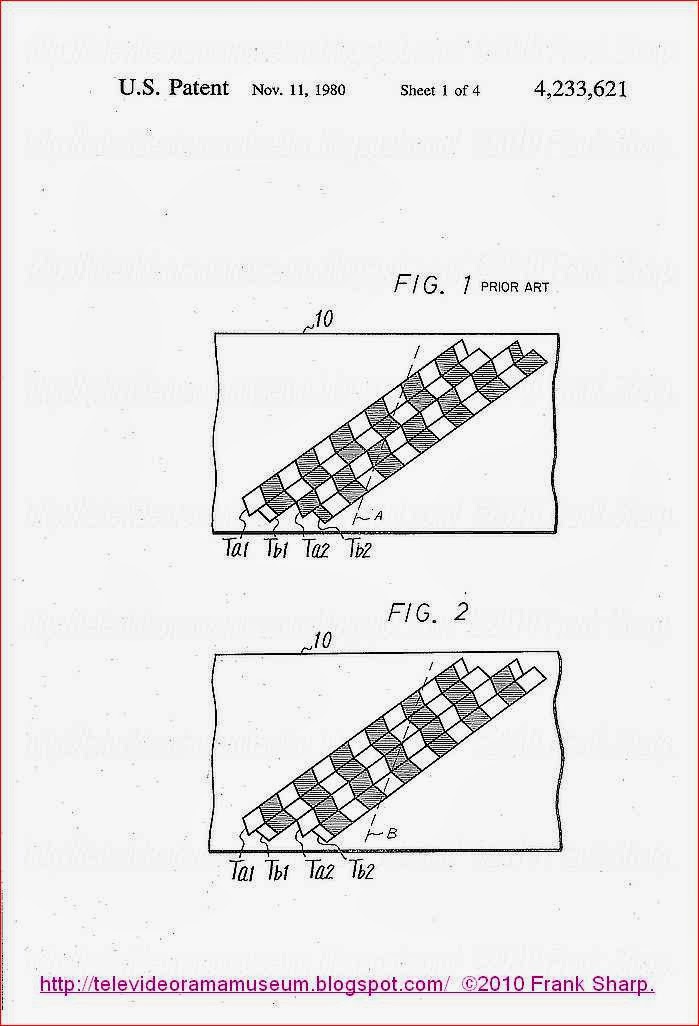 Turning
now to the drawings, FIG. 1 has been described hereinabove. It is
recalled that this figure represents the parallel tracks which are
recorded on a record medium 10, such as a magnetic tape, each track
containing a field interval, and two adjacent tracks comprising a frame
interval. Thus, tracks Ta1 and Tb1 constitute the first and second fields of a first frame; and tracks Ta2 and Tb2
constitute the first and second fields in the next adjacent frame. In
accordance with standard recording techniques, the starting edge of the
first field in the second frame, that is, track Ta2, is displaced from the starting edge of the second field in the preceding frame, that is, track Tb1,
by a distance corresponding to 1.5 horizontal line intervals (1.5H).
However, the adjacent tracks which constitute a single frame are
displaced from each other by 0.5H. Thus, tracks Ta1 and Tb1 are displaced from each other by 0.5H, as are tracks Ta2 and Tb2.
The cross-hatched areas in FIG. 1 represent those line intervals in
which the red color difference signals are recorded, and the unhatched
areas represent those line intervals in which the blue color difference
signals are recorded. As mentioned above, during a slow-motion or
still-motion mode of reproduction, the reproducing transducer, or
playback head, scans across the respective tracks along scanning trace
A. It is seen that when the playback head follows scanning trace A, it
traverses two successive line intervals containing information signals
relating to the same color. Specifically, as the head traverses one
track in which the first field of a frame interval is recorded and then
traverses the next adjacent track in which the second field interval of
the preceding frame is recorded, information signals relating to the
same color are reproduced in sequential line intervals. This disrupts
the normal alternate color information which is reproduced from
sequential lines in a SECAM color video signal. Thus, when the tracks
shown in FIG. 1 are scanned for slow-motion or still-motion
reproduction, the color difference signals which are reproduced appear
as (B-Y), (R-Y), (R-Y), (B-Y), (B-Y), and so on, rather than the proper
sequence of (B-Y), (R-Y), (B-Y), (R-Y), and so on.
Turning
now to the drawings, FIG. 1 has been described hereinabove. It is
recalled that this figure represents the parallel tracks which are
recorded on a record medium 10, such as a magnetic tape, each track
containing a field interval, and two adjacent tracks comprising a frame
interval. Thus, tracks Ta1 and Tb1 constitute the first and second fields of a first frame; and tracks Ta2 and Tb2
constitute the first and second fields in the next adjacent frame. In
accordance with standard recording techniques, the starting edge of the
first field in the second frame, that is, track Ta2, is displaced from the starting edge of the second field in the preceding frame, that is, track Tb1,
by a distance corresponding to 1.5 horizontal line intervals (1.5H).
However, the adjacent tracks which constitute a single frame are
displaced from each other by 0.5H. Thus, tracks Ta1 and Tb1 are displaced from each other by 0.5H, as are tracks Ta2 and Tb2.
The cross-hatched areas in FIG. 1 represent those line intervals in
which the red color difference signals are recorded, and the unhatched
areas represent those line intervals in which the blue color difference
signals are recorded. As mentioned above, during a slow-motion or
still-motion mode of reproduction, the reproducing transducer, or
playback head, scans across the respective tracks along scanning trace
A. It is seen that when the playback head follows scanning trace A, it
traverses two successive line intervals containing information signals
relating to the same color. Specifically, as the head traverses one
track in which the first field of a frame interval is recorded and then
traverses the next adjacent track in which the second field interval of
the preceding frame is recorded, information signals relating to the
same color are reproduced in sequential line intervals. This disrupts
the normal alternate color information which is reproduced from
sequential lines in a SECAM color video signal. Thus, when the tracks
shown in FIG. 1 are scanned for slow-motion or still-motion
reproduction, the color difference signals which are reproduced appear
as (B-Y), (R-Y), (R-Y), (B-Y), (B-Y), and so on, rather than the proper
sequence of (B-Y), (R-Y), (B-Y), (R-Y), and so on.
The purpose of the present invention is to shift, or displace, the relative positions of the line intervals which are included in alternate frames, such as the even frames, recorded in parallel tracks Ta and Tb. More particularly, by this invention, the line intervals which are recorded in tracks Ta2 and Tb2 are shifted, relative to the line intervals recorded in tracks Ta1 and Tb1, such that all of the line intervals are in coloralignment, as shown in FIG. 2. a1 and the last line interval recorded in track Tb1 contain color information relating to the same color, the first line interval recorded in track Ta2 and the last line interval recorded in track Tb2 likewise include color information signals relating to that very same color. As will be explained below, this format is attained by delaying the chrominance component of the SECAM color video signal in alternate frame intervals by one horizontal line interval. With this delay, the first line interval which is recorded in track Ta2, the track in which the first field of the delayed frame is recorded, is the same line interval as was recorded as the last line interval in immediately preceding track Tb1. Since only alternate frame intervals are delayed, the first and last line intervals in each track for all of the recorded frames contain color information signals relating to the same color, resulting in color-alignment.
 Thus, while the first line interval recorded in track T
When the recorded signals on record medium 10 are reproduced in a slow-motion or still-motion mode, the trace of the playback heads across the surface of the record medium appears as shown by the broken line B. Since the recorded tracks are in color-alignment, the playback head scans alternating color information signals as it proceeds across trace B. Thus, and as shown, in the slow-motion and still-motion modes, the color information signals which are reproduced appears as (B-Y) (R-Y) (B-Y) (R-Y), and so on. Consequently, by reason of this color-alignment which is achieved by the present invention, the proper line-sequence of alternating color information signals are reproduced even during slow-motion and still-motion operation. A SECAM television monitor responds properly to this reproduced color information; and the video picture which is displayed on this monitor is substantially free of color noise. Moreover, the color killer operation will not be carried out erroneously.
Turning now to FIG. 3,
 there is illustrated
apparatus including a recording section and a reproducing section, in
accordnce with one embodiment of the present invention. To facilitate a
ready understanding of this invention, it is assumed that the record
medium upon which the signals are recorded in successive parallel tracks
is a magnetic tape. Furthermore, it is assumed that the signals are
color video signals and, specifically, they are SECAM color video
signals wherein color information signals relating to different colors
are present alternately in sequential line intervals. Of course, and as
will be apparent, other periodic information signals can be recorded on
the magnetic tape, such periodic information signals being constituted
by a predetermined number of sub-intervals included in a field interval,
and a predetermined number of field intervals included in a frame
interval.
there is illustrated
apparatus including a recording section and a reproducing section, in
accordnce with one embodiment of the present invention. To facilitate a
ready understanding of this invention, it is assumed that the record
medium upon which the signals are recorded in successive parallel tracks
is a magnetic tape. Furthermore, it is assumed that the signals are
color video signals and, specifically, they are SECAM color video
signals wherein color information signals relating to different colors
are present alternately in sequential line intervals. Of course, and as
will be apparent, other periodic information signals can be recorded on
the magnetic tape, such periodic information signals being constituted
by a predetermined number of sub-intervals included in a field interval,
and a predetermined number of field intervals included in a frame
interval.
The video signals are recorded on magnetic tape 10 by a pair of rotary transducers, or record heads 12a and 12b. These record heads are rotatably driven by a drive shaft mechanically coupled to a drive motor 13. Tape 10 is deployed about at least 180° of the periphery of a guide drum and is longitudinally transported by conventional tape-drive apparatus, such as the combination of a capstan and a pinch roller. Motor 13, which is driven by a servo-control circuit (not shown), rotates record heads 12a and 12b at the frame repetition rate of the SECAM color video signal, e.g. 25 rotations per second. As each frame includes two field intervals, each of record heads 12a and 12b functions to record a field in a respective track across tape 10.
The recording section of the illustrated apparatus includes a luminance channel, for separating and processing the luminance component included in the color video signal, and a chrominance channel for separating and processing the chrominance component included in the video signal. The luminance channel is comprised of a low pass filter 15, a gain-controlled amplifier 16, a clamp circuit 17, a pre-emphasis circuit 18, a dark-and-white clipper 19, and a frequency modulator 20. The luminance channel is connected to an input terminal 14 for receiving the composite color video signal. Low pass filter 15 is connected to this input terminal for separating the luminance component, which is
contained in a relatively lower frequency band, from the chrominance
component. The output of low pass filter 15 is connected to
gain-controlled amplifier 16, which comprise an automatic gain control
(AGC) amplifier. AGC amplifier 16 is connected to clamp circuit 17, the
latter serving to compensate for level changes in the luminance
component by clamping the DC level thereof to a reference level, such as
the pedestal level.
The output of clamp circuit 17 is supplied through pre-emphasis circuit 18, which may be a conventional pre-emphasis circuit, to dark-and-white clipper 19. This clipper serves to prevent the dark and white levels of the luminance component from exceeding predetermined values. The luminance component provided at the output of clipper 19, which is a properly compensated and prepared luminance component, is supplied to frequency modulator 20 wherein the luminance component frequency-modulates a carrier of relatively higher frequency, resulting in a frequency-modulated (FM) luminance component. This higher frequency FM luminance component is supplied through a high pass filter 21 to a combining circuit 22, shown herein as a summing circuit. This combining circuit is adapted to combine the chrominance component processed by the chrominance channel with the FM luminance component, and then to supply the combined signal through a recording amplifier 30 and the record contact R of a change-over switch SW1 to heads 12a and 12b.
Preferably, in order to exploit the aforementioned phenomenon of azimuth loss for eliminating cross-talk interference due to the higher frequency luminance component which may be picked up from an adjacent record track during the reproducing operation, heads 12a and 12b are provided with air gaps of different azimuth angles. Hence, if the higher frequency FM luminance component which is recorded in a record track by head 12a is, subsequently, reproduced by head 12b, this reproduced FM luminance component will be substantially attenuated because of azimuth loss.
The chrominance channel included in the recording section of the illustrated apparatus includes a high pass filter 23, a reverse bell filter 24, an automatic chrominance control (ACC) circuit 25, a selective delay circuit comprised of a delay circuit 26 and a change-over switch 27, and a frequency converter 28. High pass filter 23 is connected to input terminal 14 to receive the composite color video signal and to separate the chrominance component, which is included in a relatively higher frequency band, from the luminance component. The output of this high pass filter is connected to reverse bell filter 24,
the latter having a frequency characteristic which resembles the inverse
of a bell-shaped curve. Hence, reverse-bell filter 24 serves, in part,
to provide some frequency compensation to the filtered chrominance
component, resulting in a chrominance component exhibiting a relatively
flat frequency characteristic. The output of the reverse bell filter is
supplied through ACC circuit 25 to the selective delay circuit. The ACC
circuit is adapted to control the level of the filtered chrominance
component so as to eliminate undesired amplitude fluctuations therein.
As an example, ACC circuit 33 may include a gate circuit operative to
transmit a discriminating signal which is present during the back porch
portion of each horizontal synchronizing signal, and which is
constituted by an unmodulated chrominance subcarrier which is equal to
the subcarrier that is frequency-modulated in the remainder of the line
interval. The amplitude of this transmitted discriminating signal is
detected and used to adjust the amplitude of the chrominance component
accordingly. As an alternative, since the chrominance component is
comprised of frequency-modulated blue and red subcarriers, and since
color information is not represented by amplitude fluctuations, such
amplitude fluctuations can be removed by ACC circuit 33 if this ACC
circuit is a limiter.
The output of ACC circuit 25 is supplied through the selective delay circuit to frequency converter 28. In this selective delay circuit, delay circuit 26 is adapted to impart a delay equal to one horizontal line interval (referred to herein as a 1H delay) to the signals which are supplied thereto. As shown, the output of ACC circuit 25 is connected to the input of 1H delay circuit 26. Change-over switch 27, sometimes referred to herein as a switching circuit, is provided with fixed input contacts a and b, and a movable output contact c selectively controlled so as to engage either of its input contacts. A switch control circuit, described below, supplies a switch control signal to the control input of change-over switch 27, this switch control signal being determinative of the particular input contact to which the output contact is connected. As shown, input contact a is connected directly to the output of ACC circuit 25 so as to receive an undelayed signal therefrom; and input contact b is connected to the output of 1H delay circuit 26 so as to receive a delayed signal. Output contact c is connected to frequency converter 28.
The frequency converter is adapted to frequency-convert the chrominance components supplied thereto to a frequency band which is substantially below the frequency band of the FM luminance component produced by frequency modulator 20. In this regard, frequency divider 28 may include a modulating or heterodyning circuit which is supplied with the chrominance component from change-over switch 27 and a frequency-converting signal from a suitable source. These respective signals are heterodyned, and preferably, the lower sideband, or difference frequency, is derived from the output of the frequency converter. Such frequency converters are known to the prior art. In another embodiment, frequency converter 28 may be of the type described in copending application Ser. No. 960,839, filed Nov. 15, 1978. In either embodiment, the output of frequency converter 28 is supplied through a summing circuit 29 to combining circuit 22 whereat the frequency-converted chrominance component and FM luminance component are combined into a composite signal. This composite signal is supplied through recording amplifier 30 and through change-over switch SW1 to record heads 12a and 12b.
The switch control circuit which determines the operating condition, or state, of change-over switch 27 is comprised of a flip-flop circuit 47, a frequency divider 48 and a change-over switch SW2. Flip-flop
circuit 47 is of the so-called RS type including a set input S and a
reset input R. The state of flip-flop circuit 47 is determined by the
signals which are supplied to the set and reset inputs thereof,
respectively. More particularly, this flip-flop circuit is set in
response to a binary "1" applied to its S input and is reset in response
to a binary "1" applied to its R input. Flip-flop circuit 47 is
included in a sensing circuit which is adapted to sense the rotary
positions of heads 12a and 12b. In this regard, the drive shaft which
extends from motor 13 and is used to rotatably drive heads 12a and 12b
is provided with magnetic elements spaced thereon. These magnetic
elements rotate with the drive shaft and are detected by fixedly
disposed magnetic detectors 45a and 45b. One magnetic element is
particularly disposed so as to be detected by magnetic detector 45a when
head 12a rotates into position so as to commence scanning a record
track across tape 10. The other magnetic element is particularly
disposed on the drive shaft so as to be detected by magnetic detector
45b when head 12b rotates into position to commence scanning a record
track across the tape. Magnetic detectors 45a and 45b are adapted to
produce detecting pulses when the respective magnetic elements are
detected thereby, these detecting pulses being supplied to the S and R
inputs of flip-flop circuit 47 by amplifiers 46a and 46b, respectively.
The output of flip-flop circuit 47, which may comprise a rectangular pulse signal representing the state of the flip-flop circuit, is coupled through frequency divider 48 to the control input of change-over switch 47. Frequency divider 48 may comprise a conventional frequency-dividing circuit, such as a triggerable flip-flop circuit, adapted to divide the frequency of the rectangular pulse signal supplied thereto from flip-flop circuit 47 by a factor of 2. The output of frequency divider 48 also is coupled to the record contact R of change-over switch SW2 to a monostable multivibrator 49, the output of which being coupled to another monostable multivibrator 15.
Monostable multivibrators 49 and 50 are adapted to respond to the output of frequency divider 48 for producing a gate pulse Pg of predetermined duration at a predetermined time. This gate pulse is used during the recording operation to control the insertion of a discriminating signal into the frequency-converted chrominance component. As will be described below, the presence of this discriminating signal is used as an indication of the particular frames of video signals which are shifted in the recording thereof, as shown in
FIG. 2. The circuit for producing and inserting this discriminating
signal is comprised of a reference oscillator 51, a switching circuit
52, such as a gating circuit, and change-over switches SW3 and SW4.
Reference oscillator 51 is adapted to produce an oscillating signal of
substantially constant frequency. This oscillating signal is used as the
discriminating signal and is supplied to switching circuit 52 via the
record contact R of change-over switch SW3. A control signal, that is, the gating signal Pg,
is applied to switching circuit 52 by monostable multivibrator 50. The
output of this switching circuit is coupled via the record contact R of
change-over switch SW4 to summing circuit 29 whereat the
discriminating signal is combined with, or inserted into, the
frequency-converted chrominance component. The output of summing circuit
29 is connected to combining circuit 22.
The manner in which the recording section illustrated in FIG. 3 operates now will be described with reference to the waveform diagrams of FIGS. 4A-4D and 5A-5E. The luminance component is processed to an FM luminance component by a luminance channel in a manner which is known to those of ordinary skill in the art. Hence, in the interest of simplification, further description of this known operation is not provided herein.
As motor 13 rotatably drives heads 12a and 12b, magnetic detectors 45a and 45b produce detecting pulses when the respective magnetic elements which are disposed on the drive shaft rotate therepast. It is appreciated that each magnetic detector produces detecting pulses at a rate corresponding to the frame rate, that is, the rate at which each head is rotated. Thus, flip-flop circuit 47 is set when head 12a scans tape 10 to record a field of video signals, and this flip-flop circuit is reset when head 12b scans the tape to record the next field of video signals. This operation of flip-flop circuit 47 results in the rectangular pulse signal P25 produced thereby, as shown in FIG. 4A. Thus, the flip-flop circuit is set for the duration of field interval ta1 in the first frame, then is reset for the duration of field interval tb1 in the first frame, then is set for the duration of field interval ta2 in the second frame, then is reset for the duration of field interval tb2 in the second frame, and so on. The frequency of the rectangular pulse signal P25 is divided by frequency divider 48, resulting in the divided rectangular pulse signal Pf, shown in FIG. 4. It is appreciated that this divided pulse signal is at its relatively higher binary "1" level for the duration of one frame and then is at its relatively lower binary "0" level for the duration of the immediately following frame. For convenience in describing the operation of the illustrated apparatus, it is assumed that the frequency-divided pulse signal Pf, which is seen to be the switch control signal, is a binary "1" for odd frames and is a binary "0" for even frames. Of course, if desired, this relationship can be reversed wherein the switch control signal is a binary "1" for even frames and is a binary "0" for odd frames.
Switching circuit 27 is operated such that output contact c engages input contact a when the switch control signal applied thereto is a binary "1". When the state of the switch control signal reverses to a binary "0", switching circuit
27 is operated so as to connect output contact c to input contact b.
Thus, for each odd frame, the undelayed frame of the chrominance
component provided at the output of ACC circuit 25 is coupled via
switching circuit 27 to frequency converter 28. However, for each even
frame, the delayed chrominance component provided at the output of 1H
delay circuit 26 is supplied to frequency converter 28 by switching
circuit 27. This means that each even frame interval is delayed by one
horizontal line interval. The frequency converter supplies the
frequency-converted chrominance component, having alternating delayed
and undelayed frames, to combining circuit 22 via summing circuit 29,
for combining with the FM luminance component, and for recording in
successive parallel tracks on tape 10 by heads 12a and 12b. It is
appreciated that, by delaying alternate frames of the chrominance
component by one horizontal line interval, successive frames are
recorded in the format shown in FIG. 2, whereby all of the record tracks
are disposed in color-alignment.
Monostable multivibrator 49 is responsive to the positive transition in switch control signal Pf (FIG. 4B) to produce a timing pulse of predetermined duration τ1. At the negative transition of this timing pulse, monostable multivibrator 50 is triggered to produce gating pulse Pg having the predetermined duration τ2, as shown in FIG. 4C. Hence, this gating pulse is provided at a repetition frequency equal to one-half the frame repetition rate. Stated otherwise, gating pulse Pg is provided at a predetermined location in each odd frame. This gating pulse is supplied to gate circuit 52 for opening this gate so as to couple the discriminating signal produced by oscillator 51 through change-over switch SW4. FIG. 4D represents this discriminating signal Sf which is applied to summing circuit 29 whereat it is inserted into the frequency-converted chrominance component Ss. The combined frequency-converted chrominance component and inserted discriminating signal (Ss +Sf) is combined with the FM luminance component in combining circuit 22, the resultant composite video signal being recorded in successive tracks by heads 12a and 12b. It is recognized that the discriminating signal Sf is inserted only for predetermined durations at predetermined locations of the frequency-converted chrominance component Ss.
The location of the chrominance component in which discriminating signal Sf is inserted now will be described with reference to the waveform diagrams of FIGS.
 5A-5E. Let it be assumed that a portion of the
incoming video signal, including the vertical synchronizing interval,
appears as shown in FIG. 5A, wherein each horizontal line interval is
defined by the periodic horizontal synchronizing pulses HD, and wherein
the video information signals, including both the luminance and
chrominance components, are represented as amplitude-varying signals
between successive horizontal synchronizing pulses. The vertical
blanking interval is represented as VBLK, and the vertical synchronizing
pulse is represented as VD. As is conventional, a plurality of
equalizing pulses are provided before and after the vertical
synchronizing pulse interval, and a plurality of vertical synchronizing
pulses are present during the vertical synchronizing pulse interval.
Furthermore, and in accordance with the SECAM convention, line
discriminating signals are provided in successive line intervals
following the equalizing pulses in the vertical blanking interval VBLK.
These line discriminating signals are formed of unmodulated blue and red
subcarriers which are present in alternate line intervals. Thus, if the
blue line discriminating signal is represented as DB and the red line
discriminating signal is represented as DR, then the line discriminating
signals are present in the sequence DB, DR, DB, DR, etc., for a given
number of line intervals during the vertical blanking interval for
odd-numbered frames; and these line discriminating signals are present
in the sequence DR, DB, DR, DB, etc. for the given (e.g. 9) number of
line intervals for the even-numbered frames. The purpose of these line
discriminating signals is to condition switching circuitry included in a
conventional SECAM television receiver to supply the chrominance
components which are received during successive line intervals to the
proper demodulators.
5A-5E. Let it be assumed that a portion of the
incoming video signal, including the vertical synchronizing interval,
appears as shown in FIG. 5A, wherein each horizontal line interval is
defined by the periodic horizontal synchronizing pulses HD, and wherein
the video information signals, including both the luminance and
chrominance components, are represented as amplitude-varying signals
between successive horizontal synchronizing pulses. The vertical
blanking interval is represented as VBLK, and the vertical synchronizing
pulse is represented as VD. As is conventional, a plurality of
equalizing pulses are provided before and after the vertical
synchronizing pulse interval, and a plurality of vertical synchronizing
pulses are present during the vertical synchronizing pulse interval.
Furthermore, and in accordance with the SECAM convention, line
discriminating signals are provided in successive line intervals
following the equalizing pulses in the vertical blanking interval VBLK.
These line discriminating signals are formed of unmodulated blue and red
subcarriers which are present in alternate line intervals. Thus, if the
blue line discriminating signal is represented as DB and the red line
discriminating signal is represented as DR, then the line discriminating
signals are present in the sequence DB, DR, DB, DR, etc., for a given
number of line intervals during the vertical blanking interval for
odd-numbered frames; and these line discriminating signals are present
in the sequence DR, DB, DR, DB, etc. for the given (e.g. 9) number of
line intervals for the even-numbered frames. The purpose of these line
discriminating signals is to condition switching circuitry included in a
conventional SECAM television receiver to supply the chrominance
components which are received during successive line intervals to the
proper demodulators.
The switch control signal Pf, produced by frequency divider 48, and discussed previously with respect to FIG. 4B, is illustrated in FIG. 5B relative to the vertical blanking interval provided at the beginning (or end) of each frame. It is recalled that the generation of this switch control pulse Pf is dependent upon the detection of the magnetic elements provided on the drive shaft for record heads 12a and 12b by magnetic detectors 45a and 45b. Thus, the commencement of switch control pulse Pf is dependent upon the particular positioning of these magnetic elements. g which is produced for a duration τ2 at a delayed time τ1 following the beginning of the switch control signal Pf. FIG. 5D represents the output of gate circuit 52, wherein the discriminating signal Sf is provided during the duration of the gate pulse Pg. These signals have, of course, been described previously with respect to FIGS. 4C and 4D, respectively.
FIG. 5C represents the gate pulse P
FIG. 5E represents the combination of the frequency-converted chrominance component and the inserted discriminating signal (Ss +Sf) which is combined with the FM luminance component in combining circuit 22. The line intervals which precede the inserted discriminating signal Sf are seen to contain the frequency-converted chrominance component, these chrominance components being constituted by alternate blue and red frequency-converted subcarriers which are frequency-modulated with the blue and red difference signals, respectively. Following the inserted discriminating signal Sf are the alternating line discriminating signals DB, DR, DB, DR, etc., as shown. Preferably, the inserted discriminating signal Sf should be present fora
duration which is as long as possible, but does not interfere with or
overlap any of the line discriminating signals DB, DR. Thus, the time
constant of monostable multivibrator 50 should be selected accordingly.
In a numerical example, the average frequency of the frequency-converted blue and red subcarriers is about 680 KHz. The frequency of the oscillating signal produced by reference oscillator 51 is about twice this average frequency, or about 1.3 MHz. Hence, the frequency of the discriminating signal is at the upper limit, yet is within the frequency band of the frequency-converted chrominance component Ss and, therefore, is below the frequency band of the FM luminance component.
In view of the foregoing discussion of the illustrated apparatus, it is appreciated that record head 12a is adapted to record the first field, for example, in each frame and record head 12b is adapted to record the second field in each frame. Thus, field ta1 is recorded by head 12a in track Ta1, and field tb1 is recorded by head 12b in track Tb1. Then, in the next frame, field ta2 is recorded by head 12a in track Ta2, and field tb2 is recorded in track Tb2 by head 12b. Alternate ones of the frames are delayed by one horizontal line interval. In the embodiment discussed herein, the chrominance component in the even-numbered frames, which are present when switch control signal Pf is a binary "0", are delayed by one horizontal line interval, are frequency-converted and then are recorded. The chrominance component included in the odd-numbered frames, that is, those frames which are present when switch control signal Pf is a binary "1", are frequency-converted and then recorded in undelayed fashion. Although FIG. 4D represents that the discriminating signal Sf, which will be described below as being used as a frame discriminating signal, is inserted into the vertical blanking interval of the first field of the odd-numbered frames, that is, the first field of those frames which are not delayed, it will be apparent that, if desired, this
discriminating signal Sf can be inserted into the vertical blanking interval of the first field in each of the even-numbered frames.
As shown in FIG. 3, heads 12a and 12b are angularly displaced from each other by an amount equal to 180°-α. If the angular separation of these heads is equal to 180°, then the beginning of the tracks Tb recorded by head 12b will be displaced, or shifted, from the beginning of the tracks Ta recorded by head 12a by an amount equal to one horizontal line interval in the direction of the track. However, in the SECAM convention, each field is comprised of 312.5 line intervals. Thus, if the horizontal synchronizing intervals in adjacent tracks are to be aligned, the track containing the second field in a frame should be shifted from the track containing the first field in that frame by an amount equal to 0.5 line intervals. This shift is attained by displacing head 12b by the angular amount α from a 180° displacement relative to head 12a. That is, if the heads are angularly displaced from each other by an amount equal to 180°-α, then, in the recording of each frame, track Tb will be shifted by an amount equal to 0.5 line intervals relative to track Ta. Furthermore, and as is preferred for the recording of successive tracks in H-alignment (i.e., with their horizontal synchronizing intervals in alignment), the first track in which the next following frame is recorded is shifted from the preceding track in which the preceding frame is recorded by an amount equal to 1.5 line intervals.
 The
apparatus illustrated in FIG. 3 also includes a reproducing section
which is comprised of a luminance channel for separating and processing
the reproduced luminance component, and a chrominance channel which is
provided to separate and process the reproduced chrominance component.
The luminance channel is comprised of a high pass filter 32, a limiter
34, a frequency demodulator 35 and a de-emphasis circuit 36. High pass
filter 32 is connected via a playback amplifier 31 and playback contact P
of change-over switch SW1 to heads 12a and 12b. The high
pass filter is adapted to pass the higher frequency band of the FM
luminance component and to attenuate the lower frequency band of the
frequency-converted chrominance component. Thus, of the reproduced video
signals, only the luminance component is supplied through the high pass
filter. Limiter 34 is connected to the output of high pass filter 32
and serves to eliminate amplitude fluctuations of the FM luminance
component. The output of the limiter is coupled to frequency demodulator
35 which serves to demodulate the FM luminance component back to its
original frequency band, and to produce an amplitude-varying luminance
signal. The output of frequency demodulator 35 is coupled through
de-emphasis circuit 36 to a combining circuit 37. De-emphasis circuit 36
is the complement of pre-emphasis circuit 18 and functions in
conventional manner. Thus, combining circuit 37, which may comprise a
summing circuit, is provided with a substantially original version of
the luminance component.
The
apparatus illustrated in FIG. 3 also includes a reproducing section
which is comprised of a luminance channel for separating and processing
the reproduced luminance component, and a chrominance channel which is
provided to separate and process the reproduced chrominance component.
The luminance channel is comprised of a high pass filter 32, a limiter
34, a frequency demodulator 35 and a de-emphasis circuit 36. High pass
filter 32 is connected via a playback amplifier 31 and playback contact P
of change-over switch SW1 to heads 12a and 12b. The high
pass filter is adapted to pass the higher frequency band of the FM
luminance component and to attenuate the lower frequency band of the
frequency-converted chrominance component. Thus, of the reproduced video
signals, only the luminance component is supplied through the high pass
filter. Limiter 34 is connected to the output of high pass filter 32
and serves to eliminate amplitude fluctuations of the FM luminance
component. The output of the limiter is coupled to frequency demodulator
35 which serves to demodulate the FM luminance component back to its
original frequency band, and to produce an amplitude-varying luminance
signal. The output of frequency demodulator 35 is coupled through
de-emphasis circuit 36 to a combining circuit 37. De-emphasis circuit 36
is the complement of pre-emphasis circuit 18 and functions in
conventional manner. Thus, combining circuit 37, which may comprise a
summing circuit, is provided with a substantially original version of
the luminance component.
The chrominance channel is comprised of a low pass filter 33, an ACC circuit 38, a frequency re-converter 39, a selective delay circuit formed of a delay circuit 40 and a switching circuit 41, and a bell filter 43. Low pass filter 33 is connected to heads 12a and 12b via the playback contact P of change-over switch SW1 and playback amplifier 31. The low pass filter is adapted to pass the relatively lower frequency band containing the frequency-converted chrominance component and the inserted discriminating signal, while attenuating the higher frequency band of the FM luminance component. The output of low pass filter 33 is coupled to ACC circuit 38 which is similar to ACC circuit 25 and serves to eliminate undesired amplitude fluctuations in the reproduced frequency-converted chrominance component. The output of ACC circuit 38 is connected to frequency re-converter 39 which is adapted to re-convert the chrominance component substantially back to its original frequency band. Hence, frequency re-converter 39 may include a modulating or heterodyning circuit which is supplied with a re-converting signal for heterodyning both the reproduced frequency-converted chrominance component and the re-converting signal. The lower side band of the heterodyned signals is selected, this lower side band constituting the frequency re-converted chrominance component. As is recognized, frequency re-converter 39 should be compatible with frequency converter 28. One type of frequency re-converter may be as described in copending application Ser. No. 960,839.
The output of frequency re-converter 39 is coupled to
the selective delay circuit. More specifically, the selective delay
circuit includes a 1H delay circuit 40 which is adapted to impart a time
delay equal to one horizontal line interval to the frequency
re-converted chrominance component supplied thereto. The selective delay
circuit also includes switching circuit 41 which is provided with a
fixed input contact a connected directly to the output of frequency
re-converter 39 and a fixed input contact b which is connected to the
output of 1H delay circuit 40. Switching circuit 41 is schematically
illustrated as including a movable output contact c which is selectively
engageable with input contacts a and b, depending upon the state of a
switch control signal supplied to a control input thereof. The output of
switching circuit 41, that is, the output derived at output contact c,
is connected to bell filter 43 which is provided with a frequency
characteristic that is complementary to the frequency characteristic of
reverse bell filter 24. Thus, bell filter 43 is adapted to restore the
frequency re-converted chrominance component back to its original
frequency characteristic.
The switch control signal which is supplied to switching circuit 41 is the phase-inverted version of the switch control signal Pf, described above, and used to control switching circuit 27 in the recording section. Accordingly, switch control signal Pf,
produced by frequency divider 48, is supplied to the control input of
switching circuit 41 via an inverter 42. It is appreciated that, for the
proper operation of the reproducing section, the switch control signal
which is produced during the reproducing operation must be synchronized
with the switch control signal which is produced during the recording
operation. This is provided by making sure that the output of frequency
divider 48 is at its proper level at the time that the discriminating
signal Sf is reproduced. The circuit for controlling
frequency divider 48 accordingly is comprised of gating circuit 52, a
tuned amplifier 53, a detector 54 and a wave shaper 55. Gating circuit
52 has been described hereinabove with respect to the recording section
of the illustrated apparatus. During the reproducing operation, the
input of this gating circuit is connected to low pass filter 33 via the
playback contact P of change-over switch SW 3, and the output of this gating circuit is connected to tuned amplifier 53 via the playback contact P of change-over switch SW4.
Tuned amplifier 53 is adapted to amplify a signal having a frequency
equal to the frequency to which the amplifier is tuned. In the
illustrated apparatus, tuned amplifier 53 is adapted to amplify the
discriminating signal Sf whose frequency corresponds to the
tuned frequency of the tuned amplifier. The output of tuned amplifier 53
is coupled to detector 54 which, in turn, is coupled to wave shaper 55.
The detector serves to detect the amplified discriminating signal Sf
supplied thereto by tuned amplifier 53 and to produce an output pulse
when this discriminating signal is so detected. Wave shaper 55 is
adapted to shape the output pulse produced by detector 54 to a desired
pulse waveform. The output of wave shaper 55 is coupled to frequency
divider 48. If the frequency divider is a triggerable flip-flop circuit,
as suggested above, then the shaped pulse provided by wave shaper 55 is
adapted to set the triggerable flip-flop circuit to a predetermined
state, such as to "force-set" the flip-flop circuit. Hence, if the
output Pf of frequency divider 48 is a binary "0" at the time that the reproduced discriminating signal Sf is detected, frequency divider 48 will be "forced-set" so as to change the state of the output Pf to a binary "1". Conversely, if the output Pf
is a binary "1" when the reproduced discriminating signal is detected,
the shaped pulse produced by wave shaper 55 will not affect this output.
Gating circuit 52 is supplied with the gate pulse Pg produced by monostable multivibrator 50, described above. However, during the reproducing operation, change-over switch SW2 does not coupled the output of frequency divider 48 to monostable multivibrator 49. Rather, the playback contact P of this change-over switch couples the rectangular pulse signal output P25 of flip-flop circuit 47 to monostable multivibrator 49.
In describing the operation of the reproducing section of the illustrated apparatus, it is assumed that heads 12a and 12b which were used to record the video signals in successive tracks, as shown in FIG. 2, also are used to reproduce those recorded signals. It is further assumed that motor 13, magnetic detectors 45a and 45b and flip-flop circuit 47 are used both during the recording operation and during the reproducing operation. Of course, if separate VTR's are used for recording and reproduction, then separate heads will be used for these purposes. Nevertheless, the operation of motor 13, magnetic detectors 45a and 45b
and flip-flop circuit 47 in the reproducing VTR will be the same as in
the recording VTR, and as described hereinabove with respect to the
recording section. It is also recognized that if separate recording and
reproducing VTR's are employed, the azimuth angles of the air gaps in
heads 12a and 12b for reproduction will be the same as the azimuth
angles which are used for recording.
In a reproducing operation, all of change-over switches SW1 -SW4 are changed over to their playback P contacts. As motor 13 rotatably drives heads 12a and 12b, the recorded video signals in tracks Ta and Tb, as shown in FIG. 2, are reproduced and supplied via the playback contact P of change-over switch SW1 to playback amplifier 31. High pass filter 32 separates the FM luminance component from the reproduced video signals, and the luminance channel functions in a manner known to those of ordinary skill in the art to reproduce the original luminance component. This luminance component is supplied to combining circuit 37.
Low pass filter 33, included in the chrominance channel, separates the chrominance component and inserted discriminating signal to supply these combined signals (Ss +Sf) through ACC circuit 38 to frequency re-converter 39. ACC circuit 38 removes undesired amplitude fluctuations from the reproduced chrominance component Ss ; and frequency re-converter 39 operates to re-convert the reproduced chrominance component substantially back to its original frequency band. The re-converted chrominance component includes alternating delayed and undelayed frames, the delayed frame exhibiting a 1H delay with respect
to the undelayed frame. These alternating frames are supplied directly
to input contact a of switching circuit 41, and through 1H delay circuit
40 to input contact b of the switching circuit.
The manner in which switching circuit 41 is controlled now will be described with reference to FIG. 6. The operation of flip-flop circuit 47 in producing rectangular pulse signal P25 has been described previously with respect to FIG. 4A. This rectangular pulse signal is shown again in FIG. 6A. The frequency of this rectangular pulse signal is divided in frequency divider 48 to produce output Pf, this output being used as the switch control signal for controlling the operation of switching circuit 27 in the recording section. FIG. 4B shows this output, shown again inf of this output. It is appreciated that the phase-inverted version Pf is used as the switch control signal for switching circuit 41 in the reproducing section. It is assumed that switching circuit 41 is substantially similar to switching circuit 27 and operates in an analogous manner. Hence, when switch control signal Pf is at its binary "1" level, switching circuit 41 operates to couple input contact a to output contact c. Conversely, when switch control pulse Pf is at its binary "0" level, the switching circuit operates to couple input contact b to output contact c. As will be described, during reproduction, output Pf is identical to output Pf during recording. That is, output Pf is a binary "1" at each odd frame and is a binary "0" at each even frame. It is recalled that the even frames are subjected to a 1H delay.
FIG. 6B, and FIG. 6C shows the phase-inverted
version P
Since switching circuit 41 is controlled by the phase-inverted switch control pulse Pf, the phase-inverted switch control pulse is a binary "0" when each odd-numbered frame is reproduced and is a binary "0" when each even-numbered frame is reproduced. This, of course, is the opposite of the state of the switch control pulse Pf during the recording operation. As a consequence thereof, when inverted switch control pulse Pf is a binary "0", the odd-numbered undelayed frame is being reproduced. Switching circuit 41 is controlled by this inverted switch control pulse Pf to couple the output of 1H delay circuit 40 to bell filter 43. This means that the reproduced undelayed frame is frequency re-converted and then subjected to a delay equal to one horizontal line interval, that is, equal to the delay imparted to the even-numbered frames during recording, and switching circuit 41 supplies the 1H delayed output of frequency re-converter 39 to bell filter 43. When the even-numbered frames are reproduced from tape 10, inverted switch control pulse Pf is a binary "1" to operate switching circuit 41 whereby input contact a is connected to output contact c. Thus, when the even-numbered frames are reproduced, the output of frequency re-converter 39 is connected directly to bell filter 43 without passing through any delay circuit. Since the even-numbered frames had been delayed by one horizontal line interval during the recording operation, these delayed frames are not further delayed during the reproducing operation.
Thus, it is seen that since those reproduced frames which had not been delayed during the recording operation are delayed by one horizontal line interval, while those reproduced frames which had been delayed during the recording operation are not delayed during the reproducing operation, the relative delay between odd-numbered and even-numbered frames which had been imparted during recording is
compensated, or eliminated, during reproduction. That is, whereas the
even-numbered frames had been delayed during recording, it is the
odd-numbered frames (i.e., the originally undelayed frames) that are
delayed during reproduction.
The reproduced frequency-converted chrominance component and inserted discriminating signal (Ss +Sf), shown in FIG. 5E, are supplied through low pass filter 33 and the playback contact P of change-over switch SW3 to gating circuit 52. The purpose of this gating circuit during the reproducing operation is to search for the inserted discriminating signal Sf. In this regard, the rectangular pulse signal P25 (FIG. 6A) produced by flip-flop circuit 47 and representing the particular track which is reproduced by heads 12a and 12b is supplied through the playback contact P of change-over switch SW2 to monostable multivibrator 49. As in the recording operation, monostable multivibrators 49 and 50 respond to the positive transition in each pulse signal supplied thereto to produce the gating pulse Pg (FIG. 6D) at the output of monostable multivibrator 50. This gating pulse, having the duration τ2, is supplied to gating circuit 52 to operate (i.e., open) the gating circuit during the selected time intervals established by the gating pulse. During the reproducing operation, it is seen that this gating pulse is produced during the vertical blanking interval VBLK in each frame. This differs from the generation of the gating pulse Pg during the recording operation, wherein the gating pulse is produced during the vertical blanking interval during alternate frames (e.g. the odd-numbered frames) only, as shown in FIG. 4C. Thus, during the reproducing operation, gating circuit 52 is opened during the vertical blanking interval in the first field in each frame.
When the discriminating signal Sf is supplied to gating circuit 52, the coincidence of the gating pulse Pg
and the discriminating signal results in passing the reproduced
discriminating signal from the gating circuit to tuned amplifier 53. The
tuned amplifier amplifies this discriminating signal, and the amplified
discriminating signal is detected by detector 54. Wave shaper 55 shapes
the pulse produced by the detector to supply a correction pulse Pc to frequency divider 48, as shown in FIG. 6F. c is produced when output Pf from frequency divider 48 is a binary "1". This corresponds to the gating of the discriminating signal Sf when switch control pulse Pf is a binary "1", as shown in FIGS. 4B and 4D, during the recording operation. In the event that the output Pf of frequency divider 48 during the reproducing operation is a binary "0" at the time that the discriminating signal Sf is reproduced, correction pulse Pc changes the state of output Pf, as shown in FIG. 6G. That is, correction pulse Pc
is used to "force-set" the triggerable flip-flop circuit which may be
provided as frequency divider 48 in the event that this triggerable
flip-flop circuit is in its reset state at the time that the
discriminating signal Sf is reproduced. Consequently, the output Pf
of frequency divider 48 is synchronized during the reproducing
operation so as to be identical to the state thereof during the
recording operation.
From a comparison of FIGS. 6B and 6F, it is seen that the correction pulse P
When the output Pf from frequency divider 48 during the reproducing operation is identical to the output Pf during the recording operation, switching circuit 41 is controlled so as to pass the even-numbered frames of the frequency re-converted chrominance component directly to bell filter 43, and to pass the odd-numbered frames of the frequency re-converted chrominance component through 1 H delay circuit 40 to the bell filter. Thus, during the reproducing operation, only those frames which had not been delayed during the recording operation are subjected to a 1H delay. Hence, at the output of bell filter 43, the successive frames are provided in an equalized time relationship with respect to each other.
It is appreciate that if those frames of the chrominance component which had been delayed during the recording operation also are delayed during the reproducing operation, then such frames, at the output of bell filter 43, will exhibit a time delay of two horizontal line intervals relative to the remaining frames. It is for this reason that, in the reproducing operation, the previously delayed frames are not further delayed, while the previously undelayed frames are subjected to a delay which is equal to the delay imparted in the recording section. Thus, and as one example thereof, during the recording operation, the odd-numbered frames of the chrominance component are not delayed, whereas the even-numbered frames of the chrominance component are delayed. In the reproducing operation, the odd-numbered frames of the chrominance component (which had not been delayed) are delayed, while the even-numbered frames of the chrominance component (which had been delayed) are not delayed.
In the foregoing discussion, the discriminating signal Sf is inserted into the first field of the odd-numbered, undelayed frames
of the chrominance component during the recording operation. As an
alternative thereof, the discriminating signal may be inserted into the
first field of the even-numbered, delayed frames. In either embodiment,
the discriminating signal serves to represent which frames have been
delayed and which frames have not been delayed. Furthermore, although it
has been assumed that, during the recording operation, the
even-numbered frames had been delayed, it is recognized that, if
desired, the odd-numbered frames can be delayed while the even-numbered
frames will not be delayed. In the present invention, alternate frame
intervals of the chrominance component are delayed.
Referring to FIGS. 7A-7E, timing diagrams are illustrated therein which represent the manner in which the present invention operates. FIG. 7A represents the chrominance component Sc1 produced at the output of ACC circuit 25 in the recording section and supplied directly to input contact a of switching circuit 27. FIG. 7B represents the delayed version Sc2 of this chrominance component. It is seen that the delayed chrominance component is delayed by one horizontal line interval. In these figures, the cross-hatched areas represent those line intervals in which the R-Y red color difference signals are present, and the unhatched areas represent those line intervals in which the B-Y blue color difference signals are present. Switching circuit 27 is operated such that undelayed chrominance component Sc1 is supplied to frequency converter 28 during odd-numbered frames, and the delayed chrominance component Sc2
is supplied to the frequency converter during the even-numbered frames.
FIG. 7C represents the alternating delayed and undelayed frames of the
chrominance component Sc3 supplied to the frequency
converter. These frames are frequency-converted and recorded in
successive parallel tracks. It is seen that the first and last line
intervals in each recorded frame contain color information signals
relating to the same color, e.g., the blue color difference signals.
From FIG. 2, it is recognized that this results in color-alignment of
the record tracks.
During reproduction, the alternating delayed and undelayed frames, shown in FIG. 7C, are reproduced. These frames of the frequency-converted chrominance component are re-converted by frequency re-converter 39, whose output is shown in c3. This reproduced chrominance component Sc3 is delayed by 1H delay circuit 40 and supplied as the delayed chrominance component Sc4 to input contact b of switching circuit 41. The undelayed version Sc3 of this reproduced chrominance component is supplied directly to input contact a of the switching circuit. As discussed above, this switching circuit operates so as to supply the output of 1H delay circuit 40 to bell filter 43, that is, delayed circuit Sc4, for those frames which had not been delayed during recording. In the illustrated example, this means that the odd-numbered frames, which had not been delayed during the recording operation, are delayed during reproduction and supplied to bell filter 43. The chrominance component Sc3, which contains delayed even-numbered frames, is supplied by switching circuit 41 to bell filter 43 without further delay. FIG. 7E represents the chrominance component Sc5 supplied to the bell filter by switching circuit 41. It is recognized that, in the reproducing operation, by delaying the previously undelayed frames of chrominance component and by not delaying the previously delayed frames, successive line intervals from one frame to the next will be substantially in the proper line sequential arrangement. Only the first line interval in each odd-numbered frame, which is equal to delayed line interval 624 of the previous frame, may contain an improper color signal. That is, only this first line interval may appear out of proper color sequence during a normal reproducing operation; however, the remaining line intervals in the odd frames are, of course, in proper color sequence. Hence, this has only negligible effect upon the switching circuits included in the conventional SECAM television receiver.
FIG. 7C as the
chrominance component S
While the present invention has been particularly shown and described with reference to a preferred embodiment thereof, it should be readily apparent to those of ordinary skill in the art that various changes and modifications in form and details may be made without departing from the spirit and scope of the invention. Some of these changes and modifications have been discussed and suggested above. In addition to these, it is appreciated that, in the recording section, the selective delay circuit comprised of 1H delay circuit 26 and switching circuit 27 may be connected to the output of frequency converter 28. Similarly, in the reproducing section, the selective delay circuit comprised of 1H delay circuit 40 and switching circuit 41 may be connected to the input of frequency re-converter 39. Also, although the delay imparted to the alternate frames by delay circuits 26 and 40 is equal to one horizontal line interval, it is seen from FIG. 2 that color-alignment will be attained during recording if a delay equal to an odd multiple (2n-1) of horizontal line intervals is imparted by these delay circuits. Furthermore, although the embodiment shown in FIG. 3 is operative to delay the frames of the chrominance component, the incoming SECAM video signal may, alternatively, be delayed.
It is intended that the appended claims be interpreted as including all of the foregoing changes, as well as equivalents thereo.
1. Field of the Invention
This invention relates generally to magnetic recording and/or reproducing apparatus, such as, video tape recording and/or reproducing apparatus (VTR), and more particularly is directed to improvements in a tension control device for such apparatus.
2. Description of the Prior Art
Existing video tape recording and/or reproducing apparatus generally comprise a tape guide drum having one or more rotary magnetic heads associated therewith to record or reproduce video signals on a magnetic tape which is wound on supply and take-up reels with the tape between such reels being wrapped helically about at least a portion of the circumferential surface of the drum and being driven by a cooperating capstan and pinch roller and by suitable rotation of the take-up reel. It will be apparent that, during a recording operation of the foregoing apparatus, each rotary magnetic head will travel obliquely across the tape at an angle to the longitudinal direction of the latter that is determined primarily by the helical path of the tape on the guide drum, the rotational speed
of the rotary magnetic heads and the longitudinal speed at which the
tape is driven by the capstan, whereby to record the video signals in
successive parallel record tracks that are similarly obliquely related
to the tape. When reproducing video signals previously recorded in the
oblique record tracks, either by means of the same or a similar
recording and/or reproducing apparatus, the rotational speed of the
rotary magnetic heads and the speed at which the tape is longitudinally
driven are controlled by suitable servo systems so that each rotary
head, as it commences a scanning movement obliquely across the tape,
will be aligned with a record track. If the magnetic tape is considered
to be dimensionally stable, and assuming that the previously mentioned
factors determining the angle of the oblique record tracks are the same
for the reproducing operation as for the recording operation, then each
rotary magnetic head will scan precisely along an oblique record track
for reproducing the video signals recorded therein. However, the
magnetic tape, being usually formed of a plastic film with a magnetic
coating thereon, is not dimensionally stable, that is, its length may be
varied by changes in temperature, humidity and tension. It will be
apparent that, if the length of the tape changes between the recording
and reproducing operations, then the paths along which the rotary
magnetic heads scan the tape during the reproducing operation will be at
a small angle to the oblique record tracks in which the video signals
are recorded. Therefore, even though each head is aligned with a record
track at the commencement of its scanning movement obliquely across the
tape, the head will deviate from that record track in the course of the
scanning movement and the reproduced video signals will contain guard
band noises which result in a characteristic "snow" or disturbance in
the picture or image displayed by a monitor or other image display
device. It is known to eliminate the above mentioned guard band noises during reproducing operations by suitably varying the tension in the tape so as to compensate for any changes in the longitudinal dimensions thereof that may have occured between the recording and reproducing operations. In existing video tape recording and/or reproducing apparatus, the tape is usually tensioned during recording and reproducing operations by means of a brake which resists rotation of the supply reel, with the braking force applied by such brake being varied in accordance with the tension in a run of the tape between the guide drum and the supply reel.
For example, as disclosed in U.S. Pat. No. 3,833,921, issued Sept. 3, 1974, and having a common assignee herewith, a pivotally mounted tensi
on control arm may be provided with a
pin at its free end pressed against a run of the tape between the guide
drum and the supply reel by means of a spring acting on the arm.
Further, the tension control arm is connected to a band brake which
extends around a brake drum on a rotatable supply reel support member to
resist rotation of the latter, and hence of a supply reel rotatably
coupled therewith. It will be apparent that, in the foregoing
arrngement, the position of the tension control arm is at all times
determined by the force of the spring urging such arm to turn in one
direction and by the tension in the tape run engaged by the pin on the
tension control arm for resisting turning of the latter in that
direction. The band brake is arranged so that a movement of the tension
control arm in one direction in response to a decrease in the detected
tape tension increases the braking force so as to restore the tape
tension to a predetermined value, whereas a movement of the tension
control arm in the opposite direction in response to an increase in the
detected tape tension decreases the braking force for again restoring
the tape tension to the predetermined value. Thus, the described
arrangement tends to maintain a constant tape tension which is
determined by the force of spring acting on the tension control arm. In
order to permit adjustment of the tape tension which is to be
maintained, the existing apparatus connects one end of the spring to the
tension control arm while the opposite end of the spring is connected
to an angularly adjustable anchor arm. Therefore, in theory, when guard
band noises appear in the reproduced video signals by reason of changes
in the longitudinal dimensions of the tape between recording and
reproducing operations, the anchor arm for the spring can be angularly
adjusted to change the spring force, and hence the tape tension, in the
sense required for returning the tape to its longitudinal dimensions
during recording and thereby eliminating the guard band noises. However, it has been found that, in practice, the necessarily fine adjustment of the tape tension cannot be easily achieved by angular adjustment of the anchor arm which is normally locked in a selected position. The foregoing difficulty results from the fact that, when the lock retaining the anchor arm in a selected position is released to permit angular adjustment of the anchor arm, the full force of the associated spring tends to turn the anchor arm in the direction to reduce the spring force. Therefore, the adjustment of the anchor arm has to be effected against the full force of the associated spring which interferes with the precise relocation of the anchor arm to achieve the required precise adjustment of the tape tension.
OBJECTS AND SUMMARY OF THE INVENTION
Accordingly, it is an object of this invention to provide a tension
control device
which avoids the above described difficulties of the prior art, and more
particularly, which facilitates the precise adjustment of the tape
tension in a video tape recording and/or reproducing apparatus, as
aforesaid, for eliminating guard band noises that would otherwise appear
in the reproduced video signals by reason of dimensional changes
occurring in the tape between the recording and reproducing operations. In accordance with an aspect of the invention, a tension control device that includes a movable tension control arm urged against a run of the tape between the supply and take-up reels by means of a tensioning spring so that the positioning of such arm is dependent on the force of the tensioning spring and the tension in the engaged tape run, a brake controllable by the positioning of the tension control arm for resisting rotation of the supply reel so as to maintain a substantially constant tension in the tape run and an anchor member connected with the tensioning spring and being movable for adjusting the force of the tensioning spring and thereby varying the substantially constant tension to be maintained in the tape run; is provided with an arrangement for counterbal
ancing the force of the tensioning spring in respect to the
anchor member, for example, by providing an additional spring which acts
on the anchor member in opposition to the force of the tensioning
spring, so that the anchor member can be adjustably moved without having
to overcome the force of the tensioning spring. It is a further feature of the invention to provide the foregoing tension control device with a manually actuable control element, such as a rotatable knob, and with an irreversible coupling connected between such control element and the anchor member for providing a substantial mechanical advantge in respect to displacement of the control element relative to the resulting movement of the anchor member.
The above, and other objects, features and advantges of this invention, will be apparent from the following detailed description of an illustrative embodiment thereof which is to be read in connection with the accompanying drawings.
BRIEF DESCRIPTION OF THE DRAWINGS
FIG. 1 is a schematic top plan view of a video tape recording and/or reproducing apparatus having a tape loading and unloading device, and which is of a type to which the present invention is applied;
FIG. 2 is an enlarged top plan view of a tension control device according to this invention provided in the apparatus of FIG. 1, with a portion of the chassis of the latter being cut away to show the elements of the tension control device disposed therebelow;
FIG. 3 is a sectional view taken along the line 3-3 on FIG. 2; and
FIG. 4 is a detail perspective view showing a centering arrangement included in the tension control device.
DESCRIPTION OF A PREFERRED EMBODIMENT
A cassette holding device, shown schematically in broken lines and indicated generally by the reference numeral 3, is suitably mounted on a chassis 2 in front of guide drum 1 and is movable between a raised position, in which holding device 3 is adapted to receive a tape cassette 4, and a lowered or operative position, in which the cassette is positioned for a recording or reproducing operation. The tape cassette 4 is shown to include a supply reel 5 and a take-up reel b rotatably contained within a housing 7 and having a magnetic tape T wound thereon. The tape T extending between reels 5 and 6 is guided about guide pins 8a and 8b adjacent reel 5 and about guide pins 9a and 9b adjacent reel 6 so as to normally follow a path including a run, indicated in broken lines at T1, between gu
ide pins 8b and 9b
at which the tape is exposed through an opening 10. The opening 10
extends along the side and adjacent bottom portion of housing 7 which is
directed toward guide drum 1 when cassette 4 is received by holding
device 3. Access to the interior of cassette housing 7 through opening
10 is limited by a partition 11 which extends along the edge of opening
10 in the bottom wall of housing 7 from near guide pin 8b to near guide
pin 9b, and which is spaced inwardly from the run T1 of the tape. Rotatable reel support members 12 and 13 extend upwardly from chassis 2 and are respectively engageable by the hubs 5a and 6a of supply reel 5 and takeup reel 6 when holding device 3 is lowered to its operative position with the cassette 4 received therein. Suitable drive assemblies (not shown) may be provided for driving takeup reel support member 13 in the direction winding the tape T on takeup reel 6 during recording, reproducing and fast-forward operations of the apparatus, and for driving supply reel support member 12 in the direction for rewinding the tape on supply reel 5 during rewinding operation of the apparatus.
The recording and/or reproducing apparatus further includes a capstan 14 which is suitably driven from a drive motor (not shown), a fixed magnetic head assembly 15 for recording and/or reproducing audio and control signals, an erasing head 16 and tape guides 17 and 18, all of which are mounted on chassis 2 at predetermined spaced apart positions, as shown. In order to operate the magnetic recording and/or reproducing apparatus, it is necessary to load the tape from cassette 4 on holding device 3 about at least a portion of the circumferential surface of guide drum 1 for scanning by the rotary magnetic head assembly 1a associated with the guide drum, and further to engage the magnetic tape with capstan 14 for driving by the latter and also with the fixed magnetic heads 15 and 1
6. When it is desired to remove the cassette 4
from the apparatus at the conclusion of a recording or reproducing
operation, it is necessary to unload the tape from about drum 1 and to
return the tape to the cassette 4. In the illustrated apparatus, a device 20 for performing the above described tape loading and unloading functions is shown to generally include a support member 21, preferably in the form of a ring, and which is rotatable about guide drum 1 in a circular or arcuate path that extends under the opening 10 of a cassette 4 positioned by the holding device 3. The support ring 21 may be disposed eccentrically with respect to guide drum 1, to provide a relatively large space therebetween for accommodating capstan 14, heads 15 and 16 and tape guides 17 and 18. Support ring 21 is shown to be rotatably supported by grooved rollers 22 which engage the inner periphery of ring 21 and which are suitably mounted above chassis 2. In order to effect turning of support ring 21 about guide drum 1, the outer periphery of ring 21 is frictionally engaged by a drive roller 23 which is rotatable by a suitable reversible electric motor 24.
Mounted on support ring 21 is a tape engaging assembly 25 which is shown to include a support arm 26 pivoted, at one end, on a pin 27 projecting upwardly from ring 21, a freely rotatable, upstanding pinch roller 28 carried by the opposite or free end portion of arm 26, and a tape engaging member or pin 29 extending upwardly from arm 26 intermediate its ends. The tape engaging assembly 25 is located on support ring 21 so that, when the support ring is turned to its operative position to dispose assembly 25 as shown in full lines on FIG. 1, pinch roller 28 is adjacent capstan 14 for cooperation with the latter in driving the magnetic tape therebetween. In the apparatus as shown, a spring 30 acts on support arm 26 to urge the latter outwardly relative to ring 21 against a stop 31 for providing a small gap between pinch roller 28 and capstan 14, and an additional mechanism, indicated schematically at 32, may be provided to angularly displace support arm 26 in the inward direction for pressing pinch roller 28 against capstan 14. Such additional mechanism 32 may be simply constituted by a solenoid having an armature 32a which is extended in response to the energization of the solenoid during a recording or reproducing operation of the apparatus so as to cause inward movement of arm 26, for example, by direct action of armature 32a on arm 26, as shown.
Tape loading and unloading device 20 is further shown to include a tape shifting assembly 33 which, as hereinafter described in detail, may form part of a tension regulating or control device according to this invention and which is shown on FIG. 1 to include a pin 34 projecting upwardly from one end of a support arm 35 extending swingably over ring 21 from a shaft 36 journalled in chassis 2.
As will be hereinafter described in detail, support arm 35 is spring urged in the counterclockwise direction, that is, in the direction for moving pin 34 from its inoperative position indicated at 34' to its operative position shown in full lines on FIG. 1. A control member or lever 37 for controlling the movements of pin 34 may be pivoted, at one end, on a pin 38 carried by chassis 2 adjacent ring 21 and carries a rotatable cam follower roller 39 which is urged agai
nst the periphery of support ring
21 by a spring 40 connected between an arm 37a of lever 37 and an anchor
40a on the chassis. The free end portion of lever 37 extends adjacent
the pivoted end of support arm 35 and has an upstanding lug 37b
engageable by an extension 35a of arm 35 for limiting the spring-urged
swinging of the latter in the counterclockwise direction. The periphery
of support ring 21 is formed with a recess 41 located to receive cam
follower roller 39 when support ring 21 is in its operative position
(FIG. 1). The periphery of ring 21 is further formed with a cam surface
41a extending from recess 41 in the counterclockwise direction and being
at progressively decreasing radial distances from the center of
rotation of ring 21 in the clockwise direction, that is, in the
direction toward recess 41, so as to be engageable by cam follower
roller 39 during turning of support ring 21 between its inactive or
starting position and its operative position. With support ring 21 in its inactive position, the engagement of roller 39 with the portion of cam surface 41a at a relatively large radial distance from the rotational center of ring 21 disposes control lever 37 so that its lug 37b engaged by extension 35a of lever 35 places pin 34 in its inoperative position indicated at 34' so as to project upwardly into opening 10 of cassette or housing 7. When support ring 21 is turned in the counterclockwise direction during a tape loading operation, cam follower roller 39 rides on successive portions of cam surface 41a that are at progressively decreasing radial distances from the rotational center of ring 21 so that control lever 37 turns gradually in the counterclockwise direction about pivot 38. The resulting movement of lug 37b ahead of extension 35a permits the spring-urged arm 35 to gradually turn in the counterclockwise direction so that pin 34 moves out of cassette 4 and correspondingly shifts the tape engaged thereby. At the completion of the tape loading operation, that is, when ring 21 arrives at its operative position (FIG. 1), cam follower roller 39 is received in recess 41 so that control lever 37 is further turned in the counterclockwise direction to move lug 37b away from extension 35a and thereby permit turning of arm 35 in the same direction for disposing pin 34 in its operative position at which the tape is sufficiently wrapped about guide drum 1 and engaged with erasing head 16.
An upstanding tape guide pin 42 is also shown to be mounted on support ring 21 at a fixed location spaced by a relatively small distance from pinch roller 28 in the clockwise direction so that, when support ring 21 is in its starting or inactive position, such tape guiding pin will be at the location indicated in broken lines at 42' for projecting upwardly into opening 10 of cassette housing 7 received by the lowered cassette holder 3.
The illustrated tape loading and unloading device 20 is further shown to comprise a tape guiding assembly 43 which is mounted on support ring 21 and includes a tape guiding member or pin 44. As disclosed in detail in said U.S. Pat. No. 3,833,921, tape guiding mem
ber
44 is mounted on support ring 21 for movement relative to the latter
from an inner position indicated in broken lines at 44', at which such
tape guiding member is spaced from pinch roller 29' by a relatively
small distance along ring 21 in the clockwise direction so as to also
project upwardly into cassette opening 10 with the support ring 21 at
its starting position, to an outer position shown in full lines on FIG. 1
in response to movement of the support ring to its operative position
during a loading operation, at which outer position tape guiding member
44 is spaced outwardly from support ring 21 and also spaced a relatively
large distance from pinch roller 28 in the clockwise direction along
support ring 21. In order to permit the foregoing movements of tape
guiding member 44 relative to ring 21, tape guiding assembly 43 is shown
to include an arm 45 pivoted, at one end, on a pin 46 carried by ring
21 and being urged by a spring 47 in the counterclockwise direction
relative to ring 21. The free end portion of arm 45 carries a pin 48 on
which there is pivoted one end of a generally L-shaped support arm 49
having the tape guiding member or pin 44 projecting upwardly therefrom,
and the free end of L-shaped arm 49 has a locating pin 50 depending
therefrom. Further, the free end of arm 45 has an upwardly bent tab 45a
engageable by arm 49 for limiting the clockwise turning of arm 49
relative to arm 45. When support ring 21 is in its starting or inactive
position, the turning of arm 45 in the counterclockwise direction by
spring 47 is limited to the position shown in broken lines on FIG. 1 by
the engagement of depending pin 50 on arm 49 in a recess 51 formed in
the top of support ring 21 and which is then at the position 51', and by
the engagement of tab 45a with the adjacent arm 49. With arms 45 and 49
being thus located, arms 45 and 49 extend generally along ring 21 from
pivot pin 46 in the direction towawrd pinch roller 28, and tape guiding
member or pin 44 is disposed at its inner position relatively close to
pinch roller 28. In order to move tape guiding member or pin 44
from such inner position to its outer position in response to turning of
support ring 21 from its starting position to its operative position
tape loading and unloading device 20 is further shown to comprise an
actuating member 52 which is fixedly located on chassis 2 at a location
adjacent support ring 21 past which pivot pin 46 moves during the
turning of support ring 21 between its starting and operative positions.
Actuating member 52 includes a base portion 52a secured to chassis 2
and an elongated, elevated portion 52b which projects from base portion
52a over the outer periphery of ring 21. Elevated portion 52b has an
elongated slot 53 opening at the free end of portion 52b for receiving
locating pin 50 of tape guiding assembly 43 as ring 21 is moved from its
starting or inactive position toward its operative position. Slot 53 is
shown to diverge from ring 21 in the direction from its open end toward
its opposite end which terminates in a laterally enlarged locking
portion 53a. The tape loading and unloading device 20, insofar as it is described above, operates as follows:
Starting with support ring 21 in its starting or inactive position so that the tape engaging assembly 25, tape guiding assembly 43, pin 34 and tape guiding pin 42 are in the positions shown in broken lines at 25', 43', 34' and 42', respectively, on FIG. 1, a cassette 4 is disposed on holding device 3 and the latter is lowered to its operative position for causing pinch roller 28', tape engaging member 29', pins 34' and 43', and tape guiding member 44' to extend upwardly into cassette opening 10 at the side of tape run T1 facing away from guide drum 1. Motor 24 is then suitably energized to cause drive roller 23 to turn support ring 21 in the counterclockwise direction. Such rotation of ring 21 causes tape engaging member 29 to draw a loop L of the tape T from cassette 4 and to wrap a side L1 of the tape loop about a portion of the periphery of guide drum 1. It will be noted that, as the tape loop L is thus formed by tape engaging member 29, pinch roller 28, pins 34 and 42 and tape guiding member 44 are all disposed within the tape loop. During continued turning of ring 21 in the counterclockwise direction, the tape loop L is progressively extended and its side L1 is further wrapped about the periphery of guide drum 1, while the other side L2 of tape loop L is engaged successively by tape guide pin 42 and tape guiding member 44 and thereby held away from the periphery of guide drum 1. In the course of the counterclockwise turning of ring 21, locating pin 50 enters slot 53 of actuating member 52 (FIG. 4) and moves along slot 53 toward the locking portion 53a. As pin 50 moves along slot 53 and pivot pin 46 continues in the counterclockwise direction along the circular path of ring 21, arms 45 and 49 initially swing as a unit in the clockwise direction about pivot pin 46 and, when locating pin 50 reaches the closed end of slot 53 defined by locking portion 53a, arm 49 jack-knifes in the counterclockwise direction relative to arm 45 and causes rapid turning of arm 45 in the clockwise direction about pivot pin 46. Thereafter, continued movement of pivot pin 45 in the counterclockwise direction along the circular path of ring 21, while locating pin 50 is retained in locking portion 53a of slot 53, causes arm 49 to turn in the clockwise direction relative to arm 45 until arm 49 again abuts against tab 45a on arm 45, for example, as shown in full lines on FIG. 1
As support ring 21 nears its operative position shown in full lines on FIG. 1, cam follower roller 39 is received in recess 41 to permit control lever 37 to pivot to the illustrated position, whereby arm 35 can be spring-urged to dispose pin 34 at the position shown in full lines at which it acts on the tape loop side L1 between drum 1 and guide pin 8b to cause loop side L1 to engage guide pin 18 and erase head 16. When support ring 21 attains its operative position, the tape loop side L1 between drum 1 and tape engaging member 29 is engaged with guide pin 17 and head assembly 15
and passes between capstan 14 and pinch roller 28
which is disposed adjacent the capstan. Thus, the tape loading operation
is completed and the operation of motor 24 is suitably discontinued.
Upon the completion of the tape loading operation, a recording or
reproducing operation can be initiated, and during such operation tape T
is transported about guide drum 1 from supply reel 5 to take-up reel 6,
for example, by energizing solenoid 32 to cause pinch roller 28 to
press the tape against rotated capstan 14 and by suitably rotating
take-up reel support member 13. At any desired time, the recording or reproducing operation can be discontinued, and an unloading operation initiated by suitably operating motor 24 to drive support ring 21 in the clockwise direction from the position shown in full lines to the position shown in broken lines on FIG. 1. During such turning of ring 21, one or the other of reel shafts 12 and 13 may be suitably rotated to take up, on the respective reel 5 or 6, the slack tape that results from the movement of tape engaging member 29 and the consequent reduction of the size of tape loop L. Further the action of tape guiding assembly 43 is reversed in passing from the condition shown in full lines on FIG. 1 to the condition shown in broken lines.
Upon the return of support ring 21 to its starting or inactive position, the tape T is fully unwrapped from guide drum 1 and restored to the run T1 between guide pins 8b and 9b in cassette 4. Further, pinch roller 28, tape engaging member 29, tape guiding pins 34 and 42 and tape guiding member 44 are restored to the positions within cassette opening 10 as indicated in broken lines at 28', 29', 34', 42' and 44', respectively. Thus, the holding device 3 can be raised to permit the removal of cassette 4 therefrom.
Referring now to FIG. 2, it will be seen that the above described recording and/or reproducing appartus may be provided with a tension control device 55 according to this invention which, as previously indicated, may include the pivoted arm 35 and tape engaging pin 34 of tape shifting assembly 33. In the tension control device 55, as shown, an arm 56, which may be an integral extension of support arm 35, is swingable with the latter about the axis defined by shaft 36 and has an apertured lug 57 which receives one hooked end 58a of a link rod 58. The other hooked end 58b of rod 58 is connected to one end of a tensioning spring 59 which has its other end anchored to an anchor member 60. It will be apparent that the force of spring 59 transmitted to extension 56 of arm 35 by way of rod 58 urges arm 35 in the counterclockwise direction, as viewed, that is, in the direction for moving pin 34 to its operative position as the lug 37b on control lever 37 moves away from extension 35a of arm 35 in response to the movement of ring 21 to its operative position, as previously described. Thereafter, during recording and reproducing operations of the apparatus, pin 34 on arm 35 continues to be urged against the tape run L1 by the force of spring 59.
In order to control the tension in tape run L1
during recording and reproducing operations, that is, when the tape T
is transported about guide drum 1 from supply reel 5 to take-up reel 6
by the cooperative action of capstan 14 and pinch roller 28 and by the
rotation of take-up reel support member 13, the extension 56 of support
arm 35 is further connected, as at 61, to one end of a brake band 62
which extends around a drum surface 63 on supply reel support member 12
and has its other end secured to an anchor 64 on the chassis. Thus, when
arm 35 is turned in the counter-clockwise direction by spring 59, for
example, in response to a reduced tension in tape run L1,
brake band 62 is tightened against drum surface 63 to increase the
braking force, and hence resistance to unwinding of tape from the
associated supply reel. Conversely, if the tension in tape run L1
exceeds the desired value, as established by the force of spring 59,
the clockwise turning of arm 35 aginst the force of spring 59 serves to
loosen brake band 62 and thereby decrease the resistance to unwinding of
the tape from the supply reel. Accordingly, the arm 35 and its tape
engaging pin 34 and brake band 62 cooperate during recording and
reproducing operations to maintain a substantially constant tension in
tape run L1, with the value of such tension being determined by the force of spring 59. Of course, when arm 35 of tape shifting assembly 33 is moved to its inoperative position in response to the disposition of support ring 21 to its starting or inactive position, as described above, extension 56 of arm 35 is turned in the clockwise direction from the position shown on FIG. 2,
In order to provide for adjustment of the force of tensioning spring 59, and hence of the constant tension that is maintained in tape run L1 during recording and reproducing operations, anchor member 60 is movably mounted, for example, pivoted on a pin 66 extending from chassis 2, so that angular displacement of anchor member 60 about pivot pin 66 is effective to increase or decrease the force of spring 59 applied through rod 58 to urge arm 35 in the counterclockwise direction, and thereby to increase or decrease, respectively, the value of the constant tension maintained in tape run L1 during recording and reproducing operations.
In accordance with this invention, the anchor member 60 is substantially counterbalanced in respect to the force of tensioning spring 59, for example, by means of an additional spring 67 acting to urge anchor member 60 in the direction opposed to that in which the anchor member is urged by the force of tensioning spring 59. By reason of such counter-balancing of anchor me
mber 60, the latter can be angularly
displaced for varying the force of tensioning spring 59, as hereinafter
described, without having to overcome the entire force of such
tensioning spring. More specifically, in the illustrated embodiments of the invention, anchor member 60 is shown to be in the form of a lever having arms 60a and 60b which extend radially from the axis of pivot pin 66 substantially at right angles to each other, and which have appertures lugs 60'a and 60'b at their free ends to which hooked ends of springs 59 and 67 are respectively attached. Further, the hooked end of spring 67 remote from the end of the latter connected to lever arm 60b is attached to an apertured bracket or anchor 68 secured to the chassis. Thus, the force of tensioning spring 59 tends to angularly displace anchor member 60 in the clockwise direction, as viewed on FIG. 2, while the force of spring 67 tends to angularly displace anchor member 60 in the counterclockwise direction so as to substantially counter-balance the force of tensioning spring 59.
The tension control device 55 according to this invention is further shown to include a manually actuable mechanism 69 for angularly displacing the counter-balanced anchor member 60. As shown, such mechanism 69 may include a knob 70 (FIGS. 1 and 3) secured on the upper end portion of a shaft 71 which is suitably journalled in chassis 2, and a cam member 72 which is turnable with shaft 71 and engageable by a cam follower 73 on arm 60b of anchor member 60 (FIGS. 2 and 3).
lutch disk 74, in any selected rotational position. Cam member 72 may have an arcuate cam groove 72a formed in its upper surface so as to be eccentrically disposed in respect to the axis of rotation of member 72 with shaft 71. Further, cam follower 73 may be in the form of a roller which is slidably received in cam groove 72a and is rotatable on a pin 73a (FIG. 3) depending from arm 60b of anchor member 60. It will be apparent that, by reason of the eccentricity of arcuate cam groove 72a in respect to the axis of cam member 72, the opposite end portions of cam groove 72a are at different radial distances from the axis of shaft 71. Thus, turning of cam member 72 in the clockwise direction from the central or neutral position shown on FIG. 2 is effective to displace cam follower 73 away from the axis of shaft 71 so as to turn anchor member 60 in the counterclockwise direction and thereby increase the force of tensioning spring 59. Conversely, turning of cam member 72 in the counterclockwise direction from the central or neutral position of FIG. 2 is effective to turn anchor member 60 in the clockwise direction for decreasing the force of spring 59.
As shown on FIGS. 2 and 3, the lock mechanism 79 may be constituted by a lock lever 87 which is pivotally mounted intermediate its ends on a pivot pin 88 depending from chassis 2. One arm 87a of lever 87 extends adjacent the periphery of clutch disk 74 and terminates in a latch element 87b which is engageable between the peripheral teeth 74a of disk 74 for locking the latter in any selected rotational position. The other arm 87c of lever 87 extends adjacent the path of travel of a plunger 89 which is guided for vertical sliding movement through chassis 2 and which has a manually actuable pushbutton 90 on its upper end. A spring 91 (FIG. 2) is connected between arm 87a of lever 87 and an anchor 92 on the chasis for urging lever 87 in the clockwise direction, as viewed, that is, in the direction moving latch element 87b against the periphery of clutch disk 74 and moving lever arm 87c against an inclined edge 89a on plunger 89 (FIG. 3). The inclination of edge 89a is selected so that manual depression of pushbutton 90 will cause edge 89a to turn lever 87 in the counterclockwise direction from the position shown on FIG. 2, whereby to release latch element 87b from the teeth 74a of clutch disk 74 and permit turning of the latter with shaft 71.
During a video signal recording or reproducing operation of the magnetic recording
and/or
reproducing apparatus, the above described tension control device 55
according to this invention operates as follows: In preparation for a video signal recording operation, pushbutton 90 is manually depressed to release lock mechanism 79 and thereby permit spring 86 to dispose members 80a and 80b in the position shown on FIG. 4, whereby locating pin 72b on cam member 72 is aligned with stop pin 85 between fingers 84a and 84b so as to dispose cam member 72 in its central or neutral position corresponding to a predetermined median force of spring 59. Thereafter, during a video signal recording operation, the tension in the tape run L1 will be maintained substantially constant at a median value corresponding to the median force of spring 59.
In preparation for a video signal reprodudcing operation of the apparatus pushbutton 90 is again depressed to permit the initial disposition of cam member 72 at its central or neutral position, as described above. Thereafter, during the commencement of the signal reproducing operation, the resulting picture or image is viewed on a monitor or other image display device (not shown) to determine whether such picture contains the "snow" or disturbance characteristic of the inclusion of guard band noises in the reproduced video signals as a result of a change in the longitudinal dimensions of the magnetic tape in the interval between the recording of signals in oblique tracks on the tape and the reproducing of such signals. If such guard band noises are present, pushbutton 90 is depressed to release lock mechanism 79, and knob 70 is turned in one direction or the other so as to effect corresponding turning of cam member 72 by way of clutch disk 74. During such turning of cam member 72, locating pin 72b extending therefrom will act against either finger 84a or finger 84b so as to turn the respective member 80a or 80b about shaft 71 against the light force or resistance of spring 86.
As
previously described, the turning of cam member 72 will be effective,
through the engagement of cam follower 73 in cam groove 72a, to effect
angular displacement of anchor member 60 for either increasing or
decreasing the force of tensioning spring 59, and thereby either
increasing or decreasing, respectively, the value of the tension that is
maintained in the tape run L1 by the cooperative action of
arm 35 and brake band 62. The adjustment of the force of spring 59 is
continued until the "snow" or disturbance characteristic of the guard
band noises disappears from the picture or image displayed by the
monitor, whereupon pushbutton 90 is released so as to permit spring 91
to return lock lever 87 to its operative position in which latch element
87b engages the peripheral teeth 74a of clutch disk 74 for holding cam
member 72 in its rotationally adjusted position against the light force
of spring 86 tending to return the cam member to its neutral or central
position. It will be noted that, when effecting the adjustment of the force of tensioning spring 59, as described above, the force applied by the operator to knob 70 need only be sufficient to substantially overcome the light force of spring 86 by reason of the fact that spring 67 substantially counter-balances anchor member 60 in respect to the force acting thereon by reason of tensioning spring 59. Further, it will be seen that the coupling provided between anchor member 60 and the shaft 71 of knob 70 by the cam groove 72a and cam follower 73 is substantially irreversible, that is, an
chor member 60 is
angularly displaced in response to turning of cam member 72, but a force
tending to angularly displace anchor member 60 cannot cause turning of
cam member 72. Further, it will be seen that the coupling or connection
provided by the engagement of cam follower 73 in cam groove 72a provides
a substantial mechanical advantage, that is, turning of knob 70 through
a substantial angle is required to effect relatively smaller angular
displacement of anchor member 60. By reason of the foregoing features of
tension control device 55, the tension in the tape can be easily and
precisely controlled during a video signal reproducing operation so as
to compensate for a change in the longitudinal dimensions of the tape
and thereby eliminate guard band noises from the reproduced signals. It will also be apparent that the tension control device 55 according to this invention is readily embodied in a magnetic recording and/or reproducing apparatus of the described type, that is, an apparatus in which a tape loading and unloading device 20 is included for withdrawing the tape from a cassette and wrapping the withdrawn tape about the guide drum 1 having the rotary recording and reproducing heads 1b associated therewith. Furthermore, as described above, the tension control device 55 according to this invention may include, as parts thereof, the arm 35 and tape engaging pin 34 of the tape shifting assembly 33 included in the tape loading and unloading device 20, whereby to reduce the complexity of the overall recording and/or reproducing apparatus.
Although an illustrative embodiment of the invention has been described in detail herein with reference to the accompanying drawings, it is to be noted that the invention is not limited to that precise embodiment, and that various changes and modifications may be effected therein by one skilled in the art without departing from the scope or spirit of the invention as defined in the appended claims.
SONY BETAMAX SL-T30ME COLOR 3+1 SYSTEM Method and apparatus for recording and reproducing a color-aligned line-sequential color video signal:
A method and apparatus for recording in successive parallel tracks on a record medium a periodic information signal, such as a vi
deo signal
having information contained in successive line intervals, a
predetermined number of line intervals being included in a field
interval and a predetermined number of field intervals being included in
a frame interval. Alternate ones of the frame intervals are delayed by a
time delay equal to an odd multiple (2n-1) of a line interval. The
delayed and undelayed frame intervals are supplied, in sequence, to a
recording transducer for recording in successive parallel tracks on the
record medium. If the video signal is a SECAM color video signal, then
the effect of delaying alternate frame intervals, such as the odd (or
even) frame intervals is to align line intervals in adjacent tracks with
information representing the same color.Also disclosed are a method and apparatus for reproducing the periodic information signal which had been recorded in the aforementioned manner. These recorded signals are reproduced from the successive parallel tracks to recover the delayed and undelayed frame intervals alternately. The undelayed frame intervals are delayed, during reproduction, by a time delay equal to the aforesaid odd multiple (2n-1) of a line interval, thereby recovering the periodic information signal which appears in successive frame intervals as being undelayed relative to each other. Thus, if, during recording, the odd frame intervals are delayed, then during reproduction, the even frame intervals are delayed so as to equalize the reproduced odd and even frames.
1. A method of recording and reproducing in successive parallel tracks on a record medium a periodic information signal having information contained in successive line intervals, a predetermined number of line intervals being included in a field interval and a predetermined number of field intervals being included in a frame interval, said method comprising delaying alternate ones of said frame intervals by a time delay equal to an odd multiple of a line interval; adding an identifying signal to said video signal to identify the delayed and undelayed frame intervals; supplying, in sequence, the delayed and undelayed frame intervals of said periodic information signal together with said identifying signal to a recording transducer for recording in successive parallel tracks
on
said record medium; reproducing the recorded periodic information
signal together with said identifying signal from successive parallel
tracks to recover the delayed and undelayed frame intervals
alternatively; identifying the delayed and undelayed frame intervals;
and delaying the undelayed frame intervals by a time delay equal to said
odd multiple of a line interval, thereby recovering said periodic
information signal which is undelayed in successive frame intervals
relative to each other. 2. The method of claim 1 wherein said time delay in recording and reproducing each is equal to one line interval.
3. The method of claim 1 wherein odd frame intervals are delayed in recording and even frame intervals are delayed in reproducing.
4. The method of claim 1 wherein even frame intervals are delayed in recording and odd frame intervals are delayed in reproducing.
5. The method of claim 1 wherein said periodic information signal is a SECAM composite color television signal; said SECAM composite color television signal being recorded in color alignment, wherein line intervals containing information signals of the same color are aligned transversely of said tracks.
6. The method of claim 5 wherein each track contains a field interval.
7. A method of recording and reproducing in successive parallel tracks on a record medium a SECAM composite color television signal, having information contained in successive line intervals, a predetermined number of line intervals being included in a field interval and a predetermined number of field intervals being included in a frame interval wherein each track contains a field interval and said SECAM composite color television signal is recorded in color alignment such that line intervals containing information signals of the same color are aligned transversely of said tracks; said method comprising delaying the chrominance component of the SECAM television signal in alternate ones of said frame intervals by a time delay equal to an odd multiple of a line interval; frequency converting said chrominance component; supplying the delayed and undelayed frame intervals of the frequency-converted chrominance component of said SECAM television signal to a recording transducer; inserting a discriminating signal into alternate frames of the frequency converted chromin
ance
component; reproducing the recorded SECAM television signal from
successive parallel tracks to recover the delayed and undelayed frame
intervals alternately; and delaying the undelayed frame intervals by a
time delay equal to said odd multiple of a line interval thereby
recovering said chrominance component of said SECAM television signal
which is undelayed in successive frame intervals relative to each other.
8. The method of claim 7 wherein said step of reproducing includes frequency re-converting the delayed and undelayed chrominance component; detecting the discriminating signal from the reproduced chrominance component; and controlling the delaying of the frequency re-converted chrominance component with the detected discriminating signal such that only the undelayed frequency re-converted chrominance component is delayed.
9. The method of recording at least the chrominance component of a color video signal in successive, parallel tracks, the color video signal being of the type having line sequential alter
nating
color information signals, said method comprising delaying alternate
frames of said chrominance component by (2n-1) line intervals, wherein n
is an integer; adding an identifying signal to said color video signal
to identify the delayed and undelayed alternate frame intervals;
frequency converting the chrominance component in said delayed and
undelayed frames; and recording the frequency-converted delayed and
undelayed chrominance components together with said identifying signal.
10. The method of claim 9 wherein said frequency-converted chrominance component is recorded in color alignment such that color information signals relating to the same color are aligned transversely of said tracks.
11. A method of recording at least the chrominance component of a color video signal in successive, parallel tracks, the color video signal being of the type having line-sequential alternating color information signals, said method comprising delaying alternate frames of said chrominance component by (2n-1) line intervals, wherein n is an integer; frequency converting the chrominance component in said delayed and undelayed frames; inserting a discriminating signal into the vertical blanking interval of a predetermined field of alternate frames of the frequency-converted chrominance component; and recording the frequency-converted delayed and undelayed chrominance components.
12. A method of reproducing the frequency-converted chrominance component of a color video signal from successive, parallel record tracks, the color video signal being of the type having line sequential alternating color information signals and being recorded with alternate frames delayed by (B 2n-1) line intervals, wherein n is an integer, such that the frequency-converted chrominance component is in color alignment, said method comprising frequency reconverting the chrominance component; identifying those frames of the frequency reconverted chrominance component which have been recorded with delay; and delaying by (2n-1) line intervals those frames of the re-converted chrominance component which have not been recorded with delay.
13. A method of reproducing the frequency converted chrominance component of a color video signal from successive, parallel record tracks, the color video signal being of the type having line sequential alternating color information signals and being recorded with alternate frames delayed by (2n-1) line intervals, wherein n is an integer, such that the frequency-converted chrominance component is in color alignment, and alternate frames of the recorded frequency-converted chrominance component containing a discriminating signal representing those frames which are recorded with delay; said method comprising frequency reconverting the chrominance component; delay-by (2n-1) line intervals those frames of the re-converted chrominance component which have not been recorded with delay; detecting said discriminating signal; and using the detection of said discriminating signal to avoid further delaying those frames of the re-converted chrominance which have been recorded with delay.
14. Apparatus for recording at least the chrominance component of a composite color television signal in successive parallel record tracks, comprising: delay means for delaying alternate frames of said chrominance component by (2n-1) horizontal line intervals, wherein n is an integer; means for recording the delayed and undelayed frames of the chrominance component alternately and in frequency-converted format and such that the horizontal synchronizing intervals in successive tracks are in alignment; and means for identifying those tracks in which said delayed frames of the chrominance component are recorded.
15. The apparatus of claim 14 wherein said composite color television signal is a SECAM television signal whose chrominance component comprises alternate line intervals of color information signals modulated onto respectively different color subcarriers; and wherein the recorded chrominance component is in color alignment, whereby line intervals containing color information signals relating to a given color are aligned transversely of the tracks.
16. The apparatus of claim 14 further comprising means for reproducing and frequency re-converting the recorded chrominance component; and second delay means for delaying the undelayed frames of said chrominance component by (2n-1) horizontal line intervals.
17. The apparatus of claim 16 wherein said means for reproducing comprises frequency re-converting means supplied with the chrominance component reproduced from said record tracks for frequency re-converting the chrominance component substantially back to its original frequency band; and means for supplying the frequency re-converted chrominance component to said second delay means.
18. The apparatus of claim 17 wherein said second delay means comprises a delay circuit connected to receive the frequency re-converted chrominance component; switch means having one input connected to receive the undelayed chrominance component from the frequency re-converting means, another input connected to said delay circuit to receive the delayed chrominance component therefrom, and an output; and switch control means for controlling said switch means to couple said one input to the output thereof when the delayed frame of said chrominance component is reproduced and to couple said other input to the output thereof when the undelayed frame of said chrominance component is reproduced.
19. Apparatus for recording at least the chrominance component of a composite color television signal in successive parallel record tracks, comprising delay means for delaying alternate frames of said chrominance component by (2n-1) horizontal line intervals, wherein n is an integer; and means for recording the delayed and undelayed frames of the chrominance component alternately and in frequency-converted format and such that the horizontal synchronizing intervals in
successive tracks are in alignment, said means for recording including
frequency-converting means, transducer means for receiving frequency
converted signals from said frequency-converting means and for recording
the same in said successive tracks, and means for supplying the delayed
and undelayed frames to said frequency-converting means, alternately.
20. The apparatus of claim 19 wherein said delay means comprises a delay circuit connected to receive the chrominance component; and said means for supplying comprises switch means having one input connected to receive the undelayed chrominance component, another input connected to said delay circuit for receiving the delayed chrominance component, an output connected to said frequency-converting means, and switch control means for controlling said switch means to alternately couple said one and other inputs thereof to said output thereof.
21. The apparatus of claim 20 wherein said transducer means comprises at least one rotary transducer; and wherein said switch control means comprises sensing means for sensing when said rotary transducer rotates into position to commence recording a frame of the frequency-converted chrominance component; and pulse producing means responsive to said sensing means for generating a switch control pulse which changes state at each sensing, said switch control pulse being applied to said switch means.
22. The apparatus of claim 21 further comprising means responsive to said switch control pulse for inserting into a predetermined location of alternate frames of the frequency-converted chrominance component a discriminating signal.
23. The apparatus of claim 22 wherein said means for inserting comprises timing means responsive to said switch control pulse for generating an inserting pulse of predetermined duration timed to occur during the vertical synchronizing interval of the first field of each undelayed frame; a source of discriminating signal; and a switching circuit responsive to said inserting pulse for adding said discriminating signal to the undelayed frames of the frequency-converted chrominance component.
24. Apparatus for recording at least the chrominance component of a composite color television signal in successive parallel record tracks and subsequently reproducing said chrominance component from said tracks comprising: delay means for delaying alternate frames of said chrominance component by (2n-1) horizontal line intervals, wherein n is an integer; transducer means for recording the delayed and undelayed frames of the chrominance component alternately and in frequency-converted format and such that the horizontal synchronizing intervals in successive tracks are in alignment, and also for reproducing said recorded chrominance component, including at least one rotary transducer; frequency reconverting means supplied with the chrominance component reproduced from said record tracks for frequency reconverting the chrominance component substantially back to its original frequency band; second delay means for delaying the undelayed frames of said reproduced and frequency re-converted chrominance component by (2n-1) horizontal line interval
s, said second delay means
including a delay circuit connected to receive the frequency reconverted
chrominance component, switch means having one input connected to
receive the undelayed chrominance component from the frequency
re-converting means, another input connected to said delay circuit to
receive the delayed chrominance component therefrom, and an output, and
switch control means for controlling said switch means to couple said
one input to the output thereof when the delayed frame of said
chrominance component is reproduced and to couple said other input to
the output thereof when the undelayed frame of said chrominance
component is reproduced, wherein said switch control means comprises
sensing means for sensing when said transducer rotates into position to
commence reproducing a frame of the recorded chrominance component and
also comprises pulse producing means responsive to said sensing means
for generating a switch control pulse which changes state at each
sensing, said switch control pulse being applied to said switch means to
operate said switch means as a function of the state of said switch
control pulse. 25. The apparatus of claim 24 wherein alternate frames of the recorded chrominance component contain a discriminating signal for representing which of said recorded frames are delayed and which are undelayed; and wherein said switch control means further comprises detecting means for detecting the discriminating signal included in the reproduced chrominance component, and state correcting means for correcting the state of said switch control pulse, if necessary, such that said switch means is operated to couple said one input to the output thereof when the delayed frame of said chrominance component is reproduced.
26. Apparatus for reproducing at least the chrominance component of a composite color television signal which is recorded in successive parallel record tracks on a record medium and wherei
n alternate frames of the chrominance component are recorded in
delayed relation with respect to the remaining frames, the delayed
relation being equal to (2n-1) horizontal line intervals, where n is an
integer, said apparatus comprising transducer means for scanning said
record medium to reproduce the frames of the recorded chrominance
component; means for identifying those frames which are recorded in said
delayed relation with respect to the remaining frames; and output means
coupled to said transducer means for providing time equilization of all
he reproduced frames said output means including delay means
selectively operable in response to said identifying means to delay the
undelayed frames of the reproduced chrominance component by (2n-1)
horizontal line intervals. 27. The apparatus of claim 26 further comprising sensing means for sensing when said transducer means commences the reproduction of a frame of said recorded
chrominance component; and
wherein said delay means comprises a delay circuit connected to receive
each frame of the chrominance component, and switch means having one
input connected to receive each frame of the chrominance component,
another input connected to said delay circuit to receive each delayed
frame of the chrominance component, and an output coupled alternately to
said one input and then to said other input in response to each sensing
by said sensing means. 28. Apparatus for reproducing at least the chrominance component of a composite color television signal which is recorded in successive parallel record tracks on a record medium, wherein alternate frames of the chrominance component are recorded in delayed relation with respect to the remaining frames, the delayed relation being equal to (2n-1) horizontal line intervals, where n is an integer, and wherein the recorded chrominance component includes a discriminating signal recorded in alternate frames to represent which frame of the recorded chrominance compone
nt is delayed and which frame
is not delayed; said apparatus comprising transducer means for scanning
said record medium to reproduce the frames of the recorded chrominance
component; sensing means for sensing when said transducer means
commences the reproduction of a frame of said recorded chrominance
component; and output means coupled to said transducer means for
providing time equalization of all the reproduced frames, said output
means including delay means selectively operable to delay the undelayed
frames of the reproduced chrominance component by (2n-1) horizontal line
intervals, wherein said delay means comprises a delay circuit connected
to receive each frame of the chrominance component, switch means having
one input connected to receive each frame of the chrominance component,
another input connected to said delay circuit to receive each delayed
frame of the chrominance component, and an output coupled alternately to
said one input and then to said other input in response to each sensing
by said sensing means, and switch control means responsive to the
reproduced discriminating signal for controlling said switch means to
couple said one input thereof to said output thereof when the recorded
delayed frame is reproduced. 29. The apparatus of claim 28 wherein said switch control means comprises flip-flop means for generating a rectangular pulse signal at a frequency equal to the frame reproduction rate of said transducer means; divider means for dividing the frequency of said rectangular pulse signal to produce a rectangular switch control signal at a frequency equal to one-half said frame reproduction rate, said rectangular switch control signal being applied to said switch means for controlling the operation thereof; and detecting means for detecting the reproduced discriminating signal and to set said divider means such that said rectangular switch control signal is provided with a predetermined level in response to the detected discriminating signal.
30. Apparatus for reproducing at least the chrominance component of a composite color television signal wherein the chrominance component is recorded as a frequency-converted signal in successive parallel record tracks on a record medium and wherein alternate frames of the chrominance component are recorded in delayed relation with respect to the remaining frames, the delayed relation being equal to (2n-1) horizontal line intervals, where n is an integer, said apparatus comprising transducer means for scanning said record medium to reproduce the frames of the recorded chrominance component; sensing means for sensing when said transducer means commences the reproduction of a frame of
said recorded chrominance component; and
output means coupled to said transducer means for providing time
equalization of all the reproduced frames, said output means including
delay means selectively operable to delay the undelayed frames of the
reproduced chrominance component by (2n-1) horizontal line intervals,
wherein said delay means has a delay circuit connected to receive each
frame of the chrominance component and switch means having one input
connected to receive each frame of the chrominance component, another
input connected to said delay circuit to receive each delayed frame of
the chrominance component, and an output coupled alternately to said one
input and then to said other input in response to each sensing by said
sensing means, and further including frequency reconverting means for
for reconverting the chrominance component back to its original
frequency band, the output of said frequency re-converting means being
coupled to said delay circuit and to said one input of said switch
means. 31. The apparatus of claim 30 wherein the composite color television signal is a SECAM signal and wherein the chrominance component thereof is recorded in color alignment such that line intervals containing information signals of the same color are aligned transversely of said record tracks.
Description:
BACKGROUND OF THE INVENTIONThis invention relates to a method and apparatus for recording and reproducing periodic information signals, such as composite color video signals, and more particularly, is directed to a method and apparatus for recording and reproducing color video signals wherein information relating to different colors is arranged in line-sequence, and wherein such a line-sequential color information signal is recorded in color alignment.
In a typical video recording system, such as a video tape recorder (VTR) which is capable of recording composite color video signals with high recording density, the color signals are recorded in successive, adjacent record tracks which are provided without guard bands therebetween. In this format, the record medium is utilized efficiently because "blank" portions thereof need not be provided between adjacent record tracks. To minimize crosstalk interference when video signals which are recorded in this format are reproduced, the incoming video signal is processed prior to the recording thereof. Typically, the luminance and chrominance components of the composite color video signal are separated from each other, the luminance component is frequency-modulated to a relatively higher frequency band and the chrominance component is frequency-converted down to a relatively lower frequ
ency band. Then, the processed luminance and
chrominance components are combined for recording in successive parallel
tracks. Usually, a single field of the video signal is recorded in each
track, thereby resulting in the recording of a frame in two successive
tracks. In one type of VTR, a pair of magnetic transducers, or recording
heads, rotatably scan the magnetic tape, each head being supplied with a
single field so as to record that field of video signals in the track
which is scanned thereby. In order to reduce crosstalk interference, the
air gaps of the two heads are provided with different azimuth angles.
Thus, one field, such as the odd field, in each track is recorded with
one azimuth angle while the other field is recorded with a different
azimuth angle. During reproduction, the transducers, or playback heads, which are used to reproduce the recorded video signals are provided with the same azimuth angles as were used during recording. Since there are no guard bands to separate adjacent tracks, it is likely that, when one playback head scans its appropriate track to reproduce the video signals recorded therein, it also will pick up a crosstalk component from the adjacent track. However, because of the phenomenon of azimuth loss, since the picked up crosstalk component had been recorded with a different azimuth angle, the picked up crosstalk component will be reproduced with substantial attenuation. Azimuth loss is directly related to the frequency of the recorded signal, so that the reproduced luminance crosstalk component, which had been frequency modulated to a relatively higher frequency band, will be seriously attenuated.
The aforementioned phenomenon of azimuth lo
ss is not as effective in
minimizing chrominance crosstalk components. This is because the
chrominance components had been frequency-converted down to a relatively
lower frequency band during recording. Accordingly, in order to reduce
crosstalk interference, adjacent tracks are recorded in so-called
H-alignment; that is, the horizontal synchronizing intervals in each
track are aligned transversely across the tracks. This H-alignment
occurs if the distance that the tape moves during the recording of one
field interval is equal to a whole number of lines plus half a line so
as to account for the phase at the start of the next field. Although the foregoing technique generally is used to record color video signals which are present in various formats, such as the NTSC, PAL and SECAM formats, a particular problem may arise if the color video signal is in a line-sequential format, such as the SECAM format. As referred to herein, a line sequential color video signal is of the type wherein successive line intervals are provided with color information signals which relate to different colors. For example, odd line intervals may include blue color information while even line intervals may include red color information. In the SECAM format, this line sequential color information is provided by frequency-modulating a blue subcarrier of about 4.25 MHz with blue color difference signals (B-Y) followed by frequency-modulating a red subcarrier of about 4.41 MHz with red color difference signals (R-Y). Thus, the blue and red color information signals appear alternately. Furthermore, since the SECAM color video signal is provided with 625 line intervals in each frame, the color information which is recorded in the first line interval also is recorded in the last line interval of that frame. This means that, in odd frames, the blue color information may be provided in odd line intervals while the red color information may be provided in the even line intervals, while in the even frames, the blue color information may be provided in the even line intervals while the red color information may be provided in the odd line intervals. Of course, the converse of this also may occur.
When a SECAM color video signal of the aforementioned type is recorded in accordance with the technique discussed above, then, because the first field of one frame generally is shifted by 1.5H (H is the length or delay of a horizontal line interval) from the start of the last field of a preceding frame, successive frames are recorded in the absence of color alignment. That is, in one frame, constituted by two tracks each containing a single field, adjacent line intervals are provid
ed with information relating to
the same color. Hence, blue color information is aligned transversely
of the record tracks, followed by aligned red color information, aligned
blue color information, and so on. However, when the next frame is
recorded, the blue color information which is present in the preceding
frame is aligned with the red color information in the next following
frame. A representation of this type of recording is illustrated in FIG.
1 of the accompanying drawings wherein the subscript 1 represents frame
1, or odd frames, and subscript 2 represents frame 2, or even frames.
Furthermore, subscript a represents the first field in each frame while
subscript b represents the second field in each frame. In FIG. 1, those
line intervals which contain blue color information are illustrated
without cross-hatching, and those line intervals which contain red color
information are illustrated with cross-hatching. From FIG. 1, it is seen that, in a frame, the beginning of the first field in that frame is displaced from the beginning of the following field by a distance equal to one-half a horizontal line interval, this displacement being in the direction of the track. Thus, the beginning of the track Ta1 in which the first field is recorded is displaced from the beginning of track Tb1 in which the following field is recorded by 0.5H. Also, the beginning of the first field in one frame is displaced from the beginning of the second field in the immediately preceding frame by one and one-half horizontal line intervals. That is, the beginning of track Ta2 in which the first field of, for example, the second frame is recorded, is displaced from the beginning of track Tb1 in which the second field of the first frame is recorded by 1.5H. Furthermore, in one frame, such as the frame recorded in tracks Ta1 and Tb1, the horizontal line intervals in these respective tracks are in color-alignment with each other. That is, red color information signals are recorded in adjacent line intervals, and blue color information signals are recorded in adjacent line intervals. However, although tracks Ta1 and Tb1 are recorded in color-alignment, and tracks Ta2 and Tb2 are recorded in color alignment, track Tb1 is not in color-alignment with tracks Ta2. That is, although the first and second fields of a given frame are recorded in color-alignment, adjacent frames are not recorded in such color-alignment.
The SECAM color video signal is formed of 625 line intervals. Each frame is constituted by 312.5 line intervals. For proper alignment of the horizontal synchronizing intervals, track Tb1 is displaced by 0.5H from track Ta1. If it is assumed that two rotary transducers are used to record the successive tracks, and if it is further assumed that these two heads, referred to for the purpose of the present discussion as heads A and B, are separated from each other by 180°, and if the tape is transported a distance equal to 1H for each pass of a head thereacross, then successive tracks will be displaced by an amount equal to 1H. In order to record the tracks in the format shown in FIG. 1,
When the SECAM color video signal is
recorded in the format shown in FIG. 1, that is, wherein information
relating to a particular color is recorded in odd line intervals in
odd-numbered frames and in even line intervals in even-numbered frames,
there is no difficulty in reproducing the original video signal during a
normal playback operation. This is because the respective playback
heads scan the same tracks during a reproducing operation as were
scanned by such heads (or the equivalent thereof) during recording. That
is, the scanning traces of the heads during a reproducing operation are
substantially coincident with the scanning traces of the heads during a
recording operation. However, there is a problem when the recorded
SECAM color video signal is reproduced during a slow-motion or
still-motion mode. In such modes, the speed at which the tape is
transported is less than the normal recording/reproducing tape speed. As
a consequence thereof, the playback heads do not scan the same traces
during a slow-motion or still-motion reproducing operation as were
scanned during a normal recording operation. As an example of the
scanning trace of each playback head during such slow-motion or
still-motion reproducing operations, reference is made to FIG. 1 wherein
the trace of the playback head is illustrated by the broken line A. It
is seen that this scanning trace crosses over a number of tracks.
Furthermore, since the SECAM color video signal is not recorded in color
alignment from one frame to the next, scanning trace A does not cross
over alternate color information signals. Rather, when this scanning
trace traverses adjacent tracks which are associated with different
frames, for example, tracks Ta2 and Tb1, color
signals relating to the same color are reproduced in successive line
intervals. More particularly, as scanning trace A traverses tracks Tb2, Ta2, Tb1 and Ta1,
in sequence, the color difference signals which are reproduced by the
playback head are seen to be (B-Y), (R-Y), (R-Y) and (B-Y),
respectively. As a result of the scanning of two successive line intervals having color information signals therein relating to the same color, the line-sequential format of the SECAM video signal is disturbed. Consequently, if the video signals which are reproduced during the slow-motion or still-motion mode are supplied to a television monitor, the displayed video signal will exhibit substantial color noise, or interference. This is because, since the line-sequential arrangement is distorted, a (B-Y) color difference signal will be misinterpreted as a (R-Y) color difference signal in some line intervals and will be supplied to the red color demodulator. Similarly, in other line intervals, the reproduced (R-Y) color difference signal will be misinterpreted as the (B-Y) color difference signal and will be supplied to the blue color demodulator. Consequently, the respective color demodulators will not be capable of demodulating the particular color difference signals which are supplied thereto. Since color discrimination cannot be attained properly, the usual color killer circuit which is provided to avoid erroneous display of a color picture will be operated. Although the usual color discriminating signals are provided in each vertical blanking interval of the recorded SECAM color video signal, these discriminating signals, when reproduced, will establish a particular switching condition for switching the reproduced line intervals alternately to different ones of the color demodulators. But since the reproduced color information signals do not alternate properly, incorrect color difference signals will be supplied to t
he
respective red and blue color demodulators. Consequently, the aforenoted
problem of displayed color noise or of color killer operation is
present. In order to avoid this mis-operation of the color demodulators in a SECAM television receiver, the color information signals in all frames should be recorded in color-alignment. That is, in addition to the normal color-alignment of both fields in a given frame, there also should be color-alignment between frames. A type of color alignment is described in U.S. Pat. No. 3,852,520. However, as described therein, a given color information signal is recorded in, for example, odd line intervals in both odd and even frames. This means that if, for example, the (R-Y) color difference signal is recorded in the last, or 625th, line interval of one frame, it also is recorded in the first line interval of the next following frame. However, in a conventional SECAM color video signal, if the (R-Y) color difference signal is provided in the 625th line interval of one frame, then the (B-Y) color difference signal should be provided in the first line interval of the next-following frame. Consistent with this normal convention, a typical SECAM television receiver is adapted to respond to the first line interval of the next following frame as containing color information which is different from the last line interval of the immediately preceding frame. But, since the same color information signal is recorded in the last and first line intervals of all frames, in accordance with the technique described in U.S. Pat. No. 3,852,520, the video signals which are reproduced are not in proper line-sequence from one frame to the next. Thus, the aforementioned difficulty in color noise and color killer operation will be present when the technique described in this patent is used for the recording and reproducing of SECAM color video signals in color-alignment.
OBJECTS OF THE INVENTION
Therefore, it is an object of the present invention to provide an improved method and apparatus for recording and reproducing video signals, particularly SECAM color video signals, which avoid the aforenoted difficulties.
Another object of this invention is to provide a method and apparatus for recording SECAM color video signals in successive parallel tracks in color-alignment for all tracks.
A further object of this invention is to provide an improved method and apparatus for reproducing SECAM color video signals which are recorded in parallel tracks in color-alignment for all tracks.
An additional object of this invention is to provide an improved method and a
pparatus for recording
and reproducing SECAM color video signals in parallel record tracks in
color-alignment wherein, during reproduction, a proper line sequence of
color information signals is obtained from one frame to the next. Various other objects, advantages and features of the present invention will be become readily apparent from the ensuing detailed description, and the novel features will be particularly pointed out in the appended claims.
SUMMARY OF THE INVENTION
In accordance with this invention, a method and apparatus for recording a periodic information signal, such as a video signal, in successive parallel tracks on a record medium are provided. In a preferred use of this invention, the periodic information signal is a SECAM color video signal. Alternate ones of the frame intervals of the video signal are delayed by a time delay equal to an odd multiple (2n-1) of a line interval. The delayed and undelayed frame intervals are supplied to a recording transducer for recording in successive parallel tracks on the record medium.
In accordance with another aspect of this invention, a method and apparatus for reproducing the aforementioned recorded signals also are provided. In reproducing such signals, the delayed and undelayed frame intervals are reproduced alternately, and the reproduced undelayed frame intervals are subjected to a time delay which is equal to the time delay used during recording.
Thus, in accordance with this invention, video signals are recorded in successive frames in color-alignment by delaying, for example, each odd-numbered frame by one line interval during recording. The proper line-sequence of color information signals is recovered during reproducing by delaying only the even-numbered frames. Hence, there is no delay between the reproduced odd-numbered and even-numbered frames.
BRIEF DESCRIPTION OF THE DRAWINGS
The following detailed description, given by way of example, will best be understood in conjunction with the accompanying drawings in which:
FIG. 1 is a schematic represe
ntation of a typical prior art technique for
recording line-sequential color video signals on a record medium; FIG. 2 is a schematic representation of line-sequential color video signals which are recorded on a record medium in accordance with the present invention;
FIG. 3 is a block diagram of a preferred embodiment of the present invention;
FIGS. 4A-4D are waveform diagrams which are useful in understanding the recording operation which is carried out by the apparatus shown in FIG. 3;
FIGS. 5A-5E are waveform diagrams which are of additional use in explaining the operation of the recording operation of the apparatus shown in FIG. 3;
FIGS. 6A-6G are waveform diagrams which are useful in understanding the operation of the reproducing operation carried out by the apparatus shown in FIG. 3; and
FIGS. 7A-7E are timing diagrams which are useful in understanding the overall operation of this invention.
DETAILED DESCRIPTION OF A PREFERRED EMBODIMENT
For convenience in describing the various aspects of the present invention, it is assumed that the signals which are recorded and reproduced are color video signals. This invention finds ready application with the SECAM color video signal which is comprised of alternate line intervals formed of red and blue subcarriers which are frequency-modulated with red and blue color difference signals, respectively. In one frame, for example, all of the odd line intervals may be constituted by red color information, and all even line intervals may be constituted by blue color information. Then, in the next frame interval, all odd line intervals are constituted by blue color information and all even line intervals are constituted by red color information. It will, of course, be appreciated that the apparatus which is disclosed herein can be readily adapted to record and reproduce other types of periodic information signals other than color video signals, and other than SECAM color video signals. Such other periodic information signals, nevertheless, should be formed of periodic sub-intervals, corresponding to the horizontal line intervals of a video signal, a predetermined number of such sub-intervals constituting a field interval, or its equivalent, and a predetermined number o
f field intervals constituting a
frame interval, or its equivalent. In this type of periodic information
signal, the alternate line intervals may contain multiplexed
information such that, in one frame, information relating to one
characteristic, or to one source, may be provided in the odd line
intervals while information relating to another characteristic or to
another source may be provided in the even line intervals. This is
analogous to the alternating red and blue color information contained in
alternating line intervals in the SECAM color video signal. intervals containing information signals
relating to the same color. Specifically, as the head traverses one
track in which the first field of a frame interval is recorded and then
traverses the next adjacent track in which the second field interval of
the preceding frame is recorded, information signals relating to the
same color are reproduced in sequential line intervals. This disrupts
the normal alternate color information which is reproduced from
sequential lines in a SECAM color video signal. Thus, when the tracks
shown in FIG. 1 are scanned for slow-motion or still-motion
reproduction, the color difference signals which are reproduced appear
as (B-Y), (R-Y), (R-Y), (B-Y), (B-Y), and so on, rather than the proper
sequence of (B-Y), (R-Y), (B-Y), (R-Y), and so on. The purpose of the present invention is to shift, or displace, the relative positions of the line intervals which are included in alternate frames, such as the even frames, recorded in parallel tracks Ta and Tb. More particularly, by this invention, the line intervals which are recorded in tracks Ta2 and Tb2 are shifted, relative to the line intervals recorded in tracks Ta1 and Tb1, such that all of the line intervals are in coloralignment, as shown in FIG. 2. a1 and the last line interval recorded in track Tb1 contain color information relating to the same color, the first line interval recorded in track Ta2 and the last line interval recorded in track Tb2 likewise include color information signals relating to that very same color. As will be explained below, this format is attained by delaying the chrominance component of the SECAM color video signal in alternate frame intervals by one horizontal line interval. With this delay, the first line interval which is recorded in track Ta2, the track in which the first field of the delayed frame is recorded, is the same line interval as was recorded as the last line interval in immediately preceding track Tb1. Since only alternate frame intervals are delayed, the first and last line intervals in each track for all of the recorded frames contain color information signals relating to the same color, resulting in color-alignment.
When the recorded signals on record medium 10 are reproduced in a slow-motion or still-motion mode, the trace of the playback heads across the surface of the record medium appears as shown by the broken line B. Since the recorded tracks are in color-alignment, the playback head scans alternating color information signals as it proceeds across trace B. Thus, and as shown, in the slow-motion and still-motion modes, the color information signals which are reproduced appears as (B-Y) (R-Y) (B-Y) (R-Y), and so on. Consequently, by reason of this color-alignment which is achieved by the present invention, the proper line-sequence of alternating color information signals are reproduced even during slow-motion and still-motion operation. A SECAM television monitor responds properly to this reproduced color information; and the video picture which is displayed on this monitor is substantially free of color noise. Moreover, the color killer operation will not be carried out erroneously.
Turning now to FIG. 3,
The video signals are recorded on magnetic tape 10 by a pair of rotary transducers, or record heads 12a and 12b. These record heads are rotatably driven by a drive shaft mechanically coupled to a drive motor 13. Tape 10 is deployed about at least 180° of the periphery of a guide drum and is longitudinally transported by conventional tape-drive apparatus, such as the combination of a capstan and a pinch roller. Motor 13, which is driven by a servo-control circuit (not shown), rotates record heads 12a and 12b at the frame repetition rate of the SECAM color video signal, e.g. 25 rotations per second. As each frame includes two field intervals, each of record heads 12a and 12b functions to record a field in a respective track across tape 10.
The recording section of the illustrated apparatus includes a luminance channel, for separating and processing the luminance component included in the color video signal, and a chrominance channel for separating and processing the chrominance component included in the video signal. The luminance channel is comprised of a low pass filter 15, a gain-controlled amplifier 16, a clamp circuit 17, a pre-emphasis circuit 18, a dark-and-white clipper 19, and a frequency modulator 20. The luminance channel is connected to an input terminal 14 for receiving the composite color video signal. Low pass filter 15 is connected to this input terminal for separating the luminance component, which i
s
contained in a relatively lower frequency band, from the chrominance
component. The output of low pass filter 15 is connected to
gain-controlled amplifier 16, which comprise an automatic gain control
(AGC) amplifier. AGC amplifier 16 is connected to clamp circuit 17, the
latter serving to compensate for level changes in the luminance
component by clamping the DC level thereof to a reference level, such as
the pedestal level. The output of clamp circuit 17 is supplied through pre-emphasis circuit 18, which may be a conventional pre-emphasis circuit, to dark-and-white clipper 19. This clipper serves to prevent the dark and white levels of the luminance component from exceeding predetermined values. The luminance component provided at the output of clipper 19, which is a properly compensated and prepared luminance component, is supplied to frequency modulator 20 wherein the luminance component frequency-modulates a carrier of relatively higher frequency, resulting in a frequency-modulated (FM) luminance component. This higher frequency FM luminance component is supplied through a high pass filter 21 to a combining circuit 22, shown herein as a summing circuit. This combining circuit is adapted to combine the chrominance component processed by the chrominance channel with the FM luminance component, and then to supply the combined signal through a recording amplifier 30 and the record contact R of a change-over switch SW1 to heads 12a and 12b.
Preferably, in order to exploit the aforementioned phenomenon of azimuth loss for eliminating cross-talk interference due to the higher frequency luminance component which may be picked up from an adjacent record track during the reproducing operation, heads 12a and 12b are provided with air gaps of different azimuth angles. Hence, if the higher frequency FM luminance component which is recorded in a record track by head 12a is, subsequently, reproduced by head 12b, this reproduced FM luminance component will be substantially attenuated because of azimuth loss.
The chrominance channel included in the recording section of the illustrated apparatus includes a high pass filter 23, a reverse bell filter 24, an automatic chrominance control (ACC) circuit 25, a selective delay circuit comprised of a delay circuit 26 and a change-over switch 27, and a frequency converter 28. High pass filter 23 is connected to input terminal 14 to receive the composite color video signal and to separate the chrominance component, which is included in a relatively higher frequency band, from the luminance component. The output of this high pass filter is connected to reverse bell f
ilter 24,
the latter having a frequency characteristic which resembles the inverse
of a bell-shaped curve. Hence, reverse-bell filter 24 serves, in part,
to provide some frequency compensation to the filtered chrominance
component, resulting in a chrominance component exhibiting a relatively
flat frequency characteristic. The output of the reverse bell filter is
supplied through ACC circuit 25 to the selective delay circuit. The ACC
circuit is adapted to control the level of the filtered chrominance
component so as to eliminate undesired amplitude fluctuations therein.
As an example, ACC circuit 33 may include a gate circuit operative to
transmit a discriminating signal which is present during the back porch
portion of each horizontal synchronizing signal, and which is
constituted by an unmodulated chrominance subcarrier which is equal to
the subcarrier that is frequency-modulated in the remainder of the line
interval. The amplitude of this transmitted discriminating signal is
detected and used to adjust the amplitude of the chrominance component
accordingly. As an alternative, since the chrominance component is
comprised of frequency-modulated blue and red subcarriers, and since
color information is not represented by amplitude fluctuations, such
amplitude fluctuations can be removed by ACC circuit 33 if this ACC
circuit is a limiter. The output of ACC circuit 25 is supplied through the selective delay circuit to frequency converter 28. In this selective delay circuit, delay circuit 26 is adapted to impart a delay equal to one horizontal line interval (referred to herein as a 1H delay) to the signals which are supplied thereto. As shown, the output of ACC circuit 25 is connected to the input of 1H delay circuit 26. Change-over switch 27, sometimes referred to herein as a switching circuit, is provided with fixed input contacts a and b, and a movable output contact c selectively controlled so as to engage either of its input contacts. A switch control circuit, described below, supplies a switch control signal to the control input of change-over switch 27, this switch control signal being determinative of the particular input contact to which the output contact is connected. As shown, input contact a is connected directly to the output of ACC circuit 25 so as to receive an undelayed signal therefrom; and input contact b is connected to the output of 1H delay circuit 26 so as to receive a delayed signal. Output contact c is connected to frequency converter 28.
The frequency converter is adapted to frequency-convert the chrominance components supplied thereto to a frequency band which is substantially below the frequency band of the FM luminance component produced by frequency modulator 20. In this regard, frequency divider 28 may include a modulating or heterodyning circuit which is supplied with the chrominance component from change-over switch 27 and a frequency-converting signal from a suitable source. These respective signals are heterodyned, and preferably, the lower sideband, or difference frequency, is derived from the output of the frequency converter. Such frequency converters are known to the prior art. In another embodiment, frequency converter 28 may be of the type described in copending application Ser. No. 960,839, filed Nov. 15, 1978. In either embodiment, the output of frequency converter 28 is supplied through a summing circuit 29 to combining circuit 22 whereat the frequency-converted chrominance component and FM luminance component are combined into a composite signal. This composite signal is supplied through recording amplifier 30 and through change-over switch SW1 to record heads 12a and 12b.
The switch control circuit which determines the operating condition, or state, of change-over switch 27 is comprised of a flip-flop circuit 47, a frequency divider 48 and a change-ov
er switch SW2. Flip-flop
circuit 47 is of the so-called RS type including a set input S and a
reset input R. The state of flip-flop circuit 47 is determined by the
signals which are supplied to the set and reset inputs thereof,
respectively. More particularly, this flip-flop circuit is set in
response to a binary "1" applied to its S input and is reset in response
to a binary "1" applied to its R input. Flip-flop circuit 47 is
included in a sensing circuit which is adapted to sense the rotary
positions of heads 12a and 12b. In this regard, the drive shaft which
extends from motor 13 and is used to rotatably drive heads 12a and 12b
is provided with magnetic elements spaced thereon. These magnetic
elements rotate with the drive shaft and are detected by fixedly
disposed magnetic detectors 45a and 45b. One magnetic element is
particularly disposed so as to be detected by magnetic detector 45a when
head 12a rotates into position so as to commence scanning a record
track across tape 10. The other magnetic element is particularly
disposed on the drive shaft so as to be detected by magnetic detector
45b when head 12b rotates into position to commence scanning a record
track across the tape. Magnetic detectors 45a and 45b are adapted to
produce detecting pulses when the respective magnetic elements are
detected thereby, these detecting pulses being supplied to the S and R
inputs of flip-flop circuit 47 by amplifiers 46a and 46b, respectively. The output of flip-flop circuit 47, which may comprise a rectangular pulse signal representing the state of the flip-flop circuit, is coupled through frequency divider 48 to the control input of change-over switch 47. Frequency divider 48 may comprise a conventional frequency-dividing circuit, such as a triggerable flip-flop circuit, adapted to divide the frequency of the rectangular pulse signal supplied thereto from flip-flop circuit 47 by a factor of 2. The output of frequency divider 48 also is coupled to the record contact R of change-over switch SW2 to a monostable multivibrator 49, the output of which being coupled to another monostable multivibrator 15.
Monostable multivibrators 49 and 50 are adapted to respond to the output of frequency divider 48 for producing a gate pulse Pg of predetermined duration at a predetermined time. This gate pulse is used during the recording operation to control the insertion of a discriminating signal into the frequency-converted chrominance component. As will be described below, the presence of this discriminating signal is used as an indication of the particular frames of video signals w
hich are shifted in the recording thereof, as shown in
FIG. 2. The circuit for producing and inserting this discriminating
signal is comprised of a reference oscillator 51, a switching circuit
52, such as a gating circuit, and change-over switches SW3 and SW4.
Reference oscillator 51 is adapted to produce an oscillating signal of
substantially constant frequency. This oscillating signal is used as the
discriminating signal and is supplied to switching circuit 52 via the
record contact R of change-over switch SW3. A control signal, that is, the gating signal Pg,
is applied to switching circuit 52 by monostable multivibrator 50. The
output of this switching circuit is coupled via the record contact R of
change-over switch SW4 to summing circuit 29 whereat the
discriminating signal is combined with, or inserted into, the
frequency-converted chrominance component. The output of summing circuit
29 is connected to combining circuit 22. The manner in which the recording section illustrated in FIG. 3 operates now will be described with reference to the waveform diagrams of FIGS. 4A-4D and 5A-5E. The luminance component is processed to an FM luminance component by a luminance channel in a manner which is known to those of ordinary skill in the art. Hence, in the interest of simplification, further description of this known operation is not provided herein.
As motor 13 rotatably drives heads 12a and 12b, magnetic detectors 45a and 45b produce detecting pulses when the respective magnetic elements which are disposed on the drive shaft rotate therepast. It is appreciated that each magnetic detector produces detecting pulses at a rate corresponding to the frame rate, that is, the rate at which each head is rotated. Thus, flip-flop circuit 47 is set when head 12a scans tape 10 to record a field of video signals, and this flip-flop circuit is reset when head 12b scans the tape to record the next field of video signals. This operation of flip-flop circuit 47 results in the rectangular pulse signal P25 produced thereby, as shown in FIG. 4A. Thus, the flip-flop circuit is set for the duration of field interval ta1 in the first frame, then is reset for the duration of field interval tb1 in the first frame, then is set for the duration of field interval ta2 in the second frame, then is reset for the duration of field interval tb2 in the second frame, and so on. The frequency of the rectangular pulse signal P25 is divided by frequency divider 48, resulting in the divided rectangular pulse signal Pf, shown in FIG. 4. It is appreciated that this divided pulse signal is at its relatively higher binary "1" level for the duration of one frame and then is at its relatively lower binary "0" level for the duration of the immediately following frame. For convenience in describing the operation of the illustrated apparatus, it is assumed that the frequency-divided pulse signal Pf, which is seen to be the switch control signal, is a binary "1" for odd frames and is a binary "0" for even frames. Of course, if desired, this relationship can be reversed wherein the switch control signal is a binary "1" for even frames and is a binary "0" for odd frames.
Switching circuit 27 is operated such that output contact c engages input contact a when the switch control signal applied thereto is a binary "1". When the state of the switch control si
gnal reverses to a binary "0", switching circuit
27 is operated so as to connect output contact c to input contact b.
Thus, for each odd frame, the undelayed frame of the chrominance
component provided at the output of ACC circuit 25 is coupled via
switching circuit 27 to frequency converter 28. However, for each even
frame, the delayed chrominance component provided at the output of 1H
delay circuit 26 is supplied to frequency converter 28 by switching
circuit 27. This means that each even frame interval is delayed by one
horizontal line interval. The frequency converter supplies the
frequency-converted chrominance component, having alternating delayed
and undelayed frames, to combining circuit 22 via summing circuit 29,
for combining with the FM luminance component, and for recording in
successive parallel tracks on tape 10 by heads 12a and 12b. It is
appreciated that, by delaying alternate frames of the chrominance
component by one horizontal line interval, successive frames are
recorded in the format shown in FIG. 2, whereby all of the record tracks
are disposed in color-alignment. Monostable multivibrator 49 is responsive to the positive transition in switch control signal Pf (FIG. 4B) to produce a timing pulse of predetermined duration τ1. At the negative transition of this timing pulse, monostable multivibrator 50 is triggered to produce gating pulse Pg having the predetermined duration τ2, as shown in FIG. 4C. Hence, this gating pulse is provided at a repetition frequency equal to one-half the frame repetition rate. Stated otherwise, gating pulse Pg is provided at a predetermined location in each odd frame. This gating pulse is supplied to gate circuit 52 for opening this gate so as to couple the discriminating signal produced by oscillator 51 through change-over switch SW4. FIG. 4D represents this discriminating signal Sf which is applied to summing circuit 29 whereat it is inserted into the frequency-converted chrominance component Ss. The combined frequency-converted chrominance component and inserted discriminating signal (Ss +Sf) is combined with the FM luminance component in combining circuit 22, the resultant composite video signal being recorded in successive tracks by heads 12a and 12b. It is recognized that the discriminating signal Sf is inserted only for predetermined durations at predetermined locations of the frequency-converted chrominance component Ss.
The location of the chrominance component in which discriminating signal Sf is inserted now will be described with reference to the waveform diagrams of FIGS.
or a given
number of line intervals during the vertical blanking interval for
odd-numbered frames; and these line discriminating signals are present
in the sequence DR, DB, DR, DB, etc. for the given (e.g. 9) number of
line intervals for the even-numbered frames. The purpose of these line
discriminating signals is to condition switching circuitry included in a
conventional SECAM television receiver to supply the chrominance
components which are received during successive line intervals to the
proper demodulators. The switch control signal Pf, produced by frequency divider 48, and discussed previously with respect to FIG. 4B, is illustrated in FIG. 5B relative to the vertical blanking interval provided at the beginning (or end) of each frame. It is recalled that the generation of this switch control pulse Pf is dependent upon the detection of the magnetic elements provided on the drive shaft for record heads 12a and 12b by magnetic detectors 45a and 45b. Thus, the commencement of switch control pulse Pf is dependent upon the particular positioning of these magnetic elements. g which is produced for a duration τ2 at a delayed time τ1 following the beginning of the switch control signal Pf. FIG. 5D represents the output of gate circuit 52, wherein the discriminating signal Sf is provided during the duration of the gate pulse Pg. These signals have, of course, been described previously with respect to FIGS. 4C and 4D, respectively.
FIG. 5E represents the combination of the frequency-converted chrominance component and the inserted discriminating signal (Ss +Sf) which is combined with the FM luminance component in combining circuit 22. The line intervals which precede the inserted discriminating signal Sf are seen to contain the frequency-converted chrominance component, these chrominance components being constituted by alternate blue and red frequency-converted subcarriers which are frequency-modulated with the blue and red difference signals, respectively. Following the inserted discriminating signal Sf are the alternating line discriminating signals DB, DR, DB, DR, etc., as shown. Preferably, the inserted discriminating signal Sf should be present for
a
duration which is as long as possible, but does not interfere with or
overlap any of the line discriminating signals DB, DR. Thus, the time
constant of monostable multivibrator 50 should be selected accordingly. In a numerical example, the average frequency of the frequency-converted blue and red subcarriers is about 680 KHz. The frequency of the oscillating signal produced by reference oscillator 51 is about twice this average frequency, or about 1.3 MHz. Hence, the frequency of the discriminating signal is at the upper limit, yet is within the frequency band of the frequency-converted chrominance component Ss and, therefore, is below the frequency band of the FM luminance component.
In view of the foregoing discussion of the illustrated apparatus, it is appreciated that record head 12a is adapted to record the first field, for example, in each frame and record head 12b is adapted to record the second field in each frame. Thus, field ta1 is recorded by head 12a in track Ta1, and field tb1 is recorded by head 12b in track Tb1. Then, in the next frame, field ta2 is recorded by head 12a in track Ta2, and field tb2 is recorded in track Tb2 by head 12b. Alternate ones of the frames are delayed by one horizontal line interval. In the embodiment discussed herein, the chrominance component in the even-numbered frames, which are present when switch control signal Pf is a binary "0", are delayed by one horizontal line interval, are frequency-converted and then are recorded. The chrominance component included in the odd-numbered frames, that is, those frames which are present when switch control signal Pf is a binary "1", are frequency-converted and then recorded in undelayed fashion. Although FIG. 4D represents that the discriminating signal Sf, which will be described below as being used as a frame discriminating signal, is inserted into the vertical blanking interval of the first field of the odd-numbered frames, that is, the first field of those frames which are not dela
yed, it will be apparent that, if desired, this
discriminating signal Sf can be inserted into the vertical blanking interval of the first field in each of the even-numbered frames. As shown in FIG. 3, heads 12a and 12b are angularly displaced from each other by an amount equal to 180°-α. If the angular separation of these heads is equal to 180°, then the beginning of the tracks Tb recorded by head 12b will be displaced, or shifted, from the beginning of the tracks Ta recorded by head 12a by an amount equal to one horizontal line interval in the direction of the track. However, in the SECAM convention, each field is comprised of 312.5 line intervals. Thus, if the horizontal synchronizing intervals in adjacent tracks are to be aligned, the track containing the second field in a frame should be shifted from the track containing the first field in that frame by an amount equal to 0.5 line intervals. This shift is attained by displacing head 12b by the angular amount α from a 180° displacement relative to head 12a. That is, if the heads are angularly displaced from each other by an amount equal to 180°-α, then, in the recording of each frame, track Tb will be shifted by an amount equal to 0.5 line intervals relative to track Ta. Furthermore, and as is preferred for the recording of successive tracks in H-alignment (i.e., with their horizontal synchronizing intervals in alignment), the first track in which the next following frame is recorded is shifted from the preceding track in which the preceding frame is recorded by an amount equal to 1.5 line intervals.
The chrominance channel is comprised of a low pass filter 33, an ACC circuit 38, a frequency re-converter 39, a selective delay circuit formed of a delay circuit 40 and a switching circuit 41, and a bell filter 43. Low pass filter 33 is connected to heads 12a and 12b via the playback contact P of change-over switch SW1 and playback amplifier 31. The low pass filter is adapted to pass the relatively lower frequency band containing the frequency-converted chrominance component and the inserted discriminating signal, while attenuating the higher frequency band of the FM luminance component. The output of low pass filter 33 is coupled to ACC circuit 38 which is similar to ACC circuit 25 and serves to eliminate undesired amplitude fluctuations in the reproduced frequency-converted chrominance component. The output of ACC circuit 38 is connected to frequency re-converter 39 which is adapted to re-convert the chrominance component substantially back to its original frequency band. Hence, frequency re-converter 39 may include a modulating or heterodyning circuit which is supplied with a re-converting signal for heterodyning both the reproduced frequency-converted chrominance component and the re-converting signal. The lower side band of the heterodyned signals is selected, this lower side band constituting the frequency re-converted chrominance component. As is recognized, frequency re-converter 39 should be compatible with frequency converter 28. One type of frequency re-converter may be as described in copending application Ser. No. 960,839.
The output of frequency re-converter 39 is coupled to
the selective delay circuit. More specifically, the selective delay
circuit includes a 1H delay circuit 40 which is adapted to impart a time
delay equal to one horizontal line interval to the frequency
re-converted chrominance component supplied thereto. The selective delay
circuit also includes switching circuit 41 which is provided with a
fixed input contact a connected directly to the output of frequency
re-converter 39 and a fixed input contact b which is connected to the
output of 1H delay circuit 40. Switching circuit 41 is schematically
illustrated as including a movable output contact c which is selectively
engageable with input contacts a and b, depending upon the state of a
switch control signal supplied to a control input thereof. The output of
switching circuit 41, that is, the output derived at output contact c,
is connected to bell filter 43 which is provided with a frequency
characteristic that is complementary to the frequency characteristic of
reverse bell filter 24. Thus, bell filter 43 is adapted to restore the
frequency re-converted chrominance component back to its original
frequency characteristic. The switch control signal which is supplied to switching circuit 41 is the phase-inverted version of the switch control signal Pf, described above, and used to control switching circuit 27 in th
e recording section. Accordingly, switch control signal Pf,
produced by frequency divider 48, is supplied to the control input of
switching circuit 41 via an inverter 42. It is appreciated that, for the
proper operation of the reproducing section, the switch control signal
which is produced during the reproducing operation must be synchronized
with the switch control signal which is produced during the recording
operation. This is provided by making sure that the output of frequency
divider 48 is at its proper level at the time that the discriminating
signal Sf is reproduced. The circuit for controlling
frequency divider 48 accordingly is comprised of gating circuit 52, a
tuned amplifier 53, a detector 54 and a wave shaper 55. Gating circuit
52 has been described hereinabove with respect to the recording section
of the illustrated apparatus. During the reproducing operation, the
input of this gating circuit is connected to low pass filter 33 via the
playback contact P of change-over switch SW 3, and the output of this gating circuit is connected to tuned amplifier 53 via the playback contact P of change-over switch SW4.
Tuned amplifier 53 is adapted to amplify a signal having a frequency
equal to the frequency to which the amplifier is tuned. In the
illustrated apparatus, tuned amplifier 53 is adapted to amplify the
discriminating signal Sf whose frequency corresponds to the
tuned frequency of the tuned amplifier. The output of tuned amplifier 53
is coupled to detector 54 which, in turn, is coupled to wave shaper 55.
The detector serves to detect the amplified discriminating signal Sf
supplied thereto by tuned amplifier 53 and to produce an output pulse
when this discriminating signal is so detected. Wave shaper 55 is
adapted to shape the output pulse produced by detector 54 to a desired
pulse waveform. The output of wave shaper 55 is coupled to frequency
divider 48. If the frequency divider is a triggerable flip-flop circuit,
as suggested above, then the shaped pulse provided by wave shaper 55 is
adapted to set the triggerable flip-flop circuit to a predetermined
state, such as to "force-set" the flip-flop circuit. Hence, if the
output Pf of frequency divider 48 is a binary "0" at the time that the reproduced discriminating signal Sf is detected, frequency divider 48 will be "forced-set" so as to change the state of the output Pf to a binary "1". Conversely, if the output Pf
is a binary "1" when the reproduced discriminating signal is detected,
the shaped pulse produced by wave shaper 55 will not affect this output.
Gating circuit 52 is supplied with the gate pulse Pg produced by monostable multivibrator 50, described above. However, during the reproducing operation, change-over switch SW2 does not coupled the output of frequency divider 48 to monostable multivibrator 49. Rather, the playback contact P of this change-over switch couples the rectangular pulse signal output P25 of flip-flop circuit 47 to monostable multivibrator 49.
In describing the operation of the reproducing section of the illustrated apparatus, it is assumed that heads 12a and 12b which were used to record the video signals in successive tracks, as shown in FIG. 2, also are used to reproduce those recorded signals. It is further assumed that motor 13, magnetic detectors 45a and 45b and flip-flop circuit 47 are used both during the recording operation and during the reproducing operation. Of course, if separate VTR's are used for recording and reproduction, then separate heads will be used for these purposes. Nevertheless, the operation of motor 13, ma
gnetic detectors 45a and 45b
and flip-flop circuit 47 in the reproducing VTR will be the same as in
the recording VTR, and as described hereinabove with respect to the
recording section. It is also recognized that if separate recording and
reproducing VTR's are employed, the azimuth angles of the air gaps in
heads 12a and 12b for reproduction will be the same as the azimuth
angles which are used for recording. In a reproducing operation, all of change-over switches SW1 -SW4 are changed over to their playback P contacts. As motor 13 rotatably drives heads 12a and 12b, the recorded video signals in tracks Ta and Tb, as shown in FIG. 2, are reproduced and supplied via the playback contact P of change-over switch SW1 to playback amplifier 31. High pass filter 32 separates the FM luminance component from the reproduced video signals, and the luminance channel functions in a manner known to those of ordinary skill in the art to reproduce the original luminance component. This luminance component is supplied to combining circuit 37.
Low pass filter 33, included in the chrominance channel, separates the chrominance component and inserted discriminating signal to supply these combined signals (Ss +Sf) through ACC circuit 38 to frequency re-converter 39. ACC circuit 38 removes undesired amplitude fluctuations from the reproduced chrominance component Ss ; and frequency re-converter 39 operates to re-convert the reproduced chrominance component substantially back to its original frequency band. The re-converted chrominance component includes alternating delayed and undelayed frames, the delayed fr
ame exhibiting a 1H delay with respect
to the undelayed frame. These alternating frames are supplied directly
to input contact a of switching circuit 41, and through 1H delay circuit
40 to input contact b of the switching circuit. The manner in which switching circuit 41 is controlled now will be described with reference to FIG. 6. The operation of flip-flop circuit 47 in producing rectangular pulse signal P25 has been described previously with respect to FIG. 4A. This rectangular pulse signal is shown again in FIG. 6A. The frequency of this rectangular pulse signal is divided in frequency divider 48 to produce output Pf, this output being used as the switch control signal for controlling the operation of switching circuit 27 in the recording section. FIG. 4B shows this output, shown again inf of this output. It is appreciated that the phase-inverted version Pf is used as the switch control signal for switching circuit 41 in the reproducing section. It is assumed that switching circuit 41 is substantially similar to switching circuit 27 and operates in an analogous manner. Hence, when switch control signal Pf is at its binary "1" level, switching circuit 41 operates to couple input contact a to output contact c. Conversely, when switch control pulse Pf is at its binary "0" level, the switching circuit operates to couple input contact b to output contact c. As will be described, during reproduction, output Pf is identical to output Pf during recording. That is, output Pf is a binary "1" at each odd frame and is a binary "0" at each even frame. It is recalled that the even frames are subjected to a 1H delay.
Since switching circuit 41 is controlled by the phase-inverted switch control pulse Pf, the phase-inverted switch control pulse is a binary "0" when each odd-numbered frame is reproduced and is a binary "0" when each even-numbered frame is reproduced. This, of course, is the opposite of the state of the switch control pulse Pf during the recording operation. As a consequence thereof, when inverted switch control pulse Pf is a binary "0", the odd-numbered undelayed frame is being reproduced. Switching circuit 41 is controlled by this inverted switch control pulse Pf to couple the output of 1H delay circuit 40 to bell filter 43. This means that the reproduced undelayed frame is frequency re-converted and then subjected to a delay equal to one horizontal line interval, that is, equal to the delay imparted to the even-numbered frames during recording, and switching circuit 41 supplies the 1H delayed output of frequency re-converter 39 to bell filter 43. When the even-numbered frames are reproduced from tape 10, inverted switch control pulse Pf is a binary "1" to operate switching circuit 41 whereby input contact a is connected to output contact c. Thus, when the even-numbered frames are reproduced, the output of frequency re-converter 39 is connected directly to bell filter 43 without passing through any delay circuit. Since the even-numbered frames had been delayed by one horizontal line interval during the recording operation, these delayed frames are not further delayed during the reproducing operation.
Thus, it is seen that since those reproduced frames which had not been delayed during the recording operation are delayed by one horizontal line interval, while those reproduced frames which had been delayed during the recording operation are not delayed during the reproducing operation, the relative delay between odd-numbered and even-num
bered frames which had been imparted during recording is
compensated, or eliminated, during reproduction. That is, whereas the
even-numbered frames had been delayed during recording, it is the
odd-numbered frames (i.e., the originally undelayed frames) that are
delayed during reproduction. The reproduced frequency-converted chrominance component and inserted discriminating signal (Ss +Sf), shown in FIG. 5E, are supplied through low pass filter 33 and the playback contact P of change-over switch SW3 to gating circuit 52. The purpose of this gating circuit during the reproducing operation is to search for the inserted discriminating signal Sf. In this regard, the rectangular pulse signal P25 (FIG. 6A) produced by flip-flop circuit 47 and representing the particular track which is reproduced by heads 12a and 12b is supplied through the playback contact P of change-over switch SW2 to monostable multivibrator 49. As in the recording operation, monostable multivibrators 49 and 50 respond to the positive transition in each pulse signal supplied thereto to produce the gating pulse Pg (FIG. 6D) at the output of monostable multivibrator 50. This gating pulse, having the duration τ2, is supplied to gating circuit 52 to operate (i.e., open) the gating circuit during the selected time intervals established by the gating pulse. During the reproducing operation, it is seen that this gating pulse is produced during the vertical blanking interval VBLK in each frame. This differs from the generation of the gating pulse Pg during the recording operation, wherein the gating pulse is produced during the vertical blanking interval during alternate frames (e.g. the odd-numbered frames) only, as shown in FIG. 4C. Thus, during the reproducing operation, gating circuit 52 is opened during the vertical blanking interval in the first field in each frame.
When the discriminating signal Sf is supplied to gating circuit 52, the coincidence of the
gating pulse Pg
and the discriminating signal results in passing the reproduced
discriminating signal from the gating circuit to tuned amplifier 53. The
tuned amplifier amplifies this discriminating signal, and the amplified
discriminating signal is detected by detector 54. Wave shaper 55 shapes
the pulse produced by the detector to supply a correction pulse Pc to frequency divider 48, as shown in FIG. 6F. c is produced when output Pf from frequency divider 48 is a binary "1". This corresponds to the gating of the discriminating signal Sf when switch control pulse Pf is a binary "1", as shown in FIGS. 4B and 4D, during the recording operation. In the event that the output Pf of frequency divider 48 during the reproducing operation is a binary "0" at the time that the discriminating signal Sf is reproduced, correction pulse Pc changes the state of output Pf, as shown in FIG. 6G. That is, correction pulse Pc
is used to "force-set" the triggerable flip-flop circuit which may be
provided as frequency divider 48 in the event that this triggerable
flip-flop circuit is in its reset state at the time that the
discriminating signal Sf is reproduced. Consequently, the output Pf
of frequency divider 48 is synchronized during the reproducing
operation so as to be identical to the state thereof during the
recording operation. When the output Pf from frequency divider 48 during the reproducing operation is identical to the output Pf during the recording operation, switching circuit 41 is controlled so as to pass the even-numbered frames of the frequency re-converted chrominance component directly to bell filter 43, and to pass the odd-numbered frames of the frequency re-converted chrominance component through 1 H delay circuit 40 to the bell filter. Thus, during the reproducing operation, only those frames which had not been delayed during the recording operation are subjected to a 1H delay. Hence, at the output of bell filter 43, the successive frames are provided in an equalized time relationship with respect to each other.
It is appreciate that if those frames of the chrominance component which had been delayed during the recording operation also are delayed during the reproducing operation, then such frames, at the output of bell filter 43, will exhibit a time delay of two horizontal line intervals relative to the remaining frames. It is for this reason that, in the reproducing operation, the previously delayed frames are not further delayed, while the previously undelayed frames are subjected to a delay which is equal to the delay imparted in the recording section. Thus, and as one example thereof, during the recording operation, the odd-numbered frames of the chrominance component are not delayed, whereas the even-numbered frames of the chrominance component are delayed. In the reproducing operation, the odd-numbered frames of the chrominance component (which had not been delayed) are delayed, while the even-numbered frames of the chrominance component (which had been delayed) are not delayed.
In the foregoing discussion, the discriminating signal Sf is inserted into the fir
st field of the odd-numbered, undelayed frames
of the chrominance component during the recording operation. As an
alternative thereof, the discriminating signal may be inserted into the
first field of the even-numbered, delayed frames. In either embodiment,
the discriminating signal serves to represent which frames have been
delayed and which frames have not been delayed. Furthermore, although it
has been assumed that, during the recording operation, the
even-numbered frames had been delayed, it is recognized that, if
desired, the odd-numbered frames can be delayed while the even-numbered
frames will not be delayed. In the present invention, alternate frame
intervals of the chrominance component are delayed. Referring to FIGS. 7A-7E, timing diagrams are illustrated therein which represent the manner in which the present invention operates. FIG. 7A represents the chrominance component Sc1 produced at the output of ACC circuit 25 in the recording section and supplied directly to input contact a of switching circuit 27. FIG. 7B represents the delayed version Sc2 of this chrominance component. It is seen that the delayed chrominance component is delayed by one horizontal line interval. In these figures, the cross-hatched areas represent those line intervals in which the R-Y red color difference signals are present, and the unhatched areas represent those line intervals in which the B-Y blue color difference signals are present. Switching circuit 27 is operated such t
hat undelayed chrominance component Sc1 is supplied to frequency converter 28 during odd-numbered frames, and the delayed chrominance component Sc2
is supplied to the frequency converter during the even-numbered frames.
FIG. 7C represents the alternating delayed and undelayed frames of the
chrominance component Sc3 supplied to the frequency
converter. These frames are frequency-converted and recorded in
successive parallel tracks. It is seen that the first and last line
intervals in each recorded frame contain color information signals
relating to the same color, e.g., the blue color difference signals.
From FIG. 2, it is recognized that this results in color-alignment of
the record tracks. During reproduction, the alternating delayed and undelayed frames, shown in FIG. 7C, are reproduced. These frames of the frequency-converted chrominance component are re-converted by frequency re-converter 39, whose output is shown in c3. This reproduced chrominance component Sc3 is delayed by 1H delay circuit 40 and supplied as the delayed chrominance component Sc4 to input contact b of switching circuit 41. The undelayed version Sc3 of this reproduced chrominance component is supplied directly to input contact a of the switching circuit. As discussed above, this switching circuit operates so as to supply the output of 1H delay circuit 40 to bell filter 43, that is, delayed circuit Sc4, for those frames which had not been delayed during recording. In the illustrated example, this means that the odd-numbered frames, which had not been delayed during the recording operation, are delayed during reproduction and supplied to bell filter 43. The chrominance component Sc3, which contains delayed even-numbered frames, is supplied by switching circuit 41 to bell filter 43 without further delay. FIG. 7E represents the chrominance component Sc5 supplied to the bell filter by switching circuit 41. It is recognized that, in the reproducing operation, by delaying the previously undelayed frames of chrominance component and by not delaying the previously delayed frames, successive line intervals from one frame to the next will be substantially in the proper line sequential arrangement. Only the first line interval in each odd-numbered frame, which is equal to delayed line interval 624 of the previous frame, may contain an improper color signal. That is, only this first line interval may appear out of proper color sequence during a normal reproducing operation; however, the remaining line intervals in the odd frames are, of course, in proper color sequence. Hence, this has only negligible effect upon the switching circuits included in the conventional SECAM television receiver.
While the present invention has been particularly shown and described with reference to a preferred embodiment thereof, it should be readily apparent to those of ordinary skill in the art that various changes and modifications in form and details may be made without departing from the spirit and scope of the invention. Some of these changes and modifications have been discussed and suggested above. In addition to these, it is appreciated that, in the recording section, the selective delay circuit comprised of 1H delay circuit 26 and switching circuit 27 may be connected to the output of frequency converter 28. Similarly, in the reproducing section, the selective delay circuit comprised of 1H delay circuit 40 and switching circuit 41 may be connected to the input of frequency re-converter 39. Also, although the delay imparted to the alternate frames by delay circuits 26 and 40 is equal to one horizontal line interval, it is seen from FIG. 2 that color-alignment will be attained during recording if a delay equal to an odd multiple (2n-1) of horizontal line intervals is imparted by these delay circuits. Furthermore, although the embodiment shown in FIG. 3 is operative to delay the frames of the chrominance component, the incoming SECAM video signal may, alternatively, be delayed.
It is intended that the appended claims be interpreted as including all of the foregoing changes, as well as equivalents thereo.
0 commenti:
Post a Comment
The most important thing to remember about the Comment rules is this: The determination of whether any comment is in compliance is at the sole discretion of this blog’s owner. Fair people are getting fair reply. Spam and useless crap and shitty comments / scrapers / observations goes all directly to My Private HELL without even appearing in public !!!
Requiring blog comments to obey well-defined rules does not infringe on the free speech of commenters.
Resisting the tide of post-modernity may be difficult, but I will attempt it anyway.
Your choice.........Live or DIE.
That indeed is where your liberty lies.
Note: Only a member of this blog may post a comment.