The invention relates to a tape recording and/or play-back
apparatus. It is intended for use with signals having a wide frequency
spectrum. In such a device a record carrier is accommodated in a
cassette and can be brought out from the cassette and wound along a
helical path around part of the cylindrical outer surface of a drum by
means of a displaceable tape diverting device having at least one
tapeguide stud. When the cassette is placed on the apparatus the tape
guide stud projects into an opening in the cassette and engages a
portion of the tape which extends in the region of the cassette opening.
In such apparatus it has already been proposed to provide a tape
diverting device with two tapeguide studs which are adapted to be
displaced in a direction at right angles to the path of the tape in the
cassette and which, with the tape wound about the drum, are located
diametrically opposite one another laterally of the drum.
According
to the invention, in an apparatus of the aforementioned kind, the tape
diverting device is arranged so as to be pivotable along an arc of a
circle away from the cassette, when the latter has been placed on the
apparatus, about part of the drum, whilst during the pivoting movement
of the tape diverting device the tape is engaged by the tape guide and
is wo
und around the cylindrical outer surface of the drum. The steps
according to the invention ensure a particularly simple and reliable
construction which permits a satisfactory control of the tolerances in
respect of the relative positions of the tape diverting device and the
drum which have to satisfy stringent requirements.
The pivotal
movement of the tape diverting device can be effected in a variety of
manners. Advantageously the tape diverting device includes a support
carrying the tape guid
e stud, which support is pivotable about an axis
arranged at right angles to the principal plane of the cassette. It has
been found to be particularly advantageous for the tape diverting device
to be provided with a support which carries the tape guide stud and is
pivotable about an axis extending in the same direction as the drum
axis. In this case a particularly accurate construction is obtainable by
designing the support and the drum as an integral unit adapted to pivot
about the axis of the support. An arrangement which is particularly
advantageous is obtained if, with the tape wound around the drum, the
drum axis is closer to the cassette than is the pivoting axis of the
tape diverting device.
Obviously, there are several manners in
which the tape diverting device can be pivoted. For example, it may be
effected by means of a separate control member which actuates the tape
diverting device through a toothed gearing. It has proved advantageous
to use a servo motor for pivoting the tape diverting device. A simple
construction which is highly effective for operating the apparatus is
obtained when the tape diverting device is pivoted by means of a handle
having a part which extends above the drum and preferably acts as a
cover for the drum.
An advantageous starting position for
winding the tape around the drum and a particularly accurate winding
operation is obtained if a tape guide arrangement is provided on the
drum and is caused to bear the tape on the tape guide when the cassette
is placed in the operative position.
Further, it has proved
highly advantageous for the tape diverting device to have two tape guide
studs which when the cassette is placed on the apparatus engage the
tape. One of these studs, with the tape wound on the drum, guides the
tape with respect to the drum, whilst the other stud holds the part of
the tape travelling between the said one stud and the cassette spaced
away from the drum and may, if required, divert the tape.
ound to be of advantage. The first feature is that the on/off switch of
the apparatus can be operated when the tape diverting device is
pivoted. Further, the tape diverting device may operate a locking device
which, with the tape wound around the drum, locks the cassette in its
position on the apparatus. In this case the locking device preferably
also acts to prevent cassettes from being placed on the apparatus when
the tape guide stud has been pivoted towards the drum. Also, it has
proved of advantage that when the tape diverting device is being
pivoted, preferably at the beginning of its movement, any mode of
operation of the apparatus can be stopped, for example by actuation of
an automatic stop or by returning the mode switch to its inoperative
position.
The invention will now be described more fully with reference to the accompanying drawings in which:
FIG. 1 is a top plan view and
FIG.
2 is a part sectional view, part side elevation of an apparatus in
which the tape, which is accommodated in a cassette containing two
coaxially arranged reels, is wound by means of a tape guide stud of the
tape diverting device around the cylindrical outer surface of a drum for
a part of the drum circumference equal to an arc of 120°;
FIGS.
3 and 4 show the two operative conditions of a tape diverting device
having two tape guide studs, permitting the tape to be wound around the
cylindrical outer surface of the drum through 180°;
FIGS. 5 to 8 show further modifications of the embodiment shown in FIGS. 3 and 4;
FIGS.
9 and 10 show the two operational positions of a tape diverting device
similar to the embodiment shown in FIGS. 3 and 4 in which, however, only
one tape guide stud is used; and
FIGS. 11 and 12 show
diagrammatically a top plan view and a side elevation respectively of a
tape diverting device having two tape guide studs, which is shown in the
operative position co-operating with a tape cassette containing two
tape reels arranged side by side in one plane.
Referring now to
FIGS.
1 and 2, a cassette 1 is adapted to be placed on a base plate 2 of
an apparatus. When the cassette is placed in position the tape reels 3
and 4, which are coaxially arranged in the cassette one above the other,
are coupled with winding spindles 5 and 6 respectively of the
apparatus. The drive of the tape 7 is effected in a conventional manner
by means of a capstan 9 which projects into an opening 8 in the cassette
and engages the tape and to which a pressure roller 10 can be urged.
The two Figures show the arrangement in the operative condition in which
the pressure roller has been pivoted into engagement with the capstan.
The tape is brought out from a shorter side 11 of the cassette at the
level of the lower reel 4, travels past, for example, two magnetic heads
12 and 13, subsequently reaches a tape guide stud 14 and then is
helically wound around a drum 15 and finally re-enters the cassette at
the shorter side 11 at the level of the second reel 3 along a path
parallel to that of the tape part leaving the cassette.
The drum
20 is mounted on a support 15 secured to the base plate 2, the drum
axis 17 being inclined at an angle to the normal to the main plane of
the cassette, so that in known manner the tape is caused by the
co-operation of the drum with the tape guide stud 14, which in this
embodiment is conical and is inclined at an appropriate angle to the
drum to be wound around the cylindrical outer surface of the drum along a
helical path, in this embodiment through an angle α of 120°. At the
area at which the tape is wound around the drum the signal recording
takes place by means of a magnetic head assembly rotating within a gap
18 in the drum.
It is an object of the present invention to
provide a tape diverting device 19 which enables a tape to be guided
from the cassette into the afore-described operative position in a
simple manner but with a high degree of accuracy. For this purpose the
tape diverting device 19, which carri
es the aforementioned tape guide
stud 14 by means of a support 20, is arranged so as to be pivotable in
an arc of a circle away from the cassette placed on the apparatus and
about part of the drum. In this embodiment the support 20 comprises an
annular member which is adapted to pivot about the pedestal 16 and which
is guided so as to pivot about an axis 23 normal to the principal plane
of the cassette by means of a plurality of tags 22 which are arranged
along the circumference of the annular member and project into a slit 21
in the pedestal.
In the inoperative position of the tape
diverting device the tape guide stud is in a position 14' shown by
broken lines in FIG. 1. When the cassette is placed on the apparatus the
tape guide stud enters and opening 24 in the casette and engages the
part 7' of the tape adjacent the said opening and shown by broken lines
in FIG. 1. When the tape diverting device is pivoted in the direction
indicated by an arrow 25 in order to take up the operative position
shown in FIGS. 1 and 2, the tape guide stud 14 engages the tape 7 and
winds it around the cylindrical outer surface of the drum so that it
occupies the desired travelling position. Since this movement is
performed along a circular path around the drum, the tape is wound along
the required path around the cylindrical outer surface of the drum with
a high degree of accuracy, which is of great importance for such an
apparatus. This is ensured in particular by the fact that with such a
construction the relative positions of the tape diverting device and the
drum can be accurately controlled.
To enable the pivoting
movement of the tape diverting device the support 20 is provided with
teeth along its circumference which mesh with a pinion 26 which
advantageously can be driven by a servo-motor, not shown, arranged to be
switched by an operating member of the apparatus. A ball detent 27
provided on the support 20 determines the inoperative and operative
positions of the tape diverting device. Obviously, the pivoting movement
of the support 20 may be performed in a different manner, for example,
by means of a toothed rack actuated by an operating member or by means
of a rope or chain.
the embodiment shown in FIGS. 3 and 4 the
support 20 of the tape diverting device 19 is arranged to pivot about
an axis 23 parallel to the drum axis 17. The two axes, which are
inclined at an angle to a normal to the principal plane of the cassette,
are shown symbolically by crosses in the Figure. The two axes are
parallel but spaced so that the drum 15 is arranged eccentrically with
respect to the support 20. Advantageously the support 20 and the drum 15
form an integral structure arranged to pivot about the axis 23 of the
support. As will be seen from FIG. 4, which shows the tape diverting
device in its operative condition, the relative positions of the two
axes 17 and 23 are chosen so that with the tape wound around the drum
the drum axis is closer to the cassette than is the pivoting axis of the
tape diverting device. This ensures that when the tape diverting device
19 is pivoted in the direction of the arrow 25 from the inoperative
position shown in FIG. 3 into the operative position, the drum follows
this pivotal movement and engages the tape so that the tape is securely
wound around the drum, especially in the case in which the drum is
provided with a tape guide for the tape edge facing the base plate, as
will be described more fully hereinafter. By arranging the drum close to
the part of the tape in the inoperative position of the tape diverting
device and by the fact that the drum moves into the path of the tape
when the tape diverting device is pivoted, a particularly compact
construction is obtained.
In the embodiment under consideration
the tape is to be wound around the drum through 180°. For this purpose
the tape diverting device has two tape guide studs 14 and 28 which when
the cassette is placed on the apparatus engage the tape. Stud 14 guides
the tape with respect
to the drum, whilst the other stud (18) maintains
the tape travelling between the first-mentioned tape guide stud 14 and
the cassette spaced away from the drum. The aforementioned choice of the
axis 17 and 23 of the drum and the tape diverting device ensures, as is
shown in FIG. 4, that in order for the tape to be wound around the drum
through 180°, owing to the movement of the drum into the path of the
tape a pivotal movement of the tape diverting device through an angle of
less than 180°, namely of about 165°, is required, which is
advantageous for the operation of the arrangement.
Obviously,
with respect to the choice of the relative positions of the axes 17 and
23 many modifications of the embodiment described are possible, one of
which will be described, by way of example, with reference to FIGS. 9
and 10. In this embodiment, the drum moves into the path of the tape
through a greater distance and the tape is wound around the drum through
180° by means of a single tape guide stud 14.
Returning to the
embodiment shown in FIGS. 3 and 4, some further advantageous features
will now be mentioned. The support 20 of the tape diverting device
is
formed with a projection 29 by means of which the on/off switch 30 of
the apparatus can be operated in a manner such that in the inoperative
position of the tape diverting device the switch is open. This ensures
that in the inoperative condition of the tape diverting device, in which
condition a cassette can be placed in the apparatus, no mode of
operation of the apparatus can be initiated, thus preventing the tape
from being damaged. Obviously it may be ensured in known manner that it
is impossible to place a cassette on the apparatus when the pressure
roller is urged to the capstan.
In order to avoid damage to the
tape during the pivotal movement of the tape diverting device,
advantageously any mode of operation of the apparatus which is being
performed will be stopped when the tape diverting device is pivoted,
preferably at the beginning of this movement. For this purpose the
support 20 of the tape diverting device is formed with a further
projection 31, which, when the tape diverting device is pivoted from its
inoperative position, briefly displaces lever 32, which in turn
displaces a holding bar 33 into which mode switches 34, 35 and 36, for
example for advance, fast forward and fast return of the tape
respectively, snap in known manner in their closed positions so that,
when the tape diverting device is pivoted, any mode switch which may be
in the closed p
osition returns to its open position. The lever 32 is so
disposed relative to the support 20 that at the beginning of the pivotal
movement of the tape diverting device from the operative position to
the inoperative position the aforementioned projection 29 for operating
the on/off switch also operates the lever 32, so that in this case also
any switched-in mode is switched out. Obviously, switching out the modes
may be effected in a different manner, for example, by the lever 32
operating a conventional automatic stop.
An apparatus equipped
with a tape-diverting device according to the embodiment shown in FIGS. 3
and 4 is schematically shown in top plan view in FIG. 5
with the tape
diverting device in the inoperative position and in FIG. 7 with said
device in the operative position, FIGS. 6 and 8 showing corresponding
sectional views taken on the lines VI -- VI and VIII -- VIII
respectively. In this embodiment there is provided for pivoting the
tape-diverting device 19, which forms an integral structure with the
drum, a handle 37 which has a part 38 which extends as a cover above the
drum and is connected to the support 20 of the tape diverting device by
a brace 39 extending along the side of the drum. The support 20 is
formed with a groove 40 into which lugs 41, secured to the apparatus
project, so that the support is pivotable. Thus the handle for pivoting
the tape diverting device at the same time forms a cover capable of
fitting into the cover plate 42 of the apparatus.
The cassette 1
can be inserted into an opening 43 in the cover plate 42, in which
position the tape guide studs 14 and 28 engage the tape. In order to
wind the tape around the drum the handle 37 must simply be pivoted
through an angle of about 165°. To lock the cassette in its position on
the apparatus in this operative condition of the tape diverting device, a
locking arrangement 44 is provided which can be operated by the tape
diverting device. This locking arrangement comprises two bolts 46 which
are pivotably mounted one on either side of the opening 43 and are acted
upon by springs 45 and which are linked to a system of levers 47
supported by the edge of the par
t 38. Since when the tape diverting
device is pivoted the edge of the part 38 performs an eccentric
movement, the bolts can be operated by means of the lever system. As
FIGS. 5, 7 and 8 show, in the inoperative condition of the tape
diverting device the bolts have been pivoted out of the area of the
opening 43, so that a cassette can be inserted, but in the operative
condition of the tape diverting device they engage the top of a cassette
which may be accommodated in the opening 43 and thereby lock it in
position. At the same time this locking arrangement prevents the
insertion of a cassette when the tape diverting device is in its
operative condition, since the bolts will then project into the opening.
As FIGS. 5, 6 and 7 show, the drum 15 is in known manner
provided with a tape guide member 48 in the form of a strip which is
helically wound around the drum and guides the tape along the edge which
faces the base plate 2. In the inoperative condition of the tape
diverting device this tape guide member is located just within the range
of the tape part 7 which extends in the opening 24 in the cassette, so
that when the cassette has been placed on the apparatus the tape engages
the guide member. As a result, when the tape is wound around the drum
this guide member ensures accurate positioning.
In the
embodiment shown in FIGS. 11 and 12 the cassette 1 contains tape reels 3
and 4 arranged side by side in a single plane. The tape diverting
device 19 and the drum 15 have a common axis 49 which is inclined at an
angle to the normal to the principal plane of the cassette, in other
words, the axes of the drum and the tape diverting device designated 17
and 23 hereinbefore coincide. The tape diverting device again comprises a
support 20, which in this embodiment is arranged to pivot about the
drum, which is rigidly secured to the apparatus, and is provided with
two tape guide studs 14 and 28. In FIG. 11 the positions which the tape
guide studs occupy in the inoperative condition of the tape diverting
device and the path along which the tape travels in this condition are
shown by broken lines.
In the operative condition of the tape
diverting device the tape guide stud 28 and the tape guide stud 14 are
required to divert the tape, and the stud 28 also maintains the tape
part between and the cassette and the tape guide stud 14 spaced away
from the drum. The tape guide studs divert the tape leaving the cassette
to a higher level, after which the stud 14 guides the tape tangentially
towards the drum, around the cylindrical outer surface of which it
describes a helical path through an arc of 180°, and the tape finally
re-enters the cassette at the same level at which another part of the
tape leaves the cassette and parallel to this part. For this purpose the
tape guide studs have been given suitable conical shaped and are skewed
to one another and to the drum axis.
Although in the
embodiments shown the axis of the drum (15) is inclined at an angle to
the normal to the principal plane of the cassette, this is not
necessary, but embodiments of the apparatus according to the invention
are possible in which the axis of the drum is normal to the main plane
of the cassette and the tape is caused to be helically wound around the
drum by appropriately designed tape guide studs.
1. An apparatus for
the recording and reproduction of signals, particularly video signals,
on a magnetic tape (16) which is disposed in a cassette (1) on spools
(11, 12) which lie concentrically one above the other, and having means
whereby it is adapted to be laid, in two loops moving in opposite
directions towards one another, against the periphery of a slit head
drum (35), in which at least one magnetic head rotates, comprising a
tape extraction device having a pair of grippers (38, 39) initially
positioned within the cassette on the side of the tape remote from the
drum, said device being mounted on a chassis plate, said grippers (38,
39) being disposed in different planes in their end position in which
the magnetic tape (16) spans helically and contacts over an angle of at
least 360° circumferentially around the head drum (35), the head drum
having means whereby it is obliquely adjustable in relation to the
chassis plate, one of said grippers being an upper gripper and said
upper gripper (38) being in the form of an arcuate tape guide body and
being disposed at a greater normal distance from the chassis plate (50),
and having an upper edge (40) for positioning the upper edge of the
tape, and the other gripper being a lower gripper (39) being disposed at
a lesser normal distance from the

chassis plate and being likewise in
the form of an arcuate tape guide body and having a lower guide edge
(41) for positioning the bottom edge of the tape, the vertical height of
each gripper (38, 39) is slightly greater than the width of the
magnetic tape (16), said upper gripper (38) in said end position being
supported by a portion of its lower edge on a portion of the upper edge
of the lower gripper (39), and the horizontal length of said tape guide
bodies defined by said grippers (38, 39) holds at a distance from the
periphery of the head drum the tape loops guided towards and away from
the head drum (35).
2. An apparatus according to claim 1, wherein said
the tape guide bodies formed by said grippers (38,39) have a curvature
in the direction of their length, and are at least partly kidney-shaped
in plan view.
3. The apparatus according to claim 2, wherein said
tape guide bodies formed by said grippers (38,39) have a cylindrical
surface on their tape guide surface which in the end position faces the
head drum (35), which cylindrical surface merges into a deflecting
surface rounded roughly in kidney shape in order to divert the magnetic
tape from the periphery of the head drum.
4. The apparatus according to claim 3, wherein said
the grippers (38,39) each have at least one vertically disposed cylinder
(44) and/or a roller which is connected to the other vertical tape
guide surfaces of the grippers (38,39).
5. The apparatus according to one of claims 1-4,
wherein said grippers (38,39) are provided with equalizing slopes which
on the extraction of the tape project beyond the otherwise vertical tape
guide surfaces of the grippers, projecting progressively downwards
starting from the top guide edge on said upper gripper (38), and
progressively upwards starting from the bottom guide edge on said lower
gripper (39), and that the equalizing slopes, formed by equalizing
springs (87,88) are drawn back again behind the tape guide surfaces of
the grippers in the end position.
6. The apparatus according to one of claims 1-4,
wherein said grippers (38, 39) are supported in the end position against
a stop pin (93) on the side of the head drum remote from the cassette
and which projects upwards from said chassis plate (50).
7. The apparatus according to claim 6, further
comprising there is additionally provided a clamp lever device (90)
having two locking levers (94,95) pressing the grippers (38,39) from
outside onto the stop pin (93) on operation of the record or playback
function.
8. The apparatus according to claim 7, wherein said
clamp lever device (90) additionally has a clamp plate (98) which is
coupled to said locking levers (94,95) and which on operation of the
record or playback function presses horizontal stop surfaces (99,100) of
said grippers (38,39) from above onto said chassis plate (50).
9. The apparatus according to claim 1, wherein the
guide path of each gripper (38,39) during its movement, starting from
its position in an appertaining cutout (36,37) in the cassette (10) and
as far as the head drum (35), first has a tangential path element, an
adjoining curved path element, and finally a path element, which adjoins
the curved path element, for applying the magnetic tape (16) against
the periphery of the head drum and directed radially in relation to the
head drum (35).
10. The apparatus according

to claim 9, further
comprising in the guide path of said upper gripper (38) there is
provided on the chassis plate (50), in the region of the transition from
the curved to the radial path element, a slide lifter (48) which has a
vertical height gradually increasing to a maximum in the direction of
movement and then decreasing again, and by which said upper gripper (38)
is guided above and at a distance from said lower gripper (39) with a
lift height corresponding to the maximum.
11. The apparatus according to claim 10, wherein
said grippers (38,39) engage crossingly one over the other by their tape
guide surfaces in their extracted end position, so that the bottom tape
loop is guided by said lower gripper (39) and the lower face of said
upper gripper (38), and the top tape loop is guided by said upper
gripper (38) and the upper face of said lower gripper (39).
12. The apparatus according to claim 1, wherein each
gripper (38,39) is disposed at the front end of a rocking lever
(51,52;76,77) whose rocking axis (72;78,79) lies in the region of the
other end of the rocking lever and is guided in a straight guide (73)
parallel to the tape extraction device each rocking lever having so as
to form a lever arm in relation to the rocking axis (72;78,79), a guide
pin (80,81) guided along a curved guide path (82,83).
13. The apparatus according to claim 12, wherein the
curved guide path (74) is in the form of a rail or curved slot (82,83).
14. The apparatus according to claim 13, where

in the
curved slots (82,83) are disposed in said chassis plate (50), said
guide pins (80,81) are guided in the curved slots at the rear end of the
rocking levers (76,77) which at their front end carry said grippers
(38,39), the rocking axes (78,79) of said rocking levers (76,77) lie
approximately in the center between the two ends of these levers and are
carried by a slide plate (55), and said slide plate is guided for
sliding in slide rails (75) provided on the chassis plate parallel to
the tape extraction direction.
15. The apparatus according to claim 14, further
comprising a bow spring (84) fastened by one end to said chassis plate
(50) and by its other end to said slide plate (55) and has a length such
that in the two end positions of the sliding movement of said slide
plate said guide pins (80,81) are pulled or pressed under the action of
said bow spring (84) to the ends of curved slots (82,83).
16. The apparatus according to one of claims 9 to
15, further comprising a drive means for driving the tape extraction
device comprising a rack frame (55), in the form of a slide plate having
two racks (56,57) which are disposed parallel to the tape extraction
device and are spaced apart from one another by a distance which is
greater than the diameter of a continuously rotating gear (59) which is
associated with them as driver and which can be selectively brought by a
jump spring system into engagement with one or the other of the racks
and at the ends of the rack opening (58), which is formed by the two
racks (56,57), runs in each case from the rack in engagement with it
into a widened cut-out in which it remains out of engagement with both
racks until the jump spring system is operated again.
17. The apparatus according to claim 1, wherein the
spools (11,12) of the cassette (10) are each provided with a tape plate
(13,14) which on its periphery is formed as a gear and is associated
with a driving gear (21,22) which through a cutout (17,18) in a side
surface of the cassette (10) can be brought into driving engagement with
the tape plate (13,14).
18. The apparatus according to claim 17, wherein the
drive gears (21,22) for the upper tape plate (13) and the lower tape
plate (14) are mounted with their driving spindles (19,20) on a common
rocking lever (27) which for the purpose of adaptation to different
sizes of cassette (10,10') is arranged for rocking about the vertical
axis approximately in the middle of a side surface of the cassette.
19. The apparatus according to claim 1, wherein

the
head drum is fastened on a carrier plate (60) which has four-point
mounting and which in one bearing point is pressed by a pressure spring
against said chassis plate (50), in two other bearing points is pressed
away from said chassis plate, and in a fourth bearing point is provided
with an adjusting screw (68) for adjusting the inclination of the head
drum axis (61).
20. The apparatus according to claim 19, wherein
said bearing points are distributed around the periphery of the head
drum (35).
Description:
BACKGROUND OF THE INVENTION
The invention
relates to an apparatus for recording and reproducing signals,
particularly video signals, on a magnetic tape which is disposed in
spools lying one above the other concentrically in a cassette and is
adapted to be laid by a tape e

xtracting device with a pair of grippers
engaging behind the magnetic tape, in two tape loops running towards one
another in opposite directions, against the periphery of a slit head
drum in which at least one magnetic head rotates.
For the
recording of picture signals and their reproduction on a magnetic tape,
many diverse methods and apparatuses are known. The methods can be
divided into longitudinal, transverse, and inclined trace recording. In
longitudinal trace recording, the tape feed or speed is equal to the
scanning speed. In order to achieve adequate playblack times for a
predetermined length of magnetic tape the scanning speed must be kept
low. However, the attainable upper frequency limit and consequently the
quality of the television picture are thereby impaired. The process is
therefore not suitable for small, inexpensive video recorders. In the
transverse trace method the video signal is recorded in transverse
tracks lying side by side. Although the tape speed is reduced in this
process, nevertheless it is not possible to accommodate a television
frame on a transverse track. The transverse trace method can therefore
be put into practice technically only at great expense and is
consequently also out of the question for inexpensive video recorders.
Thus only the inclined trace method remains for such recorders.
The
inclined trace or helical scan method has a number of advantages, which
particularly affect the construction of inexpensive video recorders.
These advantages include the low tape speed, which is between 4.75 and
19.05 centimeters per second, the good utilisation of the tape by means
of inclined tracks, since an inclined track can accommodate an entire
television frame, and also the relatively low electronic expense for the
magnetic head and magnetic tape servo control. Finally, the good
picture quality which can be achieved is also not to be ignored.
In
order to achieve the necessary high relative speed between the magnetic
head and the magnetic tape, the video heads rotate on a head disc
inside a slit head drum around which the magnetic tape is slung
helically. The video heads extend about 50 microns over the periphery of
the head drum. The tape traction ensures good contact between the
magnetic tape and the magnetic heads.
The speed of rotation of
the head disc depends on the number of magnetic heads. In two-head
systems, the head disc must rotate at 25 revolutions per second, and in
single-head systems at 50 revolutions per second (in the NTSC system 30
and 60 revolutions per second respectively).
In addition to the

number of video heads and the width of the magnetic tape, the angle of
contact of the magnetic tape around the head drum is also of decisive
importance for the functioning of the apparatus. In this respect a
distinction is made between alpha-wrap covering 360° and omega-wrap
covering slightly more than 180°. In the case of 360° wrap of the head
drum only one rotating magnetic head is required. The track recorded by
it contains a complete television picture, so that a stationary picture
can also be scanned with good picture quality. It is however extremely
difficult to achieve 360° wrap of the magnetic tape around the head
drum. This difficulty is even greater when a video recorder has to work
with cassettes. It is true that numerous tape extraction devices for
cassette video recorders are already known. None of these however is
able to lay the magnetic tape around the periphery of the head drum over
an angle of 360° or more. Techniques known from spool apparatus cannot
be applied to cassette apparatus. In addition, they are usually
expensive.
SUMMARY OF THE INVENTION
The
problem underlying the invention is therefore that of supplementing the
apparatus of the kind first defined above by an inexpensive and simple
tape extra

ction and guide device which can be used in a simple, small
video recorder which works with cassettes and can apply the single-head
inclined trace method with 360° wrap.
As a solution according to
the invention it is proposed that at least in their end position, in
which the magnetic tape is wrapped helically over at least 360° around
the head drum adjusted obliquely to the plane of the apparatus, the
grippers are disposed in different planes, that the upper gripper, which
is in the form of a tape guide member and disposed at a greater
distance from the chassis plate, should have a guide edge for the upper
edge of the tape and the lower gripper, which is likewise in the form of
a tape guide member, should have a guide edge for the lower edge of the
tape, that the vertical height of each gripper should be slightly
greater than the width of the magnetic tape, that in the end position
the upper gripper should be supported by its lower side on the upper
side of the lower gripper, and that the horizontal length of the tape
guide members formed by the grippers should hold the tape loops, which
are guided to and from the head drum by means of the grippers, at a
distance from the periphery of the head drum.
It can be seen that
the grippers used here are tape guide bodies which in their end
position, in which they bear against the magnetic tape on the periphery
of the head drum, mutually overlap in different planes and during
playback and recording themselves press the magnetic tape against the
periphery of the head drum. The angle of wrap thus achieved amounts to
more than 360°, usually about 390° to 400°. Because of the length of the
grippers those tape loops which make the connection between the tape
loop guided around the head drum and the spools in the cassette are
nevertheless held at a distance from the head drum. Because of the
manner in which the tape is guided on the grippers, which in their end
position are supported on one another, accurate positioning of the
magnetic tape is in addition achieved with simple means. The entire tape
extraction device is situated under the cassette trough or grouped
around the head drum on the chassis plate. Despite the simple
construction, which provides a good picture quality, a very compact
construction of the video recorder is also achieved thereby. With
simple, inexpensive means it has therefore been made possible to use the
single-head inclined trace method with a 360° angle of wrap around the
head drum in a video cassette recorder. Further details of the invention
are explained more fully in the following description of the drawings
and in the patent claims.
BRIEF DESCRIPTION OF THE DRAWINGS
The
invention will be explained more fully below with the aid of some
examples of embodiment which are illustrated in the drawings, in which:
FIG. 1 shows diagrammatically a section through the cassette with laterally disposed drive spindles,
FIG. 2 is a plan view of the embodiment shown in FIG. 2.
FIG. 3 is a view similar to FIG. 2, the gear drive of the spindles being shown more clearly,
FIG.
4 shows diagrammatically a plan view similar to FIGS. 2 and 3 in order
to show the compatibility of the drive system with different sizes of
cassettes,
FIG. 5 is a plan view of two drive spindles combined on a single rocking lever,
FIG. 6 is an elevation for more detailed explanation of the drive spindle arrangement shown in FIG. 5,
FIG. 7 is a plan view of a cassette with tape guide elements at the tape outlet points,
FIG. 8 is an end view of the cassette shown in FIG. 7,
FIG. 9 is a partial view, corresponding to FIG. 7, with a different form of construction of a tape guide element,
FIG. 10 shows on a larger scale an elevation of a tape guide element according to FIG. 9,
FIG. 11 is a cross-section through the tape guide element shown in FIG. 10,
FIG. 12 is a section through a corner of a cassette with tape guide elements in the form of conical surfaces,
FIG. 13 shows in side view a tape guide element in the form of a slide body disposed in a cassette cutout,
FIGS.
14a to 14f show in side view a tape extraction device with a bottom
gripper, in perspective two grippers disposed one above the other in the
end position, a top gripper in side view, another form of construction
of a gripper consisting of two cylinders, shown in side view, a plan
view of this form of construction, and a plan view of the cassette
inserted into the apparatus and of the head drum in various relative
positions of the grippers and of the tape in relation to the cassette
and the head drum,
FIGS. 15a and 15b are elevations of the
grippers, respectively in their end position shown in FIG. 14b and
before this end position is reached,
FIG. 16 shows a form of construction of the mechanism for guiding the grippers,
FIGS.
17a, 17b, and 17c show diagrammatically an elevation of the head drum
with adjusting device, a plan view, and a section respectively,
FIGS.
18a and 18b show diagrammatically an indication of the track path for
correct and incorrect adjustment of the latter respectively,
FIG. 19 shows another example for the guide mechanism of the tape extraction device,
FIG. 20 another example of a guide mechanism for the grippers,
FIGS.
21 to 24 show another example of construction of the guide mechanism of
the tape extraction device in various operating positions, and
FIGS. 25 and 26 show two views in perspective of the tape extraction device with the tape partially and completely extracted.
DESCRIPTION OF THE PREFERRED EMBODIMENT
FIG.
1 shows a cassette 10 in which two spools 11 and 12 are disposed
coaxially one above the other, these spools both having a tape plate 13,
14 and being mounted by their hubs on a common spindle 15 supported by
the cassette. A magnetic tape 16 is guided from one spool to the other
by means of suitable guide rollers and grippers.
The front side
of the cassette 10 is open or provided with a hinged lid which opens
automatically when the cassette is inserted into the apparatus. In
addition, the cassette is provided in another side wall with cutouts
17,18 through which drive gears 21,22 mounted on drive spindles 19,20
(FIG. 6) are introduced into the cassette 10 and brought into engagement
with tape plates 13,14 formed as toothed discs by teeth provided on
their periphery. For the actual driving of the tape there are provided a
tape drive shaft 23 and a rubber pressure roller 24, which is mounted,
for swivelling about an articulation point 26, on a lever 25 on the
other side of the magnetic tape 16, opposite the tape drive shaft 23.
The tape drive shaft 23 and the rubber pressure roller 24 can also be
inserted into the cassette through corresponding cutouts in the bottom
and side wall of the cassette respectively. Details of the guiding of
the tape and of the tape drive by means of the tape drive shaft 23 and
the rubber pressure roller 24 are familiar to the specialist and do not
need to be explained here. Furthermore, the mechanism by which the drive
gears 21,22 are brought into mesh with the periphery of the tape plates
13,14 in dependence on operating requirements is not shown in detail.

It
is however of decisive importance that here the periphery of the tape
plates 13,14 is provided with a toothed rim and also that the drive is
effected by means of drive gears 21,22. It is likewise important that
the the drive spindles 19,20 of the drive gears 21,22 are mounted on a
common rocking lever 27 (FIG. 5). In the first place it is thus
possible, through a simple movement controlled by the mechanism, for
only one drive gear at a time, namely that one of the two drive gears
21,22 rotating in opposite directions which is required in each
particular case, to be brought into engagement with the toothed rim on
the periphery of the appertaining tape plate 13,14. Secondly, as
illustrated in FIG. 4, it is thereby possible to use one and the same
drive system for the spools 11,12 for different sizes of cassette. Thus,
FIG. 4 shows on the one hand a cassette 10 of standard size, but on the
other hand a cassette 10' having a considerably larger spool diameter.
As indicated in the drawing, the drive gears 21,22 can also be brought
without difficuly by means of the rocking lever 27 into engagement with
the toothed rims on the periphery of the tape plates. This is obviously
also true when the drive gears 21,22 or their drive spindles 19,20 are
each brought separately to the periphery of the tape plates by the
mechanism, and not by means of a common rocking lever 27 rockable about a
vertical axis, provided only that the two drive gears are slightly
offset laterally in relation to one another and disposed approximately
in the middle of a side face of the cassette 10. Since the spools 11,12
lie one above the other in the cassette 10 and the magnetic tape 16 has
to be guided from the bottom to the top spool and vice versa, diagonal
guiding of the magnetic tape is necessary. If the magnetic tape 16 is
guided over the head drum, this diagonal guiding is achieved by
inclining the head drum (see FIG. 17). For operations of rewinding the
magnetic tape inside the cassette 10, however, so called "piping"
occurs. In order to prevent this, fixed tape guide elements 28,29 having
conically shaped surfaces are provided in the open side surface of the
cassette.
In FIG. 7 it can be seen that these guide elements
28,29 are disposed in the corners of the open side face of the cassette
10. In an elevation viewed from the open side,
FIG. 8 clearly shows that
the conical tape guide element 28 is situated at the height of the
bottom spool 12 in one corner of the opening, and the conical tape guide
element 29 at the height of the top spool 11 in the other corner of the
open side face of the cassette 10. The path followed by the magnetic
tape 16 is shown in broken lines. An additional non-conical tape guide
element 30 lying roughly in the centre of the open side of the cassette
10 can also be seen.
FIGS. 10, 11, and 13 show in detail the
construction of the tape guide element 30. FIG. 12 shows on a larger
scale the conical shape of the tape guide elements 28 and 29. It can
clearly be seen that the tape guide elements 28,29 form inclined
surfaces which in the region of the cassette top and bottom are at the
shortest distance from the spindle 15, while in the horizontal centre
plane of the cassette 10, that is to say on both sides of the tape plate
13 of the upper spool, the distance from the spindle 15 is at its
maximum. Like the tape guide elements 28,29, the tape guide element 30
is also in the form of a slide member.
In FIG. 10 the magnetic tape 16
is once again shown in dash-lines. It is guided by the tape guide
element 30 after the style of an inclined groove which is bounded at the
top by an inclined tape guide edge 31 at a slight angle to the
horizontal, and at the bottom by a tape guide edge 32 parallel to the
tape guide edge 31. These tape guide edges 31,32 are expediently
slightly grooved in the longitudinal direction of the magnetic tape 16,
so that by means of a certain retaining power they prevent the magnetic
tape from passing out through the open side opening in the cassette 10.

On the other hand, the grooves must be so flat that the retaining force
is sufficiently slight to be overcome by the tape extraction device
without damaging the edges of the tape. The tape guide edges 31,32 are
in addition extended in each case by a respective tape catcher 33,34
opening in the direction of the outside of the cassette. It is thereby
ensured that when the magnetic tape, which has been laid around the head
drum by the tape extraction device, returns into the cassette 10, it
will reliably enter between the tape guide edges 31,32.
It is
expedient for the tape guide element 30 not to lie exactly on the line
connecting the tape guide elements 28 and 29, but at the tip of the
isosceles triangle formed by the line connecting the tape guide elements
28,29 and the tape guide element 30, the tip of which points towards
the exterior of the cassette 10 (FIG. 9).
After the above
explanation of the cassette 10 and of its construction, the tape
extraction device will now be explained in greater detail. A basic
requisite is that this device should be one for cassette operation in
which the magnetic tape must be wrapped around the head drum over an
angle of 360°. With an angle of wrap of 360° the magnetic tape is thus
wound helically around the head drum. A complete 360° wrap makes it
necessary to use, in the tape extraction device, grippers which finally
ensure a certain overlap, that is to say an angle of wrap around the
head drum of more than 360°.

FIGS. 14a to 14f now show details of
the tape extraction device which is suitable for this purpose. FIG. 14f
shows the cassette 10 of FIG. 1 in a plan view (or view from below). The
magnetic tape 16 is shown in four different phases of wrapping around a
head drum 35. The top and bottom faces of the cassette are provided
with cutouts 36 and 37 respectively. When the cassette is inserted into
the apparatus, grippers 38,39 automatically penetrate into these cutouts
and thus engage behind the magnetic tape 16 in the cassette 10. For
recording and playback the tape extraction device now comes into
operation with an actuating and guide mechanism when the apparatus is
correspondingly operated; the grippers 38 and 39 are moved towards the
head drum 35 until finally the magnetic tape 16 is completely wrapped
around it. The individual phases of the operation are indicated in the
Figure. Each of the grippers 38, 39 performs a movement which lays the
magnetic tape, drawn by it out of the cassette 10, around the head drum
35 over an angle of slightly more than 180°. In the end position of the
grippers 38,39 they lie one above the other in contact, as can clearly
be seen in FIG. 14b. In the end position therefore the tape loops are
guided by both grippers.
For the purpose of guiding the magnetic
tape 16 the grippers are additionally provided with guide plates. Thus,
the upper gripper 38 has on its upper side a guide plate 40, and the
lower gripper 39 has on its lower side a guide plate 41. The guide
plates are distinguished in that in plan view they project slightly
beyond the outer periphery of the gripper bodies themselves, and thus
can form a stop edge for the side edge of the magnetic tape 16. In
addition, the outer edges of the guide plates 40, 41, projecting beyond
the periphery of the gripper bodies, are also bent away from t
he gripper
body, out of the plane in which they are in contact with the gripper
body, thereby facilitating the re-gripping of the magnetic tape in the
event of the loss of the tape tension. Furthermore, auxiliary plates
42,43 may also be provided. As can be seen in FIGS. 2a and 2c, the
auxiliary plate 42 is fastened at the bottom on the upper gripper 38,
and the auxiliary plate 43 is fastened at the top on the lower gripper
39. The auxiliary plates are similar in construction to the guide plates
40, 41. However, they extend only over that portion of the mutually
facing sides of the grippers which in the end position shown in FIG. 14b
is not in contact with the respective other gripper body. Moreover, the
auxiliary plates 42,43 are frequently completely unnecessary because,
as can clearly be seen in FIGS. 14b and 14f, in the end position the
grippers lie one on the other, forming an angle, to the extent of about
half in each case, so that the surfaces of the grippers 38,39 lying one
on the other project in each case beyond the contour of the respective
other gripper and can thus themselves serve as guide edges for the
magnetic tape 16. By suitable selection of the height of the grippers
38,39, and therefore of the distance between the surfaces lying one on
the other and the other guide edges formed by the guide plates 40,41, it
is reliably ensured that the side edges of the magnetic tape 16
helically guided around the head drum 35 will lie side by side without a
gap being formed.
The grippers 38,39 are expediently in the form
of roughly kidney-shaped solid bodies of metal. Their shape can clearly
be seen from the drawings. Instead, it is also possible, as shown in
FIGS. 14d and 14e for the upper gripper 38, for the grippers to be
composed of two cylinders 44,45 disposed upright and spaced apart
parallel to one another, these cylinders being joined at the top by the
guide plate 40, while the outer cylinder 44 carries at the bottom the
auxiliary plate 42. Instead of cylinders, it is also possible to use one
or two rollers.
A form of construction comprising the two shapes
explained above in combination is particularly advantageous for the
grippers: the gripper body is in the form of a solid body of metal,
which at its front end, which pulls the tape furthest around the head
drum 35, is made straight, while at its rear end, which lies further
outwards to the side, it is provided with the cylinder 44, which itself
can be provided with a tape guide flange 46 (see FIGS. 25 and 26).
For
the purpose of achieving the contact-msntioned above in connection with
FIG. 14b-between the upper gripper 38 and the lower gripper 39 in the
end position, it is expedient to provided a compression spring 47. This
spring is disposed above the upper gripper 38, behind the head drum 35
(viewing from the cassette 10), at the point where the grippers 38,39
engage one over the other.
FIG. 15a shows how in this position
the compression spring 47 applies to the gripper 38 a pressure force
indicated by an arrow, and thus applies the said gripper against the
surface of the lower gripper 39, which in turn is supported on a chassis
plate of the apparatus.
FIG. 15b shows the grippers 38,39 in a position
just before they come to lie one on the other. As indicated by a broken
line representing the bottom plane of the upper gripper 38 and a broken
line representing the top plane of the lower gripper 39, the two
grippers are here a short distance apart owing to the fact that the
upper gripper 38 is slightly raised by a sliding lifter 48 (see FIGS.
22a and 22b) shortly before the end position is reached. It is thereby
ensured that the end position shown in FIG. 15a can be reliably reached
and that the side surfaces of the grippers will not in any circumstances
run over one another.
The magnetic tape 16 is guided on the
gripper bodies 38 and 39 by the guide plates 40, 41 and optionally by
the auxiliary plates 42,43. The distance between these guide edges on
the grippers 38,39 is slightly, but only very slightly, larger than the
standard with of the magnetic tape 16. Tolerances in the width of the
tape can thus be accepted. On the other hand, however, the clean
positioning of the grippers one on the other as shown in FIG. 15a and
the achievement of the distances indicated ensure that in the end
position, which corresponds to recording or playback, the edges of the
tape will lie one against the other without a gap. The difficulties
which otherwise occur with a 360° angle of wrap as the result of
overlapping of the edges of the tape, the bending-over of the edges of
the tape, or gaps between the edges of the tape, are reliably avoided.
The good positioning of the magnetic tape 10 in the operating position
for recording and playback is therefore achieved through the fact that
the grippers 38,39 are each provided, on their sides remote from the
respective other gripper, with guide edges which are formed by the guide
plates 40,41, and that the upper gripper 38, on reaching the end
position, makes a slight movement perpendicularly to the direction of
transport of the magnetic tape 16, in the direction of the lower gripper
39 if the two grippers 38,39 already overlap.
FIG. 16 shows a
guide mechanism which is incorporated in the apparatus and which permits
the movement of the gripper referred to above. A chassis plate 50 of
the apparatus carries a mechanical linkage of the tape extraction
device. This linkage consists of two roughly parallel rods 51,52, which
extend generally in the tape extraction direction (see the large arrows
in FIG. 16). The rods 51,52 are connected at their ends not provided
with grippers 38,39 to reversing levers 53,54 which extend transversely
to the rods 51,52 and connect the latter to a toothed rack frame 55.
Given suitable articulation of the grippers 38,39 or of their rods to
the remainder of the mechanism, the reversing levers 53,54 can be
combined with the toothed rack frame 55 to form a plate (FIG. 19).

It is
essential in every case that the rack frame 55 should have an elongated
opening 58 extending parallel to the tape extraction direction, the
longitudinal edges of the said opening being formed by two toothed racks
56,57 lying opposite one another. The rack 56 extends from the upper
end (in FIG. 16) of the rack opening 58 in the rack frame 55 nearly but
not quite as far as the bottom end. Furthermore, the rack 57 extends
from the bottom end almost but not quite as far as the upper end of the
rack opening 58. The portions left free by the racks 56,57 at the bottom
and top ends respectively of the rack opening 58 are rather larger than
the diameter of a gear 59 which lies in the plane of the rack opening.
In addition, the distance between the racks 56 and 57 transversely to
the tape extraction direction, or perpendicularly to their own
longitudinal direction, is greater than the diameter of the gear 59.
The
gear 59 is mounted on a vertical drive spindle perpendicular to the
plane of FIG. 16) and rotates continuously. By means of a jump spring
system, which is not illustrated but which is familiar to the
specialist, it can be brought into engagement with either the rack 56 or
the rack 57 as desired by movement in the direction of the double arrow
over the rack frame 55. The gear rotates in the direction of the arrow.
If therefore the gear 59 has been brought into engagement with the rack
56 by means of the spring system, the rack frame 55 and thus, through
the action of the reversing levers 53,54 and the racks 51,52 or the
grippers carried by them, the magnetic tape are brought out of the
cassette. This operation is continued until the gear 59 runs into the
free portion at the bottom end of the rack opening 58 and thus no longer
applies a driving force. By means of suitable guide slots, which
however are not shown in detail in FIG. 16, an additional movement of
the grippers 38, 39 is brought about in the transverse direction of the
large arrows in FIG. 16, the grippers having now reached their end
position shown at the top in FIG. 16.
If the tape is to be pulled
in again for high speed forward or reverse movement or for removal of
the cassette, it is sufficient for the gear 59 to be brought into
engagement with the rack 57 by means of the aforesaid spring system. The
entire tape extraction device then returns into the position shown in
FIG. 16. The lateral or curved guiding of the grippers will be explained
more fully below with reference to FIG. 20. In principle, through this
kind of mechanical guidance of the grippers 38,39 an extremely flat
configuration can be given to the mechanical linkage, which nevertheless
ensures defined guiding of the tape in every position of the apparatus.
For the correct guiding of the magnetic tape 16, applied by the
grippers 38,39 against the head drum 35, on the latter, however, the
correct inclined position of the head drum 35 in relation to the plane
defined by the chassis plate 50 is necessary.

FIGS. 17a to 17c
show a simple adjusting device for the inclined position of the head
drum 35. The latter is constructed on a supporting plate 60, on which
the head drum axis 61 lies perpendicularly. In order that the head drum
spindle 61 may form in relation to the vertical line 62 on the chassis
plate 50 the angle clearly visible in FIG. 17a, the carrier plate 60
must therefore also form the same angle with the chassis plate 50. In
order now to be able to adjust this angle to the correct value, the
carrier plate 60 of the head drum 35 has four-point mounting.
The
four-point mounting consists firstly of a back-pressure bearing 63,
which is disposed on the side remote from the cassette, behind the head
drum, and is constructed as follows: a vertical pin 64 is carried by the
chassis plate 50. At its bottom end is provided an abutment plate 65.
The vertical pin 64 also passes through an oversize hole in the carrier
plate 60, which is thus mounted so as to be freely displaceable on the
vertical pin. Between the carrier plate 60 and the abutment plate 65 a
compression spring 66 is inserted. The latter presses the carrier plate
60 into contact against the lower face of the chassis plate 50. A height
adjusting bearing 67 is disposed on each side of the head drum 35 in
the arrangement shown in FIG. 17b. The height adjusting bears 67 urge
the carrier plate 60 away from the chassis plate 50. They thus also
apply a back pressure to the compression spring 66. The actual
adjustment of the inclination of the head drum axis 61 is effected
however by means of an adjusting screw 68, which is disposed, in
relation to the axis of the head drum, diametrically opposite the
back-pressure bearing 63, on the side of the head drum facing the
cassette, so that the four-point mounting consists of four bearing
points uniformly distributed around the head drum 35. The adjusting
screw 68 is a threaded screw which passes through a threaded hole in the
carrier plate 60. Since the head of the adjusting screw 68 is
accessible above the chassis plate 50 (see FIG. 17a), it is thus
possible with simple means to effect extremely accurate adjustment of
the head drum axis 61. This is particularly important when magnetic
tapes which have been played on different types of apparatus are played
on the apparatus described.
FIG. 18 illustrates the manner in
which the magnetic tape 16 is recorded with an apparatus of this kind.
The present apparatus is one in which recording or playback is effected
with the aid of the single-head inclined trace method. A magnetic head
rotates in the slit head drum 35. The magnetic head records in each case
a complete television picture and/or frame on a single inclined tra
ck
69. For this to be possible the 360° angle of wrap of the magnetic tape
16 around the head drum 35 is necessary in the manner already explained
above. The recording is effected in the inclined track 69 in a quality
such that without tape feed a stationary picture can without difficulty
be scanned with good picture quality by the single inclined track 69.
For this purpose, however, accurate adjustment is necessary, as shown in
FIG. 18a. Defective adjustment may result in a track path of the kind
shown in FIG. 18b: the ends of the inclined track are remote from the
edge of the magnetic tape at the bottom. At the top a part of the track
and consequently a part of the information are lost. By simple operation
of the height adjusting bearing 67 by means of round-headed screws,
which are accessible on the chassis plate 50, accurate adjustment as
shown in FIG. 18a can be achieved.
Individual forms of
construction of the guide mechanism of the tape extraction device will
now be described below in greater detail. FIG. 19 shows a form of
construction which is very similar to FIG. 16, but in which the rods
51,52 are articulated direct to the correspondingly widened, plate-like
rack frame 55, as previously indicated in the description of FIG. 16.

FIG.
20 shows a guide mechanism fo the gripper 39, with the aid of which the
said gripper can be applied against the head drum 35 in the manner
explained above. The gripper 38 obviously has a corresponding guide
mechanism of the same kind. This guide mechanism consists of a guide
lever 70 of the Indian club shape shown in FIG. 20. The guide lever 70
lies roughly parallel to the tape extraction direction shown in dash-dot
lines in the Figure. At its front end facing the head drum 35 it
carries the gripper 39. At its other end, which is widened in the shape
of an Indian club, the lever is provided with a guide pin 71 and a
driving pin 72. The driving pin 72 combines the function of guidance
with the function of a force application point on the guide lever 70, to
which for example the driving force for the tape extraction movement is
here transmitted by the rack control system previously explained. The
guide lever 70 consists of a flat metal plate, which in turn is laid on
the chassis plate 50 or another auxiliary plate of the guide mechanism.
This chassis plate 50 or the auxiliary plate now has a straight guide
slot 73 as guide for the driving pin 72 and a curved guide path 74 as
guide for the guide pin 71. The straight guide slot 73 is at least
almost parallel to the tape extraction direction shown in dash-dot
lines. The curved guide path 74 is roughly parallel to the tape
extraction direction in its portion farthest from the head drum 35, but
moves increasingly away from that direction as it approaches the head
drum 35. In addition, the guide pin 71 and the driving pin 72 are so
constructed, in the manner shown in the Figure, that the guide pin 71 is
disposed at the outermost bottom end of the guide lever 70 but the
driving pin 72 is disposed between the guide pin 71 and the gripper 39
and can be at a distance from the said gripper which is three times its
distance from the guide pin 71.
If the guide lever 70 in FIG. 20
is now moved in the tape extraction direction, and if through the force
of a spring the guide pin 71 is continuously held bearing against the
curved guide path 74, in the movement towards the head drum 35 the
entire guide lever 70 is rocked about the driving pin, which is guided
in the straight guide slot, in such a manner that the gripper 39 finally
comes into the position behind the head drum 35 as shown in FIG. 14f.
FIGS.
21 to 26 will serve to explain another embodiment. FIGS. 21 to 24 show
the guide mechanism in this embodiment similarly to FIGS. 16 and 19,
while in the view in perspective shown in FIGS. 25 and 26 the direction
of viewing is over the head drum 35 towards the cassete 10.
FIG.
21 shows a rack frame 55, which is once again in the form of a plate and
which lies under and parallel to the chassis plate 50, being guided in a
parallel guide consisting of slide rails 75 and mounted from below on
the chassis plate 50, for a movement in the tape extraction direction.
The drive for this movement is effected once again in the manner already
described above by means of the gear 59 carried by the spring system
and selectively brought into engagement with one or the other of the
racks 56,57. The grippers 38,39 are remotely triangular in shape. The
inner corners of the triangle, which in the end position overlap behind
the head drum 35, are rounded in kidney shape. The base side facing the
head drum, as tape guide surface, is curved in the form of an arc of a
circle, like the kidney-shaped grippers 38,39, in accordance with the
embodiment described above. The corner of the grippers 38,39 lying
opposite this base side carries in each case a cylinder 44, the
periphery of which projects slightly beyond the contour line of the
gripper body and serves to deflect the portion of tape passing into the
cassette.
The grippers 38,39 are disposed at the front end of
rocking levers 76,77, which are of Indian club shape, as shown in the
Figure. The rocking levers 76,77 are connected to the rack frame 55 on
pivot pins 78,79. They may be disposed on the side of the rack frame 55
remote from the chassis plate 50. Since however the rack frame 55 is
slightly lifted off the chassis plate 50 by the slide rails 75, the
rocking levers 76,77 are expediently disposed in the gap between the
surface of the chassis pla

te 50 and the bottom face of the rack frame
55. Since the pivot pins 78,79 are fastened to the plate-shaped rack
frame 55, which in turn is guided in the slide rails 75 parallel to the
tape extraction direction, separate straight guidance of the kind
explained above in connection with the straight guide slot 73 in FIG. 20
is not required in the present case. However, a guide system
corresponding to the curved guide path 74 and comprising guide pins 80,
81, which are fastened to the rocking levers 76,77, is necessary. The
guide pins 80, 81 have the form of cylindrical pins which project
downwards from the rocking levers 76,77 and run in curved slots 82,83
which are formed in the chassis plate 50.
The relative position
shown in FIG. 21 of the pivot pins 78,79 and guide pins 80,81 on the
rocking levers 76,77 has in turn the effect that when the gear 59 is
correspondingly operated the tape extraction device first guides out of
the cassette the magnetic tape 16 running over the grippers 38,39, then
guides it in front of and finally behind the head drum 35, around which
the magnetic tape is finally laid with an angle of wrap of more than
360°. The individual steps are explained separately below with the aid
of the following Figures.
FIG. 22a first shows an embodiment,
which has been slightly modified or supplemented in relation to FIG. 21,
in the starting position which is also shown in FIG. 21.
Here
there is additionally provided a bow spring 84, which is fastened at a
fastening point 85 on the chassis plate 50 and at a fastening point 86
on th
e plate-shaped rack frame 55. The fastening point 85 on the chassis
plate slies directly next to a slide rail 75 and roughly at the centre
of the longer side, lying in the tape extraction direction, of the
plate-shaped rack frame in the starting position of the latter. The
fastening point 86 on the plate-shaped rack frame lies at the side of
the rack 57, on the side remote from the fastening point 85 of the rack
opening 58, approximately one-third along the total length of the rack
57, nearer its end remote from the head drum 35. The fastening point 86
thus lies in the starting position nearer the bottom edge (at the bottom
in FIG. 22a) of the plate-shaped rack frame than the fastening point
85. Given a suitable length of the bow spring 84, the latter is thus
able to give to the plate-shaped rack frame two defined end positions in
its slide guide formed by the slide rails 75.
On end position,
the bottom end position, is shown in FIG. 22a. The bow spring 84 pulls
the slide plate into this end position, in which the guide pins 80,81
run onto the bottom ends of the curved slots 82,83 and thus form stops
for a defined end position. The other (upper) end position is shown in
FIG. 24. Here again the bow spring 84 pushes the plate-shaped rack frame
55 so far upwards onto the head drum that the guide pins 80,81 run onto
the upper ends of the curved slots 82,83 and thus clearly define an end
position. In the intermediate positions the bow spring 84 scarcely
applies a force to the plate-shaped rack frame 55, since then the
fastening points 85,86 lie more or less at the same height. The drive
for the movement therefore does not have to overcome additional forces.
The bow spring, acting as jump spring, thus ensures that the
plate-shaped rack frame and all parts connected to it always have an
accurately defined end position both when retracted and when extended.
These accurately defined end positions are necessary not only in respect
of the grippers, but also because of the continuously rotating gear 59
and its disconnection from the racks 56,57 in the end positions.
FIGS.
22a and 22b show another expedient development, which has already been
briefly discussed above. This relates to the slide lifter 48. As shown
in FIG. 22a, this component is disposed in the path of movement of the
upper gripper 38 behind the head drum 35, just before the end position.
FIG. 22b shows the cross-sectional shape of the slide lifter. It can be
seen that both at its run-on end and at its run-off end the slide lifter
has a diminishing height, so that the gripper 38 can run onto the slide
lifter without difficulty from the surface of the chassis plate 50
serving as guide for it. The upper gripper is lifted out within the
clearance available in the guide mechanism, so that between its lower
face and the upper face of the bottom gripper 39 the distance shown in
FIG. 15b is obtained. The height of lift achieved by the slide lifter 48
thus ensures that at the moment when the overlapping of the paths of
the grippers 38,39 commences the lower face of the gripper 38 definitely
lies above the upper face of the gripper 39. The maximum height of lift
is obtain
ed about 30° before the end position, if the periphery of the
drum 35 is taken as reference point. As can be seen in FIG. 22b, the
height of lift is thereupon reduced again, so that shortly before the
end position is reached the gripper 38 is placed from above over the
gripper 39 and makes contact with it.
It has been stated above
that the guide mechanism must have a certain play. This play is
indispensable for the movements explained, since otherwise excessive
forces would be necessary. On the other hand, however, play in the end
position is undesirable. Here it is on the contrary important that the
grippers, which in this end position still serve, as previously, as tape
guide elements, should have a constant, reliably reproducible position.
For this reason a clamp lever device 90 is provided in order to hold
the grippers 38,39 without play in the end position. For this purpose
the front ends of the rocking levers 76,77 carrying the grippers are of a
special shape. As can be seen in detail in the Figures, they have front
flanks 91,92 which in the end position shown in

FIG. 24 lie parallel to
the tape extraction direction and a short distance apart on both sides
of the longitudinal plane of symmetry of the tape extraction device.
(see dash-dot line in FIG. 20), which plane passes through the axis of
the head drum. In the longitudinal plane of symmetry of the entire belt
extraction device there is now provided at this point, behind the head
drum 35, a stop pin 93 onto which the front flanks 91,92 of the rocking
levers 76,77 run from both sides in the end position. An accurately
defined end position is thus also ensured for the rocking levers with
the simplest means. From this end position the grippers could however
still be lifted laterally through the action of forces transmitted to
them through the magnetic tape. The clamp lever device is therefore
additionally provided with two locking levers 94,95. These are in the
form of angle levers and are rockable about a vertical pivot disposed at
the angle and carried by the chassis plate 50, as indicated by double
arrows in the Figures. That arm of the locking levers 94,95 which lies
nearer the head drum 35 is provided with a nose which extends parallel
to the other arm and whose locking surface is however parallel to the
arm itself. Corresponding to these locking surfaces, steps 96,97 are
provided on the side of the rocking levers 76,77 which is remote from
the front flanks 91,92 or head drum 35 or stop pin 93, in the region
carrying the grippers 38,39. The locking surfaces of the steps 96,97 lie
parallel to the front flanks 91,92. When, as can best be seen in FIG.
24, the arms of the locking levers 94,95 on the head drum side engage
behind the step surfaces 96,97, the rocking levers are pressed without
play on to the stop pin 93, and can no longer lift off laterally from
the said pin. The grippers 38 and 39 are then also fixed with their
circular surfaces on the periphery of the head drum 35, without being
able to lift off the latter.
The clamp lever device 90 is in
addition provided with a clamp plate 98 suitably connected to the
locking levers 94,95. This clamp plate is so constructed that in pivoted
positions of the locking levers 94,95 which are shown in FIG. 22a and
FIG. 23 their end pointing towards the head drum 35 points obliquely
upwards. In the end position the clamp plate 98 however lies at the top
on stop surfaces 99,100 at the front end of the rocking levers 76,77
when the locking levers 94,95 have been pivoted behind the steps 96,97.
These stop surfaces 99,100 are horizontal surfaces and on their edges
are provided with the steps 96, 97 on the side remote from the head drum
35. Through the pressure applied in the end position from above to the
stop surfaces 99,100 (as indicated by an arrow in FIG. 24),

the rocking
levers 76,77 are pressed onto the chassis plate 50 and thus held at an
accurately defined vertical height in relation to the head drum 35
likewise fastened on the chassis plate 50.
By means of the clamp
lever device 90 therefore a working position which is always identical
and free from play is fixed for recording and playback in the end
position. Since locking is required only in this case, the clamp lever
device 90 is operated, on operation of the recording or playback lever,
by means of a linkage known to the specialist or by means of an
electromechanical control arrangement also familiar to the specialist.
A
reference has previously been made to the tape guide elements 28,29 in
connection with FIG. 7 and subsequent Figures, particularly FIG. 12,
these guide elements having a conical shape in order to prevent "piping"
of the tape. It is however possible to prevent this by means of the
oppositely conical tape guide elements 28,29 only when the magnetic tape
16 is completely retracted into the cassette, so that it runs over
these tape guide elements and is suitably supported by them. However,
piping may again occur while the magnetic tape is being pulled out of
the cassette and thus is at least to a substantial extent lifted off the
tape guide elements 28,29. In these intermediate positions, although
the tape is not driven, so that piping does not give rise to any
considerable difficulties in respect of locally concentrated tape
stress, nevertheless accurate contact between the magnetic tape 16 and
the periphery of the head drum 35 is essential. If because of the piping
some loose portions of tape are formed during the transfer of the
magnetic tape from the tape guide elements to the periphery of the head
drum, accurate laying of the magnetic tape by means of the grippers
38,39 against the drum may be made difficult. This disadvantage is now
overcome by providing the grippers with equalising slopes which act
progressively during the operation of extracting the tape and which
always maintain a uniform tape tension over the entire width of the
tape.
FIGS. 22c and 22d show the arrangement of the equalizing
slopes for the bottom gripper 39 and the top gripper 38 with the aid of
equalizing springs 87 and 88 respectively.

It can clearly be seen
from FIGS. 22c and 22d how the equalizing springs 87,88 are arranged: a
rear end of the springs is bent over and mounted in the plate-shaped
rack frame 55, in the direct proximity of the pivot pins 78,79 which
connect the rack frame 55 to the rocking levers 76,77. The equalizing
springs 87,88 then extend over the rocking levers as far as the grippers
38,39 which have a slot guide through which the equalizing springs 87,
88 pass. The front end of the equalizing springs 87,88 can pass out of
the slot guide from the guide surface of the grippers 38,39 and into the
region between their kidney-shaped guide noses, which point towards one
another, and the cylinders 44. As can clearly be seen in FIGS. 22c and
22d, the front end of the equalizing springs is in each case formed by
an upwardly bent loop, of which one vertical side remains inside the
guide slot while the other side, lying further out, projects conically
upwards in the case of the bottom equalizing spring 88, and conically
downwards in the case of the top equalizing spring 87. The resulting
angles correspond to the angles of the conical tape guide elements
28,29. These equalizing points for straightening pipes formed in the
tape may also be disposed elsewhere on the grippers.

In the
starting position shown in FIG. 22a the equalizing springs project
beyond the periphery of the grippers in the manner only indicated in
FIG. 22a but clearly shown in FIGS. 22c and 22d. If the tape extraction
device is now operated, the grippers will lift the magnetic tape 16 off
the tape guide elements 28,29 by means of the projecting portions of the
equalizing springs, so that the formation of pipes is prevented and the
magnetic tape is subjected at all points to uniform tape tension. As
the plate-shaped rack frame continues to pass out, the equalizing
springs 87,88 continuously move out to an ever increasing extent. When
however finally the rocking levers 76,77 swing behind the head drum 35,
the distance from the points of articulation of the equalizing springs
on the rack frame 55 to the outlet surface increases, so that the
equalizing springs are pulled back into the interior of the grippers. In
the end position shown in FIG. 24 the equalizing springs are completely
contained inside the grippers and do not impair the uniform guiding of
the tape for the purpose of recording and playback. However, during the
operations of extracting and retracting the tape the equalizing springs
87,88 prevent any formation of pipes in the magnetic tape.
FIG.
25 corresponds in the form of a view in perspective to FIG. 23, but the
direction of viewing is over the clamp lever device 90 and the head drum
35 towards the cassette 10. With the same direction of viewing, FIG. 26
corresponds to the end position which is shown in plan view in FIG. 24.


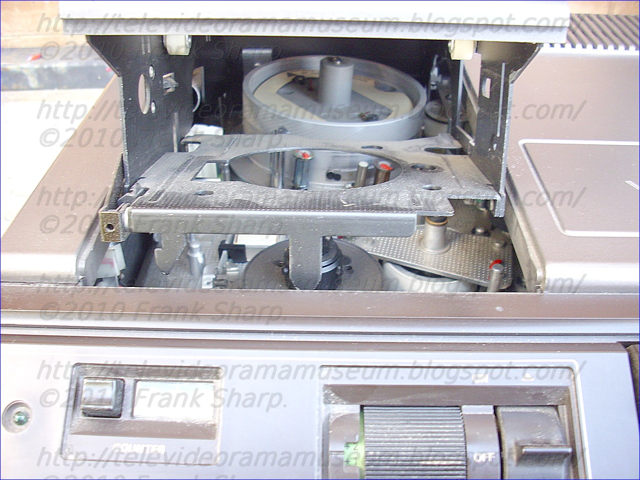


 unts
as a big step that is definitely changing the profile of the
company. Philips was one of few companies that successfully made the
transition from the electrical world of the 19th century into the
electronic age, starting its semiconductor activity in 1953 and
building it into a global top 10 player in its industry. As such,
Semiconductors was at the heart of many innovations in Philips over
the past 50 years.
unts
as a big step that is definitely changing the profile of the
company. Philips was one of few companies that successfully made the
transition from the electrical world of the 19th century into the
electronic age, starting its semiconductor activity in 1953 and
building it into a global top 10 player in its industry. As such,
Semiconductors was at the heart of many innovations in Philips over
the past 50 years. The
foundations of Philips were laid in 1891 when Anton and Gerard
Philips established Philips & Co. in Eindhoven, the
Netherlands. The company begun manufacturing carbon-filament lamps
and by the turn of the century, had become one of the largest
producers in Europe. Stimulated by the industrial revolution in
Europe, Philips’ first research laboratory started introducing its
first innovations in the x-ray and radio technology. Over the years,
the list of inventions has only been growing to include many
breakthroughs that have continued to enrich people’s everyday lives.
The
foundations of Philips were laid in 1891 when Anton and Gerard
Philips established Philips & Co. in Eindhoven, the
Netherlands. The company begun manufacturing carbon-filament lamps
and by the turn of the century, had become one of the largest
producers in Europe. Stimulated by the industrial revolution in
Europe, Philips’ first research laboratory started introducing its
first innovations in the x-ray and radio technology. Over the years,
the list of inventions has only been growing to include many
breakthroughs that have continued to enrich people’s everyday lives. Gerard
Leonard Frederik Philips (October 9, 1858, in Zaltbommel – January
27, 1942, in The Hague, Netherlands) was a Dutch industrialist,
co-founder (with his father Frederik Philips) of the Philips Company
as a family business in 1891. Gerard and his younger brother Anton
Philips changed the business to a corporation by founding in 1912 the
NV Philips' Gloeilampenfabrieken. As the first CEO of the Philips
corporation, Gerard laid with Anton the base for the later Philips
multinational.
Gerard
Leonard Frederik Philips (October 9, 1858, in Zaltbommel – January
27, 1942, in The Hague, Netherlands) was a Dutch industrialist,
co-founder (with his father Frederik Philips) of the Philips Company
as a family business in 1891. Gerard and his younger brother Anton
Philips changed the business to a corporation by founding in 1912 the
NV Philips' Gloeilampenfabrieken. As the first CEO of the Philips
corporation, Gerard laid with Anton the base for the later Philips
multinational. Anton
Frederik Philips (March 14, 1874, Zaltbommel, Gelderland – October
7, 1951, Eindhoven) co-founded Royal Philips Electronics N.V. in 1912
with his older brother Gerard Philips in Eindhoven, the Netherlands.
He served as CEO of the company from 1922 to 1939.
Anton
Frederik Philips (March 14, 1874, Zaltbommel, Gelderland – October
7, 1951, Eindhoven) co-founded Royal Philips Electronics N.V. in 1912
with his older brother Gerard Philips in Eindhoven, the Netherlands.
He served as CEO of the company from 1922 to 1939.


