
A tape loading apparatus is employed in a recording and/or
reproducing apparatus including, a guide drum having at least one head
for recording or reproducing a signal on or from a tape. The tape
loading apparatus comprises endless belt-shaped members provided side by
side on both sides of the guide drum so that each endless belt-shaped
member has one straight portion extending between the guide drum and a
cassette, driving mechanism for driving the endless belt-shaped members
so that the endless belt-shaped members travel in a direction towards
the guide drum upon loading mode, and travel in a direction towards the
cassette upon unloading mode, a pair of tape guiding mechanisms for
guiding the tape so that the tape travels along a predetermined tape
travelling path throughout a predetermined range with respect to the
guide drum at a predetermined position, by locking the tape and moving
in accordance with the travel of each endless belt-shaped member from a
position inside the cassette to the predetermined position adjacent the
guide drum upon loading mode, a pair of stopping members fixed at the
above predetermined position, guiding path mechanism for guiding the
pair of tape guiding mechanism so that the tape guiding mechanisms move
along a predetermined path, and supporting and holding mechanism for
supporting and holding the tape guiding mechanism at the above
predetermined position by pushing against the stopping members to urge
the tape guiding mechanism in a direction identical to the moving
direction upon loading mode, after the tape guiding mechanism has
reached the above predetermined position by moving along the guiding
path mechanism.
The present invention generally relates to tape loading apparatuses
in recording and/or reproducing apparatuses, and more particularly to a
tape loading apparatus which accurately and stably maintains a
predetermined tape travelling path, by positively supporting and
holding, at a predetermined position, a member for pulling a tape out
from a cassette to load the tape onto a predetermined tape travelling
path in a recording and/or reproducing apparatus.
Conventionally,
as an apparatus for loading a magnetic tape accommodated within a
cassette which is loaded onto a predetermined position of a magnetic
recording and/or reproducing apparatus, by pulling the magnetic tape
outside from the cassette and loading the magnetic tape onto a
predetermined tape travelling path of the magnetic recording and/or
reproducing apparatus, there was a device in which a rotary ring for
surrounding a guide drum provided with rotary magnetic h
eads, is
provided. In this apparatus, a pole embeddedly provided on the ring
engages to and pulls out the magnetic tape outside from the cassette
upon rotation of the ring, to load the tape onto a predetermined tape
travelling path. However, in this conventional apparatus, the
construction of the tape loading apparatus is complex, since the ring
having a large diameter must be rotated outside of the guide drum.
Furthermore, this conventional apparatus was especially disadvantageous
in that it was difficult to apply the apparatus to a magnetic recording
and/or reproducing apparatus for home use because of the complex
construction and the large size of the apparatus.
In addition, as
another conventional tape loading apparatus, there was an apparatus
provided with a pair of tape pulling-out mechanisms respectively having a
tape pulling-out pole. Each of the above pair of tape pulling-out
mechanisms of the conventional apparatus comprises a pair of levers
respectively rotatable in mutually opposite directions where the pair of
levers are respectively provided with a tape pulling-out pole
embeddedly fixed to the tip end thereof, a pair of locking members for
locking the tape pulling-out poles provided on these levers at
predetermined rotated positions, and a pair of pushing levers for
supporting and holding the tape pulling-out poles at locked positions by
rotating and pushing the poles from the rear against the locking
members, after the poles have rotated to positions where the poles are
to be locked by the locking members. Further detailed description of the
construction of this conventional apparatus is given in the U.S. Pat.
No. 4,138,699 of which the assignee is the same Victor Company of Japan, Ltd. (Yokohama, JP) as that of the present
application.
However, in this conventional apparatus, the
construction of the apparatus is complex since two pairs of levers are
used, and a large space is required for the rotating range. Further, it
becomes necessary to position these pairs of levers provided on the
poles at differing heights so that the levers do not make contact with
each other, because these levers are in an intercrossing state on the
plan view. Accordingly, the construction of the apparatus becomes
complex, and was disadvantageous in that the adjusting operation upon
assembling of the apparatus is troublesome.
SHARP VC-6300S Automatic tape loading type recording and/or reproducing apparatus:
An automatic tape loading type recording and/or reproducing apparatus
employs a guide drum having heads for recording or reproducing signals
on or from a tape. A pair of tape guides engage the tape, as it is
moving in the vicinity of the guide drum, and guide it along a specific
tape travel path, over a specific angular expanse of the guide drum. The
tape guides move in a specific direction to a specific position at the
time of loading, and move, in the reverse direction, from the specific
position at the time of unloading. A checking means contacts the tape
guides which have been moved to the specific position and prevents a
displacement of the tape guides in a reverse direction, during recording
or reproducing mode of operation.
1. An automatic tape loading type recording and/or reproducing apparatus comprising:
a guide drum having heads for recording or reproducing signals on or from a tape;
a pair of tape guide means for engaging said tape, said tape guide
means moving to a specific position in the vicinity of said guide drum
where said tape is fully loaded, said guide means guiding the tape at
said specific position in a manner such that the tape travels along a
specific tape travel path and over a specific angular expanse with
respect to the guide drum;
means responsive to a loading
operation for moving said tape guide means in a specific direction to
said specific position when the tape is loaded into said specific tape
travel path and responsive to an unloading operation for moving the tape
guide means in the reverse direction away from said specific position
when the tape is removed from the specific tape travel path; and
checking means for contacting the tape guide means while in said
specific position and preventing displacement of the tape guide means in
said reverse direction during either recording or reproducing mode of
operation.
2. An automatic tape loading type recording and/or
reproducing apparatus as claimed in claim 1 which further comprises stop
members for respectively stopping said tape guide means while in said
specific position to prevent further movement of the tape guide means in
said specific direction, and said checking means comprises pressing
members for pressing the tape guide means against said stop members.
3. An automatic tape loading type recording and/or reproducing apparatus comprising: a guide drum having heads for recording or reproducing signals on or from a tape;
a pair of tape guide means for engaging said tape, said guide means
moving to specific positions in the vicinity of said guide drum, said
guide means guiding the tape at said specific positions in a manner such
that the tape travels along a specific tape travel path and over a
specific angular expanse with respect to the guide drum;
means
responsive to a loading operation for moving said tape guide me
ans in
specific directions to said specific positions when the tape is loaded
into said specific tape travel path and responsive to an unloading
operation for moving the tape guide means in the reverse directions away
from said specific positions when the tape is removed from the specific
tape travel path;
stop members for respectively stopping said
tape guide means while in said specific positions to prevent further
movement of the tape guide means in said specific directions; and
checking means including pressing members for abutting the tape guide
means and urging said guide means to press the tape guide means in said
specific directions while in said specific positions in order to prevent
displacement of the tape guide means in said reverse directions during
either a recording or a reproducing mode of operation.
4. An automatic tape loading type recording and/or
reproducing apparatus as claimed in claim 3 in which said checking means
are normally held in positions where they are removed from the paths of
movement of said tape guide means and where they do not obstruct the
positional movement of the tape guide means, and means for positionally
moving the checking means in follow-up action to the movement of the
tape guide means.
5. An automatic tape loading type recording and/or
reproducing apparatus as claimed in claim 3 which further comprises
means for moving with said checking means and operating, when the
checking means reach positions to check said tape guide means, by making
contact with the tape loaded into said specific tape travel path by the
tape guide means.
6. An automatic tape loading type recording and/or
reproducing apparatus as claime
d in claim 5 in which said means for
making contact with the tape includes heads and an impedance roller.
7. An automatic tape loading type recording and/or
reproducing apparatus as claimed in claim 3 in which each of said tape
guide means comprises a base structure means mounted to undergo
rotational displacement and guide pole means erected on said base
structure means, and said guide pole means being pressed against said
stop members responsive to operation of said pressing members, whereby
the rotational displacement positions of the guide pole means are
determined.
8. An automatic tape loading type recording and/or
reproducing apparatus as claimed in claim 7 in which said guide pole
means comprise an upright guide pole and an inclined guide pole erected
on said base structure means, and said inclined guide pole is pressed
against said stop members by said pressing members.
Description:
BACKGROUND OF THE INVENTION
The present
invention relates generally to an automatic tape loading recording
and/or reproducing apparatus, and more particularly to an apparatus in
which a tape is automatically loaded by guide poles. Moreover, the
traveling tape is thereafter guided in a stable manner.
Heretofore,
automatic tape loading type recording and/or reproducing apparatus had a
tape which is automatically engaged by guide poles and drawn out of a
cassette. The tape is loaded into a specific tape travel path around a
guide drum. In an apparatus of this type, the guide for loading the tape
determines the range of the angle with which the tape is in wrapping
contact with the guide drum. At the same time, these poles guide the
traveling tape.
In an automatic tape loading type recording
and/or reproducing apparatus of this type, the guide poles are adapted
to move positionally at the time of tape loading. They are not fixed, as
in a recording/reproducing apparatus which does not have automatic tape
loading. For this reason, there is a possibility of some displacement
of the guide poles even at the positions which they reach upon
completion of the tape loading operation in comparison with a fixed tape
of guide poles.
For this reason, when an excessive tension is
imparted to the tape at the time of recording or reproducing, there is
the possibility that the guide poles will undergo an unnecessary
displacement, in the unloading direction, from their proper positions.
If the guide poles are unnecessarily displaced in this manner, upon the
completion of loading, the tape travel will become unstable around the
guide drum even when this displacement is extremely small. This
displacement will give rise to the serious problem of defective
recording or reproducing.
Furthermore, the tape travel path
around the cylindrical surface of the guide drum is determined by the
positions of these guide poles. Accordingly, for the tape to travel
along its correct travel path, it is necessary for the guide poles to
have the correct positions, orientations, and other features. However,
if the guide poles are positionally movable as mentioned above, their
positions, orientations, and other features tend to become inaccurate
upon the completion of tape loading.
SUMMARY OF THE INVENTION:
Accordingly,
it is a general object of the present invention to provide a novel and
useful automatic tape loading recording and/or reproducing apparatus in
which the above described problems have been overcome.
Another
object of the invention is to provide an automatic tape loading type
recording and/or reproducing apparatus having means for suppressing
positional movement of loading means, for loading a tape in wrapping
contact around the cylindrical surface of parts such as rotating heads.
Movement suppression is from the position of the guide poles at the
completion of loading. The suppression prevents movement in the
unloading direction. By this suppression, the tape is caused to travel
stably in wrapping contact around the guide drum, which contains
rotating magnetic heads, even when the tape tension fluctuates during
tape travel.
A further object of the invention is to provide an
automatic tape loading type of recording and/or reproducing apparatus in
which the loading means is displaceably supported for shifting the
loading means. The loading means is accurately positioned relative to
the guide drum, at the completion of the loading operation, irrespective
of some dimensional errors, deformations, and other conditions of the
loading mechanism. The travel path of the tape is held in constant
wrapping contact around the guide drum surface.
Other objects and
features of the present invention will be apparent from the following
detailed description set forth in conjunction with the accompanying
drawings.
BRIEF DESCRIPTION OF THE DRAWINGS
In the drawings:
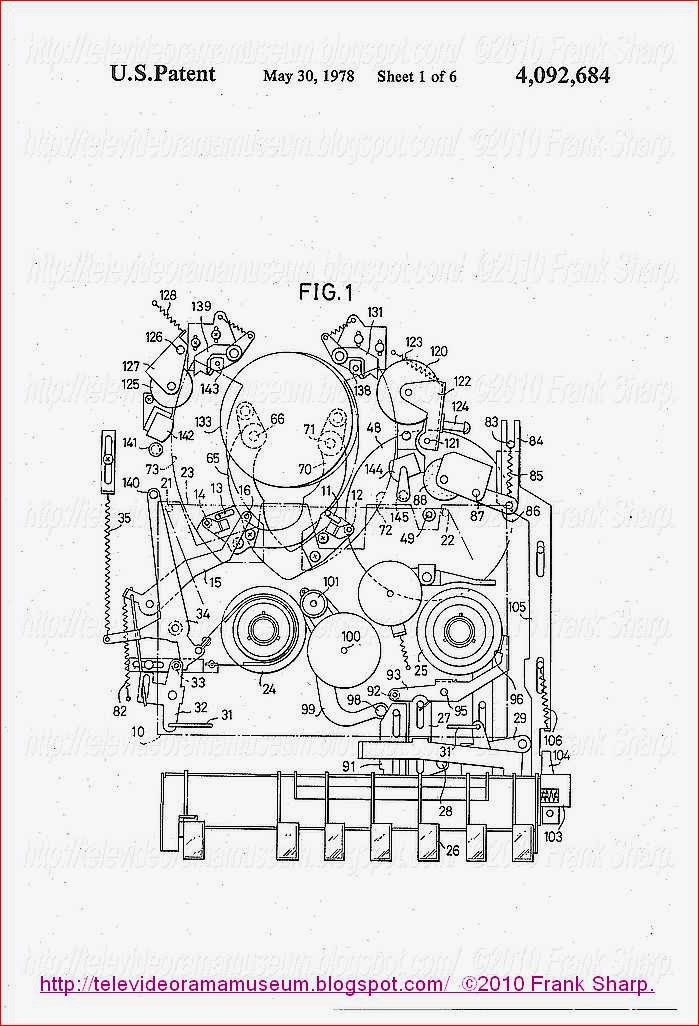
FIG.
1 and FIG. 2 are plan views respectively showing one embodiment of an
automatic tape loading type recording and/or reproducing apparatus,
according to the present invention, with the apparatus shown in a stop
mode and in a state after tape loading has been completed;
FIG. 3
is a plan view showing mechanical parts for driving a tape loading
mechanism and related mechanisms in the apparatus illustrated in FIGS. 1
and 2;
FIG. 4 is a plan view showing the tape loading mechanism which is actuated by the mechanism parts shown in FIG. 3;
FIG.
5 and FIG. 6 are elevation views, respectively showing a guide pole
engagement or clamping mechanism, as viewed in the arrow directions V
and VI in FIG. 2;
FIGS. 7A and 7B are enlarged plan views
respectively showing a clamp arm mechanism for clamping a supply side
guide pole in the unoperated and operated states;
FIGS. 8A and 8B
are enlarged plan views respectively showing a clamp arm mechanism for
clamping a take-up side guide pole in the unoperated and operated
states;
FIG. 9 is an elevation view of a guide pole mechanism, as viewed in the arrow direction IX in FIG. 1; and
FIG. 10 is an enlarged vertical section taken along the line X--X in FIG. 9 .
DETAILED DESCRIPTION
Upon
recording or reproducing, a cassette (or cartridge) 10 is placed in a
loading position in the recording/reproducing apparatus, as indicated by
two-dot chain line in FIG. 1.
A pair of up-right guide rollers
11 and 12, a pair of inclined guide poles 13 and 14, a tension pole 15,
and a capstan 16 respectively enter into an opening in the bottom of the
cassette 10 and fit into the interior thereof. These members are
disposed on the inner side of the tape, that is, on the side confronting
the non-magnetic side of the tape. Guide poles 19 and 20 guide a tape
22 in its span between a tape supply roll 17 and a take-up roll 18. The
magnetic surface of the tape faces the front of the cassette 10.
When
the cassette 10 is placed in its operational position, a supply reel
and a take-up reel (neither being shown) respectively fit onto a supply
side reel disc 23 and a take-up side reel disc 24 contained within the
cassette 10. The tape rolls 17 and 18 are respectively wound on these
reels.
A cylindrical guide drum 25 comprises an upper rotating
drum carrying rotating video heads and a lower drum fixed to a guide
drum base 27. The base 27 is fixed to a chassis 26 by screws, at a
specific position. A first position defining member 28 and a second
position defining member 29 are respectively fixed, by screws, to the
guide drum base 27, on opposite sides of the drum 25. The first position
defining member 28 has stop members 30a and 30b, and a guide member 32
projecting therefrom. The stop members 30a and 30b have V-shaped grooves
for engaging the inclined guide pole 13 at the upper and lower ends
thereof, as indicated in FIG. 5, when the loading has been completed.
The guide member 32 operates, as indicated in FIG. 6, to define the
height position of a reference pin 31 described hereinafter, at the
completion of the loading. The second position defining member 29 also
has stop members 33a and 33b formed with V-shaped grooves for engaging
the inclined guide pole 14. A guide member 35 defines the height
position of a reference pin 34 engaged therein. The members 33a, 33b,
and 35 project from the member 29.
In the stop mode of the
apparatus, a pair of clamp arms 40a and 40b are retracted, together with
an impedance roller 41, an erasing head 42, and a guide roller 43. The
retracted positions are outside of the moving path (indicated by
single-dot chain line l in FIG. 1) of the guide roller 11 and the guide
pole 13 during the loading mode. Another pair of clamp arms 44a and 44b
are also retracted, together with an impedance roller 45, to positions
outside of the moving path (indicated by single-dot chain line m in FIG.
1) of the guide roller 12 and the guide pin 14 during the loading mode.
When a PLAY button 50 is pushed, a motor (not shown) is started.
A fly-wheel 53 and the capstan 16 rotate unitarily in the clockwise
direction, and a drive pulley 57 rotates in the counterclo
ckwise
direction. As another result of the manipulation of the PLAY button 50, a
roller 60 and a brake shoe 62 respectively separate from the reel discs
23 and 24, which are thereupon released from their braked state.
On
the other hand, when the PLAY button 50 is pressed, a movement is
transmitted through an intercoupling mechanism to rotate a lever 70
(FIG. 3),
in the clockwise direction. A lever 71 is released from its
locked state when a pin 72 on the lever 70 is moved away. Lever 71 is
rotated counterclockwise about a shaft 74 responsive to the force of a
spring 73. This causes a gear 75, rotatably supported on the distal end
of the lever 71, to mesh with a gear 76 mounted coaxially with the
capstan 16. As a consequence, the rotation of the gear 76 is transmitted
by way of the gear 75 and gears 77 and 78 to a gear 79, in a speed
reduced state.
As the gear 79 rotates counterclockwise, an
approximately fan shaped cam structure 80 is compulsorily rotated
clockwise, with respect to a shaft 82. Its surface 80a is guided by an
actuating pin 81 which is fixed to the lower surface of the gear 79.
When the gear 79 has rotated through approximately one half revolution,
it is locked by the action of a circular cam structure 83 and a roller
84. At the same time, the lever 70 is rotated counterclockwise by a
mechanism not shown, and the gear 75 separates from the gear 76.
Furthermore, the cam structure 80 reaches its final rotational position
as indicated by the single-dot chain line in FIG. 4.
Together
with the rotation of the cam structure 80 to the vicinity of the final
rotational position, a rotating lever 87 is rotated counterclockwise
about a shaft 88. The rotation is caused by a pair of coupling levers
86a and 86b which are connected by a spring 85. As a consequence of the
rotation imparted to the lever 87, a coupling member 90 and an arm 91
cause a rotating lever 89 to rotate clockwise about a shaft 92.
Simultaneously, a coupling member 94 causes another rotating lever 93 to
rotate counterclockwise about a shaft 95. The levers 89 and 93 rotate
to positions indicated by the single-dot chain line in FIG. 4, that is,
to the positions indicated in FIG. 2.

The rotating levers 89 and 93 are
still urged to rotate in the loading direction, as a result of the
tensile force of the spring 85. The inclined guide pole 13 is pressed
into contact with the V-shaped grooves of the stop members 30a and 30b.
The inclined guide pole 14 is pressed into contact with the V-shaped
grooves of the stop members 33a and 33b.
As a consequence of the
rotation of the pair of rotating levers 89 and 93, the magnetic tape 22
is drawn out of the cassette 10. The tape is intercepted and engaged by
the guide rollers 11 and 12, and the guide poles 13 and 14. The tape is
wrapped over a specific angular expanse of the guide drum 25.
During
this tape loading operation, the impedance rollers 41 and 45 are still
in their retracted positions. The guide rollers 11 and 12 move smoothly
without colliding with the impedance rollers 41 and 45.
At an
intermediate point in the tape loading operation, the tension arm 96 is
released from its engaged state. The arm 96 is turned counterclockwise
about a shaft 98 responsive to the tensile force of a spring 97. As a
consequence, the tension pole 15 is extracted from the cassette and it
makes contact with the magnetic tape 22. A brake band 99 is tightened,
to operate a tension servo mechanism.
A mechanism for clamping
the guide pole 13 comprises, as indicated in FIG. 1 and FIG. 7A, an
actuating arm 100, an arm 102 for supporting the impedance roller 41,
the erasing head 42, and other parts, and a clamp arm 101 having the
pair of arms 40a and 40b at the distal end thereof. The arms 100 and 102
are pivoted independently on a pin 103. The arm 101 is held by the
up-right side surface of the actuating arm 100. Moving as a whole, the
arms 100, 102, and 101 are rotated in the clockwise direction responsive
to a spring 122. A projecting part 101a of the clamp arm 101 is engaged
by the free end of a leaf spring 104. The proximal part of spring 104
is fixed to the actuating arm 100 by a screw.

The leaf spring 104 is
contacted, at approximately the middle part thereof, by a projection
100a of the arm 100. The support arm 102 is urged to rotate
counterclockwise responsive to the tensile force of a spring 105 which
is stretched between a bent part 102a and a bent arm 100b of the
actuating arm 100. However, the rotation of arm 102 is limited by being
engaged at a side part thereof by the bent arm 100b. The impedance
roller 41 and related parts are retracted.
Another mechanism for
clamping the guide pole 14 comprises, as indicated in FIG. 1 and FIG.
8A, an actuating arm 106, and an arm 108 for supporting the impedance
roller 45. The arms 106 and 108 are independently pivoted on a shaft
109. A clamp arm 107 which has a pair of clamp arms 44a and 44b is held
by the vertical side of the actuating arm 106. These parts are rotated,
as a whole, in the counterclockwise direction. A projecting part 107a of
the clamp arm 107 engages the free end of a leaf spring 110, the
proximal part of which is fixed by screws to the actuating arm 106. The
leaf spring 110 is contacted at approximately the middle part thereof by
a projection 106a of the arm 106. The support arm 108 is urged to
rotate clockwise responsive to a spring 111. However, its rotation is
limited by the bent part of the arm 106, whereby the impedance roller 45
is held at a retracted position.
When the cam structure 80
rotates further, to its terminal position, a
roller 116 supported on an
L-shaped arm 115 shown in FIG. 4 is guided by an inclined cam surface
80b of the cam structure 80. The arm 115 rotates counterclockwise about a
pin 117. This rotation of the arm 115 is transmitted through a coupling
arm 118 to cause another L-shaped arm 119 to rotate clockwise about a
pin 120.
As a result of the rotation of the L-shaped arm 119, the
actuating arm 100 is engaged and guided by the roller 121. Arm 100
rotates counterclockwise to its position indicated in FIG. 2, which is
counter to the force of the spring 122. Interrelatedly with the rotation
of the arm 100, the clamp arm 101 and the support arm 102 rotate
counterclockwise. The support arm 102 is limited in its rotation at a
position where it presses against a stop member 123 on the chassis. Arm
100 is still urged to rotate counterclockwise by the spring 105. The
impedance roller 41, the erasing head 42, and the guide roller 43
thereby contact the tape 22 drawn out of the cassette, as indicated in
FIG. 2.

By this arrangement a loading mechanism is simply
constructed. The members which are necessary for recording and/or
reproducing operations, such as the erasing head 42, move to their
operational positions. There, they make contact with the tape 22 and
rotate the engagement arm 101. Moreover, an, overall miniaturization of
the apparatus is accomplished. In addition, the tape path becomes a
simple loop at the time of recording and/or reproducing.
Moreover,
the clamp arms 40a and 40b of the clamp arm 101 abut against the
inclined guide pole 13 which has been pressed against the stop members
30a and 30b, respectively, as indicated in FIG. 5. The arm 100 is
further caused to rotate thereafter. The clamp arm 101 is, therefore,
subjected to a relatively large rotational force in the counterclockwise
direction, as a result of the spring force of the leaf spring 104.
Spring 104 is compulsorily deformed by the rotation of the arm 100, as
indicated in FIG. 7B. As a consequence, while it is pressed against the
stop members 33a and 33b, the inclined guide pole 14 is engaged and
clamped at its upper end and its lower end by the clamp arms 40a and
40b. These arms are positioned at opposite sides of the magnetic tape
22. Guide pole 13 is pressed in the loading direction indicated by the
arrow Z in FIG. 2 and FIG. 7B. Thus, the guide pole 13 is prevented from
movement in the unloading direction and is positively positioned at the
proper position.
Moreover, as a result of the above described
counterclockwise rotation of the L-shaped arm 115, the actuating arm 106
is engaged and guided by the roller 124. Arm 115 rotates clockwise to
its position indicated in FIG. 2. Interrelatedly with the rotation of
the arm 106, the clamp arm 107 and the support arm 108 rotate clockwise.
The support arm 108 is limited in its rotation at a position where it
presses against a stop member 125 on the chassis. There, the arm 108 is
still urged to rotate clockwise by a spring 111. The impedance roller 45
thereby contacts the tape 22 drawn out of the cassette as indicated in
FIG. 2.
The clamp arms 44a and 44b of the clamp arm 107 abut
against the inclined guide pole 14 which has been pressed against the
stop members 33a and 33b, respectively. The arm 106 is further caused to
rotate thereafter. To the clamp arm 107 is imparted a relatively large
rotational force in the clockwise direction as a result of the spring
force of the leaf spring 110, which is compulsorily deforme
d by the
above rotation of the arm 106, as indicated in FIG. 8B. As a
consequence, while it is pressed against the stop members 33a and 33b,
the inclined guide pole 14 is engaged and clamped at its upper end and
the lower end thereof by the clamp arms 44a and 44b which are positioned
at opposite sides of the magnetic tape 22. Guide pole 14 is pressed in
the loading direction, indicated by the arrow Y, in FIG. 2 and FIG. 8B.
Thus, the guide pole 14 is prevented from movement in the unloading
direction and is positively positioned at the proper position.
Accordingly,
following the loading operation in the recording or reproducing mode
the guide poles 13 and 14 are engaged or clamped by the clamp arms 40a,
40b, 44a, and 44b, despite a force acting in the unloading direction due
to the tension of the traveling magnetic tape 22. Thus, the poles
positively restricted against any movement thereof in the unloading
direction. As a result, the traveling path of the magnetic tape 22 is
kept secure on the inlet side and the outlet side with respect to the
guide drum 25 in the tape traveling direction. Furthermore, since the
guide poles 13 and 14 are pressed against the stop members 30a, 30b, 33a
and 33b, they are held at their proper positions in a stable manner
without even a very minute movement, due to the fluctuation of the tape
tension. As a result, in the recording or reproducing mode, the magnetic
tape 22 travels around the cylindrical surface of the guide drum 25,
over a specific angular expanse, and along a specific travel path.
Moreover,
the rotation of the arm 115 in the counterclockwise direction causes
slide levers 130 and 131 to move in the arrow direction A. These slide
levers are disposed on the chassis in a mutually intercoupled state. As a
result of this movement of the slide lever 130, a pinch roller
supporting arm 132 is rotated in the counterclockwise direction about a
pin 134, by a large tensile force of a spring 13
3. Thereupon, a pinch
roller 135 is pressed against the capstan 16, clamping the magnetic tape
22 therebetween. Moreover, as a result of the movement of the slide
lever 131, the drive roller 57 is pressed into contact with the take-up
reel disc 24.
Upon completion of the automatic tape loading, the
tape 22 is drawn from the tape roll 17 on the tape-supply side past
tension poles 15, and passed over a guide pole 43, and a full-width
erasing head 43. Thereafter, it comes into contact with the impedance
roller 41. The height position of the tape 22 is determined by the guide
roller 11. The tape 22 is further guided and changed in direction by
the guide pole 13. The tape 22 is held in a wrapping helical contact
around the guide drum 25. While the tape 22 is thus held in wrapping
contact, a video signal is recorded or reproduced by the rotating video
heads.
After leaving the guide drum 25, the tape 22 is guided,
positioned, and changed in direction by the guide pole 14 and the guide
roller 12. Then, after contacting the above described impedance roller
45, the tape 22 contacts an audio and control signal recording and
reproducing head 36. The tape 22 is thereafter clamped between and
driven by the pinch roller 135 and the capstan 16. Then, it enters the
cassette 10 and is wound on the tape roll 18.
The magnetic tape
22 travels stably around a specific angular expanse of the cylindrical
surface of the guide drum 25. The specific tape path is defined by the
pair of guide poles 13 and 14, without being influenced by fluctuations
of the tape tension. Further, very minute fluctuations in the tape
traveling speed are suppressed by the inertial rotation of the impedance
rollers 41 and 45. Thus, the tape travel is rendered remarkably stable.
Next, the structure and operation of a guide pole mechanism will be described with further reference to FIG. 9 and FIG. 10.
A
movable base structure 140 supports the guide roller 11. The guide pole
13 is loosely fitted to a bracket 141 which is fixed by screws to a
distant end of rotating lever 89. Lever 89 is displaceable within a
specific range. An annular spacer 143 is fixed to the movable base
structure 140 by a screw 142 which has a longitudinal dimension t
1 that is larger than the thickness dimension t
2
of the bracket 141. The spacer 143 is loosely fitted in an opening 144
formed in the bracket 141. The above described mechanism thereby allows
the movable base structure 140 to undergo rotational displacement about
screw 142, as indicated by the arrow S. Rotational displacement is in
the arrow direction T within a specific angular range, and displacement
is in the linear direction, as indicated by the arrow U. These
displacements are effected by movement of the spacer 143 inside of the
opening 144 in a manner such that the spacer 143 is prevented from
disengaging the opening 144, by a washer 145. The movable base structure
140 is allowed to undergo the above described rotational displacement
in the arrow direction S, within a specific angular range defined by a
pair of projections 146a and 146b, above and below the bracket 141.
Accordingly,
in the loading mode the guide roller 11 and the guide pole 13 draw out
the tape 22 with an inclination about the support part of the movable
base structure 140. The inclination is in any direction according to the
tension of the magnetic tape 22 as it is drawn out of the cassette.
Therefore, the tape 22 is drawn out of the cassette without an excessive
force being applied thereto.

Furthermore, when the loading is
completed, the movable base structure 140 reaches the position as
indicated in FIG. 2. The reference pin, fixed to the side of the base
structure 140, enters the V-shaped groove 37 of the guide member 32 for
defining a height position, as indicated in FIG. 6 (or by the two-dot
chain line in FIG. 9). As the pin 31 enters the groove 37, the movable
base structure 140 rotates in the arrow direction S to a predetermined
position. The height position of the vertical guide roller 11 determines
the position of the guide roller 11 flanges, which guide the edges of
the tape.
Moreover, upon the completion of the tape loading, the
inclined guide pole 13 is engaged within the V-shaped grooves of the
stop members 30a and 30b. There is a rotational displacement of the
movable base 140 mainly in the arrow direction T. Guide pole 13 is
positioned in the predetermined, inclined direction where it is pressed
into the V-shaped grooves by the clamp arms 40a and 40b, as indicated in
FIG. 5.
Another movable base structure 150 has the guide roller
12 and the guide pole 14 mounted on a bracket 151, which is fixed by
screws on the end of rotating lever 89. Accordingly, upon the completion
of tape loading, the height of the upright guide roller 12 is defined
by the engagement of the reference pin 34 within the V-shaped groove 38
of the guide member 35. The guide pole 14 is positioned by the
coope
ration of the stop members 33a and 33b and the clamp arms 44a and
44b.
For this reason, even if the tape loading mechanism is not
assembled with the same high precision that was known heretofore, the
guide rollers 11, 12, and the guide poles 13, 14 are set accurately at
their proper positions after completion of the tape loading. Moreover,
even if there are defects, such as deformations after long years of use,
the set positions of the guide rollers 11 and 12 and the guide poles 13
and 14 do not change at the completion of the tape loading. These
positions are maintained as in the initial operation. Therefore the tape
travel path around the guide drum is held correctly, along the proper
travel path. Accordingly, interchangeability of the apparatus is
afforded over a long period of time. The complicated adjusting work
heretofore required at the time of assembling is substantially
eliminated. Thus, the assembling of the apparatus is facilitated.
When
the STOP button 153 is manipulated during reproduction the PLAY button
50 is returned to its original position. The gear 79 rotates through
approximately one half revolution, which is similar to the operation
which occurs when the PLAY button is pressed. The cam structure 80
rotates counterclockwise to its position indicated by the full line in
FIG. 4.
As a result of the return action of the cam structure 80, the
mechanisms operated in the tape loading mode are operated in the order
and directions which are reverse to those in the loading mode. In the
unloading mode, roller 61 winds the magnetic tape 22, which has been
drawn out of the cassette, around the supply tape roll 17. The tape is
thus accommodated within the cassette.
The apparatus of the
present invention may also be adapted so that the above described guide
rollers 11, 12 and the guide poles 13, 14 intercept the tape as it is
being drawn out of the cassette by other means, and thereafter to move
so as to load the tape in a wrapping contact with the guide drum.
Furthermore,
the apparatus of the present invention may be so adapted that the clamp
arms 40a, 40b, 44a, and 44b are merely locked at their operational
positions so as to prevent unnecessary movement of the guide poles 13
and 14 in the unloading direction. In addition, the mechanism for
supporting the guide rollers 11 and 12 and the guide poles 13 and 14 is
not limited to that shown and described in the above described
embodiment of the invention. The guide rollers and poles may be
supported so as to be displaceable by a certain degree, with respect to
the loading arm, by appropriate mechanisms using springs and the like.
Further,
this invention is not limited to these embodiments. Variations and
modifications may be made without departing from the scope and spirit of
the invention.
SHARP VC-6300S Automatic loading video recorder with speed stabilizing:
A video signal recording and/or reproducing apparatus comprises a guide
drum having at least one rotating head for recording and/or reproducing
video signals. Tape is drawn from within a cassette and loaded into a
specific tape travel path including a part wherein the tape is in
wrapping contact with a part of the guide drum. At least one impedance
roller contacts the tape loaded in the predetermined tape travel path.
The impedance roller is in the vicinity of a position where a loading
means completes the loading.
1. A video signal recording and/or reproducing apparatus comprising:
a guide drum having at least one rotating head for recording and/or reproducing video signals;
loading means for drawing out a tape accommodated within a cassette
and loading said tape in a specific tape travel path including a part
wherein the tape is in wrapping contact with a predetermined arcuate
portion of said guide drum; and
at least one impedance roller
having a peripheral portion making contact with the tape thus loaded in
said predetermined tape travel path and rotating with a peripheral speed
equal to a travel speed of the tape in said predetermined tape travel
path, thereby stabilizing the travel speed of the tape responsive to a
rotational inertia of the impedance roller.
2. A video signal recording and/or reproducing
apparatus as claimed in claim 1 and means for moving said impedance
roller into the vicinity of said loading means responsive to a
completion of the loading operation.
3. A video signal recording and/or reprod
ucing
apparatus as claimed in claim 1 which further comprises: holding means
for holding said impedance roller in a freely rotatable manner , means
for displacing the impedance roller between a tape-contacting position
in the predetermined tape travel path and a retracted
non-tape-contacting position; and biasing means for urging said holding
means in a direction of movement away from said retracted position and
toward said contacting position, and means responsive to a tape loading
operation for temporarily retracting said impedance roller so that it
does not interfere with the loading operation of said loading means.
4. A video signal recording and/or reproducing
apparatus as claimed in claim 1 which further comprises: means for
adjusting the position at which said impedance roller contacts the tape;
and a control head for recording or reproducing a control signal on or
from the tape, said impedance roller being located in said predetermined
tape travel path at a position between said guide drum and said control
head.
5. A video signal recording and/or reproducing apparatus comprising: a guide drum having at least one rotating head for recording and/or reproducing video signals;
loading means having a pair of tape loading and guiding means for
drawing a tape from a cassette accommoating a supplyside tape roll and a
takeup-side tape roll, loading the tape in a predetermined tape travel
path wrappingly contacting a predetermined arcuate portion of the
surface of said guide drum, and guiding the tape after loading;
erasing head means operative during recording and located in said tape
travel path between one of said tap loading and guiding means and said
supply-side tape roll for erasing previously recorded signals, prior to a
recording of the video signals;
tape driving means in said
tape travel path between the other tape loading and guiding means and
said takeup-side tape roll for driving the tape along said tape travel
path;
control head means for recording and/or reproducing
control signals on or from said tape while in said travel path between
said other tape loading and guiding means and said tape driving means;
and
first and second impedance roller means having peripheral
portions making contact with the tape loaded in said predetermined tape
travel path and rotating with a peripheral speed equal to a travel speed
of the tape in said predetermined tape travel path for stabilizing the
tape travel speed responsive to the rotational inertia of the first and
second impedance roller means, the first impedance roller means being
located in said tape travel path between said one tape loading and
guiding means and said erasing head means, the second impedance roller
means being located in said tape travel path between said other tape
loading and guiding means and said control head means.
6. A video signal recording and/or reproducing
apparatus as claimed in claim 5 which further comprises: holding means
for holding said first and second impedance roller means in a freely
rotatable manner; means for displacing the impedance roller means
between tape contacting positions in said specific tape travel path and
retracted positions removed from said tape contacting positions; driving
means for causing said holding means to retract said impedance roller
means from the path of said loading means during the loading operation
and for moving said impedance roller means to said tape contacting
positions responsive to a completion of the loading operation.
Description:
BACKGROUND OF THE INVENTION
The present
invention relates generally to video signal recording and/or reprod
ucing
apparatus, and more particularly to a video signal recording and/or
reproducing apparatus in which a recording tape is drawn from a cassette
and loaded into a specific tape travel path, through which it may
travel stably.
In general, video signal recording and/or
reproducing apparatus, particularly those for use in homes, are being
miniaturized. For this reason, the tape travel paths are becoming
shorter, but is no charge in their complexity of such apparatus. One
result is an increase of the wrapping angles of the tape around the tape
guide members. This increased angle gives rise to fluctuations in tape
travel. For this reason, stabilization of the tape travel is
particularly desired, especially in a miniaturized video signal
recording and/or reproducing apparatus.
Furthermore, there is a
demand for a lengthening of the recording and reproducing time for a
predetermined tape quantity. In view of this demand, a system was
designed which is shown and described in U.S. patent application Ser.
No. 731,935, entitled "COLOR VIDEO SIGNAL RECORDING AND REPRODUCING
SYSTEM", filed Oct. 13, 1976. This system has a tape travel speed which
is lowered to approximately one half the conventional speed and which
has succeeded in achieving good recording and reproducing of video
signals. However, as the tape travel speed becomes lower, the effect of
tape travel fluctuation becomes greater.
When there is a
fluctuation in the tape travel speed, jitter appears in the reproduced
picture, which causes the picture to become poor. Accordingly, there is a
particular requirement for stabilization of the tape travel in a video
signal recording and/or reproducing apparatus which has been
miniaturized and in which, the tape travels at slower speeds.
SUMMARY OF THE INVENTION
Accordingly,
it is a general object of the present invention to provide a novel and
useful video signal recording and/or reproducing apparatus which
satisfies the above stated requi
rements.
Another and specific
object of the invention is to provide a video signal recording and/or
reproducing apparatus having impedance rollers for making contact with
the tape in its travel path. By this provision, the tape travels in a
stable manner even when it is traveling through a complicated tape
travel path, at a low travel speed.
Still another object of the
invention is to provide a video signal recording and/or reproducing
apparatus having impedance rollers for stabilizing the tape travel.
These impedance rollers are adapted so that they do not interfere with
the operation of the loading means for drawing the tape from the
cassette and loading it into the predetermined tape travel path. Yet the
impedance rollers make contact the tape thus loaded.
Other
objects and further features of the present invention will be apparent
from the following detailed description set forth in conjunction with
the accompanying drawings.
BRIEF DESCRIPTION OF THE DRAWINGS
In the drawings:
FIG.
1 is a plan view showing a first embodiment of a video signal recording
and/or reproducing apparatus according to the present invention;
FIG. 2 is a plan view showing the mechanical parts which operate in response to the manipulation of a PLAY lever;
FIG. 3 is a perspective view showing mechanical elements constituting a portion of the parts shown in FIG. 2;
FIG. 4 is a plan view showing the mechanical parts for driving a tape loading means;
FIG.
5 is a plan view showing a essential part of an apparatus, according to
the present invention, in a state which occurs after the tape loading
has been completed;
FIG. 6 is an elevation showing a loading pole and a guide pole;
FIG. 7 is an elevation showing a stop member;
FIG.
8 is a plan view showing a second embodiment of a video signal
recording and/or reproducing apparatus according to the present
invention, in a state which occurs after the tape loading has been
completed;
FIG. 9 is a plan view showing a tape loading mechanism
and an impedance roller shifting mechanism in the apparatus shown in
FIG. 8; and
FIG. 10 is a plan view showing the mechanical parts for driving the mechanism shown in FIG. 9.
DETAILED DESCRIPTION
For
recording or reproducing, a cassette (cartridge) 10 is placed in a
loading position in the recording/reproducing apparatus, as indicated by
two-dot chain line in FIG. 1. Guide poles 11 and 13, guide rollers 12
and 14, a tension pole 16 on a tension arm 15, and a capstan 27
respectively enter an opening in the bottom of the cassette 10 and fit
into the interior thereof. These members are disposed on the inner side
of the tape, that is, on the non-magnetic side of the tape. A magnetic
tape guide poles 20, 21, and 22 guide tape 23 in its span between a tape
supply roll 18 and a take-up roll 19. The magnetic surface of the tape
face, the front of the cassette 10.
When the cassette 10 is
placed in its operational position, a supply reel and a take-up reel
(neither being shown) respectively fit onto a supply side reel disc 24
and a take-up side reel disc 25 contained within cassette 10. The tape
rolls 18 and 10 are respectively wound on the reels. . When a PLAY
button 26 is pushed, a lever 27 and its actuator pin 28 slide in the
arrow direction A, to rotate a lever 29 in the clockwise direction about
a shaft 30. As one result of this rotation of the lever 29, a lever 32
is rotated in the counterclockwise direction by a rod 31, whereby a
lever 31 is released from its engagement with a pin 33 and is thereby
rotated in the clockwise direction responsive to the tension of a spring
35. As another result of the rotation of the lever 29 rod 36 turns, a
lever 37 in the clockwise direction about a shaft 38. As the lever 37
turns clockwise, a pin 40 fixed on a lever 39 is released from its
engagement with the lever 37, whereby the lever

39 rotates in the
counter clockwise direction about a shaft 42 as a result of the tension
force of a spring 41, whereupon an eccentric gear 43 on the lever 39
meshes with a gear 44.
As a result of the pushing of the PLAY
button 26, a switch (not shown) is closed to start a motor 45, whereby a
rotating shaft 46 rotates in the clockwise direction. The rotation of
this shaft 46 is transmitted through a belt 47 to a fly-wheel 48,
whereupon a capstan 49 rotates. Further, the rotation of the capstan 49
is transmitted by way of gears 50 and 51 to the gear 44, which is
thereby rotated in the clockwise direction at a reduced rotational
speed.
The eccentric gear 43, which has meshed with the gear 44,
is rotated counterclockwise about a shaft 52 responsive to a rotation of
the gear 44. Interrelatedly with the rotation of the eccentric gear 43,
the lever 39 rotates in the clockwise direction, counter to the force
of the spring 41. The pin 40 also moves in the clockwise direction as
lever 39 turns. A stop member 54 is rotatably supported on the lever 37
by a shaft 53, as clearly indicated in FIG. 3.
Stop member 54 is turned
counterclockwise by the pin 40, with movement counter to the force of a
spring 55. When the eccentric gear 45 rotates to a position which is
slightly short of the rotational position where its maximum radius pat
meshes with the gear 44, the pin 40 passes beyond the distal end of the
stop member 54. Consequently, the stop member 54 is turned to the
original position by the force of the spring 55 and thereby prevents the
shift of the pin 40 in the counterclockwise direction.
At a part
where it meshes with gear 44, the radius of the eccentric gear 43
begins to decrease as the eccentric gear 43 rotates further. The
eccentric gear 43 is separated from the gear 44 because the lever 39 has
already been restricted in its counterclockwise rotation by the pin 40
and the stop member 54. arrow
The turning of the lever 39 in the
clockwise direction (FIG. 4) causes levers 60 and 61, engaged with the
lever 39 at its distal end, to slide respectively in the arrow direction
B. As a result of this sliding movement of the lever 60, a lever 62
turns clockwise about a shaft 63, and a lever 64 moves in the arrow
direction G. Consequently, a rotatable lever 65 supporting pole 11 and
roller 12, at its distal end, turns in the counterclockwise direction
about the shaft 66. Moreover, as a result of the sliding movement of the
lever 61, a lever 67 turns counterclockwise about a shaft 68. Lever 69
moves in the arros direction D. Consequently, a rotatable lever 70
having pole 13 and roller 14, at a distal end, turns in a clockwise
direction about a shaft 71.

Interrelatedly with rotation of the
levers 65 and 70, the guide poles 11 and 13 with the guide rollers 12
and 14 intercept the magnetic tape 23 and draw it out of the cassette 10
through an opening at its front surface. The tape 23 moves along slots
72 and 73 (shown by a two-dot chain line) formed in the chassis until it
reaches a specific position as indicated in FIG. 5.
The shafts
63 and 68 are respectively provided on levers 75 and 78, which are
pivoted respectively on pins 74 and 75 and limited in the range of their
rotations by stop members 76 and 79. A spring 80 is stretched between
the levers 75 and 78. This mechanism absorbs the movement of the levers
60 and 61 to prevent the levers 65 and 70 from moving excessively.
As
a result of the rotation of the lever 70, the lever 15 (FIG. 2) is
released from its locked state since a stepped part 81 of the lever 15,
is turned counterclockwise by the force of a spring 82. As a
consequence, the guide pole 16 defines the tape travel path.
Referring
to FIG. 4, as a result of the clockwise rotation of the lever 39, a pin
83 fixed thereto also moves a lever 84 in the arrow direction E by the
force of a spring 85. As a consequence, a lever 86 rotates in the
counterclockwise direction about a pin 87, and a pinch roller 88 presses
against the capstan 17, over the tape 23.
Referring again to
FIG. 2, when the PLAY button 26 is pressed, movement is transmitted
through an intercoupling mechanism to cause a lever 91 to slide in the
arrow direction A. The leading end of this lever 91 pushes against a pin
92 fixed to a lever 93, which thereupon rotates clockwise about a pin
95 counter to the force of a spring 94. As a consequence a brake shoe 96
separates from the reel support disc 25, which releases a brake on disc
25. As another result of the sliding of lever 91, an inclined part 97
pushes a pin fixed in the distal end of a lever 99, which rotates
clockwise about a shaft 100. This rotation causes a roller 101 to
separate from the reel support disc 24 counter to the force of a spring
102, thereby releasing a brake for the reel disc 24.
As still
another result of the pressing of the PLAY button 26, movement is
transmitted through an intercoupling mechanism to cause a lever 103 to
slide in the arrow dir
ection F. A lever 105 is released from its locked
state due to a lock lever 104. The lever 105 is, therefore, forced by a
spring 106 to slide in the arrow direction A. Lever 105 releases a pin
108 fixed to a lever 107, from its locked state. The lever 107 is turned
counterclockwise by the force of a spring 109. As a consequence, a
roller 110 is pressed into contact with the reel disc 25. This roller is
being drive in rotation by the motor 45 acting through a belt 111 and a
pulley 112. Consequently, the reel disc 25 is turned by roller 110 in a
clockwise direction to drive the takeup reel and wind up the tape.
The
essential parts of the apparatus of the present invention will now be
described in conjunction with FIG. 5. An impedance roller 120 is
rotatably supported by a plate 122 pivoted on a pin 121. The plate 122
is urged to rotate in the counterclockwise direction by a spring 123,
but it is limited in this rotation at the position indicated in FIG. 5
by a stop mechanism 124, in the form of an adjusting screw 124. Another
impedance roller 125 is rotatably supported on a plate 127 pivoted on a
pin 126. The plate 127 is urged to rotate in the counterclockwise
direction by a spring 128, but it is limited in this rotation at the
position indicated in FIG. 5. The impedance rollers 120 and 125, shown
in FIG. 5, have entered into the paths of movement of the guide rollers
12 and 14.

As the levers 65 and 70 rotate, the pole 11 and roller
12 and the pole 13 and roller 14 move within the slots 72 and 73 while
engaging the tape 23. As they approach the end of this movement, the
rollers 12 and 14 are pressed into contact against the impedance rollers
120 and 125 and move further to push these rollers aside. The impedance
rollers 120 and 125 are thus pushed by the rollers 12 and 14. The
plates 122 and 127 respectively rotate temporarily in the clockwise
direction but, as the rollers 12 and 14 pass by, these plates are again
returned to their original positions by the forces of the springs 123
and 128.
The roller 12 has shaft parts 129a and 129b projecting
upwardly and downwardly through a bracket 130 as shown in FIG. 6. These
shaft parts strike against and are engaged by stop parts 132a and 132b
of a stop member 131. Thus, the roller 12 is stopped in its movement at
this position. The roller 14 and a stop member 133 have a construction
and interrelation similar to those of the roller 12 and the stop member
131. The the roller 14 is also stopped by the stop member 139. With
these mechanisms in this state, the automatic loading of the tape 23
into its predetermined tape travel path is completed. The tape 23 is
wrapped arou
nd the cylindrical surface of a guide drum 133 having
rotating video heads (not shown), over a predetermined angular distance
defined by the poles 11 and 13.
The bracket 130 is supported to
enable an up-and-down rotation through a projection 134, by a support
structure 135 as shown in FIG. 6. Furthermore, springs 136a and 136b are
interposed between the bracket 130 and the support structure 135. The
pole 11 is fixed at its root part to an inclined base 137 which is
integral with the support structure 135 on the end of the lever 65. The
pole 13 and the roller 13 are also of similar construction. Since the
orientation of the tape is changed by a mechanism comprising inclined
poles and up-right rollers, there is no need for using conical guide
poles, whereby the production, installation, and adjustments are
facilitated.
Upon completion of the automatic tape loding, the
tape 23 is drawn from the tape roll 18 on the tape-supply side past
tension poles 140 and 16, a guide pole 141, and a full-width erasing
head 142. Thereafter, it comes into contact with the above described
impedance roller 125. The tape 23 is further guided and changed in
direction by the guide pole 14, a guide 143 for determining tape
position, and the guide pole 13. The tape held is in a wrapping helical
around the guide drum 133. While the tape 23 is thus in wrapping
contact, a video signal is recorded therefrom or reproduced therefrom by
the rotating video heads within the drum 133
After leaving the
guide drum 133, the tape 23 is guided and changed in direction by the
guide pole 11, a guide 138 for fixing the tape position, and the guide
pole 12. After contacting the impedance roller 120, the tape 23 contacts
a recording and reproducing head 144 for audio and control signals and a
guide pole 145. The tape 23 thereafter is clamped between and driven by
the pinch roller 88 and the capstan 17. Then, it enters the cassette 10
and is wound on the tape roll 19. The guide drum 133 is inclined at a
specific angle relative to the chassis. The path of the tape, while in
wrapping contact with the cylindrical surface of the guide drum, is
parallel to the chassis. Therefore, the path of the tape is of helical
form
relative to the rotating surface of the rotating heads of the guide
drum 133.
The impedance rollers 120 and 125 are provided at
positions which are as close as possible to the guide drum 133, that is,
at positions in the vicinity of the guide rollers 12 and 14.
As
the tape 23 travels through the tape travel path, very minute
fluctuations in the tape speed are suppressed by the inertial rotation
of the impedance rollers 125 and 120, whereby the tape travel is held
remarkably stable.
It is to be observed that the positions of
plate 122 and the impedance roller 120 can be by adjusting the adjusting
screw of the stop device 124. By this adjustment, it is possible to
adjust the position of the tape 23 contacting the impedance roller 120
and to adjust the length of the tape travel path between the guide drum
133 and the audio and control signal recording and reproducing head 144.
By this adjusting procedure, the tape travel path length can be set at
an optimum value coresponding to the relative positions of the audio and
the control signal on the tape. Therefore, a tape which has been
recorded in one apparatus can be reproduced in another apparatus, with
excellent reproduction achieved by making the above described
adjustments. A high degree of interchangeability is afforded.
Next,
a second embodiment of a video signal recording and/or reproducing
apparatus according to the present invention will be described in
conjunction with FIGS. 8, 9 and 10. Parts in FIGS. 8 through 10 which
are the same as corresponding parts in FIGS. 1 through 7 are designated
by like reference numerals, and a detailed description of them will not
be repeated.
The impedance roller 120 is rotatably supported on a
support arm 151 which is mounted on a common shaft with an associated
actuating arm 150. When the apparatus is in the stopped mode, the
actuating arm 150, with its cam part engaged by a roller 152, is rotated
about a shaft 153 to a position indicated by a two-dot chain line in
FIG. 9. T
he impedance roller 120 is, therefore, retracted to a position
outside of the moving paths of the guide pole 11 and guide roller 12,
during the loading mode.
The other impedance roller 125 is
rotatably supported on a support arm 155 which is mounted on a common
shaft with an associated actuating arm 154. In the stopped mode , the
actuating arm 154 is rotated about a shaft 157 responsive to the force
of a coil spring 156, to a position indicated by two-dot chain line in
FIG. 9. The impedance roller 125 is also retracted to a position which
is outside the moving paths of the guide pole 13 and guide roller 14,
during the loading mode. The full-width erasing head 142 and the guide
pole 141 are mounted on the outboard end of actuating arm 154. The cam
part of arm 154 is in contact with a roller 158.

When the PLAY
button is pressed, this a movement is transmitted through an
intercoupling mechanism to rotate a lever 160 (FIG. 10) in the clockwise
direction. A lever 161 is released from its locked state when a pin 162
on the lever 160 is moved away while lever 160 is rotated
counterclockwise about a shaft 164 responsive to the force of a spring
163. This causes a gear 165, rotatably supported on the distal end of
the lever 160, to mesh with a gear 166 mounted coaxially with the
capstan 17. As a consequence, the rotation of the gear 166 is
transmitted by way of the gear 165 and gears 167 and 168 to a gear 169.
As
the gear 169 rotates counterclockwise, a cam structure 170 of
approximately fan shape is compulsorily rotated clockwise with respect
to a shaft 172. Its surface 170a is guided by an actuating pin 171 fixed
at its root part to the lower surface of the gear 169. When the gear
has rotated through approximately one half revolution, it is locked by
the action of a circular cam structure 173 and a roller 174. At the same
time, the lever 160 rotates, and the gear 158 separates from the gear
159. Furthermore, the cam structure 170 reaches its final rotational
position as indicated by single-dot chain line in FIG. 9.
Together
with the rotation of the cam structure 170 up to the vicinity of the
final rotational position, a rotating lever 176 is rotated clockwise
about a shaft 177 by a pair of coupling levers 175a and 175b connected
by a spring. In addition, the rotating levers 65 and 70 rotate
respectively counterclockwise and clockwise by coupling levers 178 and
179 and an arm 180, to positions indica
ted by single-dot chain line in
FIG. 9, that is, the positions indicated in FIG. 8. As a consequence of
this action, tape loading is substantially the same as in the
aforedescribed embodiment of the invention. During this tape loading
operation, the impedance rollers 120 and 125 are still in their
retracted positions. The guide rollers 12 and 14 move smoothly without
colliding with the impedance rollers 120 and 125.
When the cam
structure 170 rotates further to its terminal position, a roller 182
supported on an L-shaped arm 181 is guided by an inclined cam surface
170b of the cam structure 170. The arm 181 rotates counterclockwise
about a pin 183. This rotation of the arm 181 is transmitted through a
coupling arm 184 to cause another L-shaped arm 185 to rotate clockwise
about a pin 186. The rollers 152 and 158 are respectively provided on
these L-shaped arms 181 and 185.
As a result of the rotation of
the L-shaped arm 181, the actuating arm 150 is engaged and guided by the
roller 152 and rotates clockwise. The impedance roller 120 contacts the
tape 23 in the vicinity of the outlet side, with respect to the guide
drum 133, as viewed in the direction of tape travel. Furthermore, as a
result of the rotation of the other L-shaped arm 185, the actuating arm
154 is engaged and guided by the roller 158. Arm 154 rotates
counterclockwise agains
t the force of the spring 156. The impedance
roller 125 contacts the tape 23 in the vicinity of the inlet side, with
respect to the guide drum 133 as viewed in the tape travel direction.
When
the STOP button is manipulated during the reproducing mode of
operation, the gear 169 rotates through approximately one half
revolution similar as to the time when the PLAY button is pressed. The
cam structure 170 rotates counterclockwise to its position indicated by
full line in FIG. 9. As a result of the return action of the cam
structure 170, the impedance rollers 120 and 125 initially return to
their original retracted positions. Then, the guide poles 11 and 13 and
the guide rollers 12 and 14 move, in the direction opposite to the
direction of movement at the time of tape loading, without colliding
with the impedance rollers 120 and 125. They return to their original
positions indicated by a two-dot chain line in FIG. 9.
Further,
this invention is not limited to these embodiment. Various modifications
may be made without departing from the scope and spirit of the
invention.