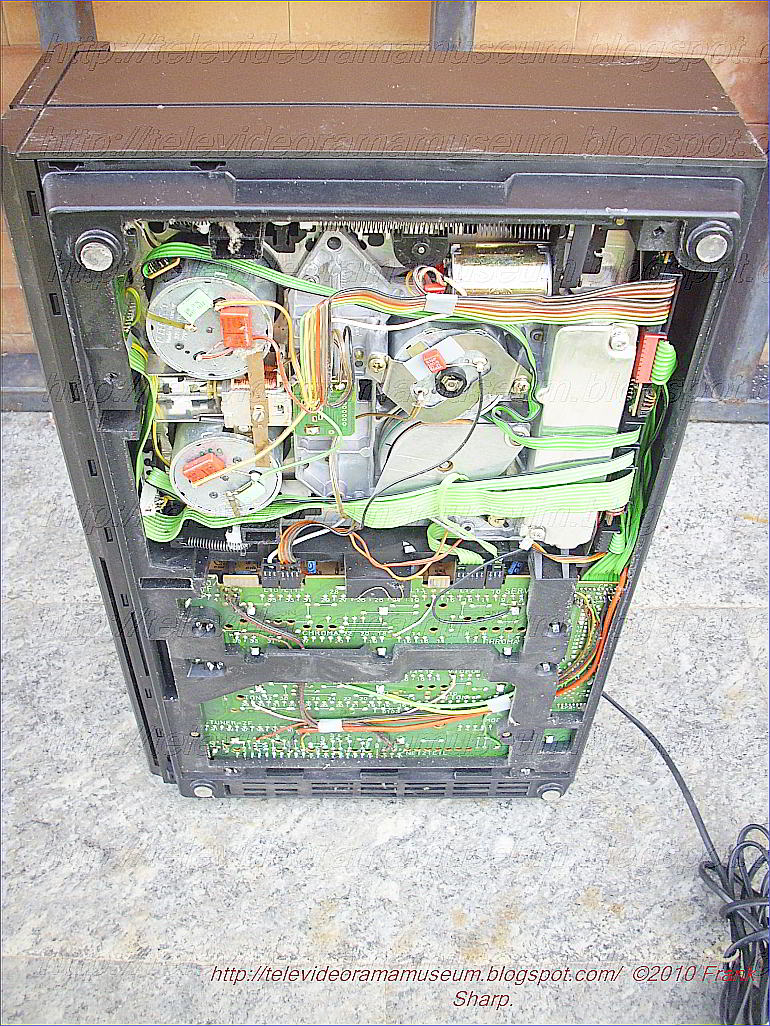
GRUNDIG VIDEO 2X4 STEREO 2200 SUPPLY TDA4600 (SIEMENS).
GRUNDIG VIDEO 2X4 STEREO 2200 Power supply Description based on TDA4601d (SIEMENS)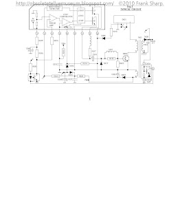 TDA4601 Operation. * The TDA4601 device is a single in line, 9 pin chip. Its predecessor was the TDA4600 device, the TDA4601 however has improved switching, better protection and cooler running. The (SIEMENS) TDA4601 power supply is a fairly standard parallel chopper switch mode type, which operates on the same basic principle as a line output stage. It is turned on and off by a square wave drive pulse, when switched on energy is stored in the chopper transformer primary winding in the form of a magnetic flux; when the chopper is turned off the magnetic flux collapses, causing a large back emf to be produced. At the secondary side of the chopper transformer this is rectified and smoothed for H.T. supply purposes. The advantage of this type of supply is that the high chopping frequency (20 to 70 KHz according to load) allows the use of relatively small H.T. smoothing capacitors making smoothing easier. Also should the chopper device go short circuit there is no H.T. output. In order to start up the TDA4601 I.C. an initial supply of 9v is required at pin 9, this voltage is sourced via R818 and D805 from the AC side of the bridge rectifier D801, also pin 5 requires a +Ve bias for the internal logic block. (On some sets pin 5 is used for standby switching). Once the power supply is up and running, the voltage on pin 9 is increased to 16v and maintained at this level by D807 and C820 acting as a half wave rectifier and smoothing circuit. PIN DESCRIPTIONS Pin 1 This is a 4v reference produced within the I.C. Pin 2 This pin detects the exact point at which energy stored in the chopper transformer collapses to zero via R824 and R825, and allows Q1 to deliver drive volts to the chopper transistor. It also opens the switch at pin 4 allowing the external capacitor C813 to charge from its external feed resistor R810. Pin 3 H.T. control/feedback via photo coupler D830. The voltage at this pin controls the on time of the chopper transistor and hence the output voltage. Normally it runs at Approximately 2v and regulates H.T. by sensing a proportion of the +4v reference at pin 1, offset by conduction of the photo coupler D830 which acts like a variable resistor. An increase in the conduction of transistor D830 and therefor a reduction of its resistance will cause a corresponding reduction of the positive voltage at Pin 3. A decrease in this voltage will result in a shorter on time for the chopper transistor and therefor a lowe
 ring of the output voltage and vice versa, oscillation frequency also varies according to load, the higher the load the lower the frequency etc. should the voltage at pin 3 exceed 2.3v an internal flip flop is triggered causing the chopper drive mark space ratio to extend to 244 (off time) to 1 (on time), the chip is now in over volts trip condition. Pin 4 At this pin a sawtooth waveform is generated which simulates chopper current, it is produced by a time constant network R810 and C813. C813 charges when the chopper is on and is discharged when the chopper is off, by an internal switch strapping pin 4 to the internal +2v reference, see Fig 2. The amplitude of the ramp is proportional to chopper drive. In an overload condition it reaches 4v amplitude at which point chopper drive is reduced to a mark-space ratio of 13 to 1, the chip is then in over current trip. The I.C. can easily withstand a short circuit on the H.T. rail and in such a case the power supply simply squegs quietly. Pin 4 is protected by internal protection components which limit the maximum voltage at this pin to 6.5v. Should a fault occur in either of the time constant components, then the chopper transistor will probably be destroyed. Pin 5 This pin can be used for remote control on/off switching of the power supply, it is normally held at about +7v and will cause the chip to enter standby mode if it falls below 2v. Pin 6 Ground. Pin 7 Chopper switch off pin. This pin clamps the chopper drive voltage to 1.6v in order to switch off the chopper. Pin 8 Chopper base current output drive pin. Pin 9 L.T. pin, approximately 9v under start-up conditions and 16v during normal running, Current consumption of the I.C. is typically 135mA. The voltage at this pin must reach 6.7v in order for the chip to start-up.

Semiconductor
circuit for supplying power to electrical equipment, comprising a
transformer having a primary winding connected, via a parallel
connection of a collector-emitter path of a transistor with a first
capacitor, to both outputs of a rectifier circuit supplied, in turn, by a
line a-c voltage; said transistor having a base controlled via a second
capacitor by an output of a control circuit acted upon, in turn by the
rectified a-c line voltage as actual value and by a reference voltage;
said transformer having a first secondary winding to which the
electrical equipment to be supplied is connected; said transformer
having a second secondary winding with one terminal thereof connected to
the emitter of said transistor and the other terminal thereof connected
to an anode of a first diode leading to said control circuit; said
transformer having a third secondary winding with one terminal thereof
connected, on the one hand, via a series connection of a third capacitor
with a first resistance, to the other terminal of said third secondary
winding and connected, on the other hand, to the emitter of said
transistor, the collector of which is connected to said primary winding;
a point between said third capacitor and said first resistance being
connected to the cathode of a second diode; said control circuit having
nine terminals including a first terminal delivering a reference voltage
and connected, via a voltage divider formed of a third and fourth
series-connected resistances, to the anode of said second diode; a
second terminal of said control circuit serving for zero-crossing
identification being connected via a fifth resistance to said cathode of
said second diode; a third terminal of said control-circuit serving as
actual value input being directly connected to a divider point of said
voltage divider forming said connection of said first terminal of said
control circuit to said anode of said second diode; a fourth terminal of
said control circuit delivering a sawtooth voltage being connected via a
sixth resistance to a terminal of said primary winding of said
transformer facing away from said transistor; a fifth terminal of said
control circuit serving as a protective input being connected, via a
seventh resistance to the cathode of said first diode and, through the
intermediary of said seventh resistance and an eighth resistance, to the
cathode of a third diode having an anode connected to an input of said
rectifier circuit; a sixth terminal of said control circuit carrying
said reference potential and being connected via a fourth capacitor to
said fourth terminal of said control circuit and via a fifth capacitor
to the anode of said second diode; a seventh terminal
of said control circuit establishing a potential for pulses controlling
said transistor being connected directly and an eighth terminal of said
control circuit effecting pulse control of the base of said transistor
being connected through the intermediary of a ninth resistance to said
first capacitor leading to the base of said transistor; and a ninth
terminal of said control circuit serving as a power supply input of said
control circuit being connected both to the cathode of said first diode
as well as via the intermediary of a sixth capacitor to a terminal of
said second secondary winding as well as to a terminal of said third
secondary winding.
Description:
The
invention relates to a blocking oscillator type switching power supply
for supplying power to electrical equipment, wherein the primary winding
of a transformer, in series with the emitter-collector path of a first
bipolar transistor, is connected to a d-c voltage obtained by
rectification of a line a-c voltage fed-in via two external supply
terminals, and a secondary winding of the transformer is provided for
supplying power to the electrical equipment, wherein, furthermore, the
first bipolar transistor has a base controlled by the output of a
control circuit which is acted upon in turn by the rectified a-c line
voltage as actual value and by a set-point transmitter, and wherein a
starting circuit for further control of the base of the first bipolar
transistor is provided.
Such a blocking oscillator switching
power supply is described in the German periodical, "Funkschau" (1975)
No. 5, pages 40 to 44. It is well known that the purpose of such a
circuit is to supply electronic equipment, for example, a television
set, with stabilized and controlled supply voltages. Essential for such
switching power supply is a power switching transistor i.e. a bipolar
transistor with high switching speed and high reverse voltage. This
transistor therefore constitutes an important component of the control
element of the control circuit. Furthermore, a high operating frequency
and a transformer intended for a high operating frequency are provided,
because generally, a thorough separation of the equipment to be supplied
from the supply naturally is desired. Such switching power supplies may
be constructed either for synchronized or externally controlled
operation or for non-synchronized or free-running operation. A blocking
converter is understood to be a switching power supply in which power is
delivered to the equipment to be supplied only if the switching
transistor establishing the connection between the primary coil of the
transformer and the rectified a-c voltage is cut off. The power
delivered by the line rectifier to the primary coil of the transformer
while the switching transistor is open, is interim-stored in the
transformer and then delivered to the consumer on the secondary side of
the transformer with the switching transistor cut off.
In the
blocking converter described in the aforementioned reference in the
literature, "Funkschau" (1975), No. 5, Pages 40 to 44, the power
switching transistor is connected in the manner defined in the
introduction to this application. In addition, a so-called starting
circuit is provided. Because several diodes are generally provided in
the overall circuit of a blocking oscillator according to the definition
provided in the introduction hereto, it is necessary, in order not to
damage these diodes, that due to the collector peak current in the case
of a short circuit, no excessive stress of these diodes and possibly
existing further sensitive circuit parts can occur.
Considering
the operation of a blocking oscillator, this means that, in the event of
a short circuit, the number of collector current pulses per unit time
must be reduced. For this purpose, a control and regulating circuit is provided.
Simultaneously, a starting circuit must bring the blocking converter
back to normal operation when the equipment is switched on, and after
disturbances, for example, in the event of a short circuit. The starting
circuit shown in the literature reference "Funkschau" on Page 42
thereof, differs to some extent already from the conventional d-c
starting circuits. It is commonly known for all heretofore known
blocking oscillator circuits, however, that a thyristor or an equivalent
circuit replacing the thyristor is essential for the operation of the
control circuit.
It is accordingly an object of the invention to
provide another starting circuit. It is a further object of the
invention to provide a possible circuit for the control circuit which is
particularly well suited for this purpose. It is yet another object of
the invention to provide such a power supply which is assured of
operation over the entire range of line voltages from 90 to 270 V a-c,
while the secondary voltages and secondary load variations between
no-load and short circuit are largely constant.
With the foregoing and other objects in view, there is
provided, in accordance with the invention, a blocking oscillator-type
switching power supply for supplying power to electrical equipment
wherein a primary winding of a transformer, in series with an
emitter-collector path of a first bipolar transistor, is connected to a
d-c voltage obtained by rectification of a line a-c voltage fed-in via
two external supply terminals, a secondary winding of the transformer
being connectible to the electrical equipment for supplying power
thereto, the first bipolar transistor having a base controlled by the
output of a control circuit acted upon, in turn, by the rectified a-c
line voltage as actual value and by a set-point transmitter, and
including a starting circuit for further control of the base of the
first bipolar transistor, including a first diode in the starting
circuit having an anode directly connected to one of the supply
terminals supplied by the a-c line voltage and a cathode connected via a
resistor to an input serving to supply power to the control circuit,
the input being directly connected to a cathode of a second diode, the
second diode having an anode connected to one terminal of another
secondary winding of the transformer, the other secondary winding having
another terminal connected to the emitter of the first bipolar
transmitter.
In
accordance with another feature of the invention, there is provided a
second bipolar transistor having the same conduction type as that of the
first bipolar transistor and connected in the starting circuit with the
base thereof connected to a cathode of a semiconductor diode, the
semiconductor diode having an anode connected to the emitter of the
first bipolar transistor, the second bipolar transistor having a
collector connected via a resistor to a cathode of the first diode in
the starting circuit, and having an emitter connected to the input
serving to supply power to the control circuit and also connected to the
cathode of the second diode which is connected to the other secondary
winding of the transformer.
In accordance with a further feature
of the invention, the base of the second bipolar transistor is connected
to a resistor and via the latter to one pole of a first capacitor, the
anode of the first diode being connected to the other pole of the first
capacitor.
In accordance with an added feature of the invention,
the input serving to supply power to the control circuit is connected
via a second capacitor to an output of a line rectifier, the output of
the line rectifier being directly connected to the emitter of the first
bipolar transistor.

In accordance with an additional feature of
the invention, the other secondary winding is connected at one end to
the emitter of the first bipolar transistor and to a pole of a third
capacitor, the third capacitor having another pole connected, on the one
hand, via a resistor, to the other end of the other secondary winding
and, on the other hand, to a cathode of a third diode, the third diode
having an anode connected via a potentiometer to an actual value input
of the control circuit and, via a fourth capacitor, to the emitter of
the first bipolar transistor.
In accordance with yet another
feature of the invention, the control circuit has a control output
connected via a fifth capacitor to the base of the first bipolar
transistor for conducting to the latter control pulses generated in the
control circuit.
In accordance with a concomitant feature of the
invention, there is provided a sixth capacitor shunting the
emitter-collector path of the first transistor.
Other features which are considered as characteristic for the invention are set forth in the appended claim.
Although
the invention is illustrated and described herein as embodied in a
blocking oscillator type switching power supply, it is nevertheless not
intended to be limited to the details shown, since various modifications
and structural changes may be made therein without departing from the
spirit of the invention and within the scope and range of equivalents of
the claims.
PHILIPS TDA373O FREQUENCY DEMODULATOR AND DROP OUT COMPENSATOR FOR VIDEO RECORDERS
GENERAL DESCRIPTION
The TDA3730 is a monolithic integrated circuit for luminance processing in the playback path of video
recorders. The device incorporates two signal channels, one for the main signal and one for the drop
out signal.
Features
FM preamplifier
Limiter in main and drop out channel
Demodulator in main and drop out channel
Drop out detector with Schmitt—trigger
Electronic switches for FM and video signal controlled by drop out detector
Linear and dynamic video de—emphasis
D.C. reference stabilizer
QUICK REFERENCE DATA
Supply voltage (pin 7 and pin 23) Vp = V7’ 23.5’ 25 typ. 10 V
Supply current (pin 7 + pin 23) Ip = I7 + I23 typ. 40 mA
FM input signal (pin 17)
(peakvto-peak value) V17.25(p_p) typ. 100 mV
Video output signal (pin 26)
(peak—to~peak value) V25.5(p_p) typ. 2 V
PACKAGE OUTLINE
28-lead DI L; plastic (SOT117).
 INTEL P8051 8-BIT CONTROL-ORIENTED MICROCONTROLLERS
8031AH18051AH18051AHP
8032N+18052N-I
8751W8751H-8
8751BW8752BI-I
High Performance HMOS Process
Internal Timers/Event Counters
2-Level interrupt Priority Structure
32 1/0 Lines (Four 8-Bit Ports)
64K External Program Memory Space
Security Feature Protects EPROM Parts
Against Software Piracy
Boolean Processor
Bit-Addressable RAM
Programmable Full Duplex Serial
Channel
111 Instructions (64 Single-Cycle)
64K External Data Memory Space
Extended Temperature Range
(–40”C to +85”C)
The
MCS@51 controllers are optimized for control applications.
Byte-processing and numerical operations on small data structures are
facilitated by a va
riety
of fast addressing modes for accessing the internal RAM. Theinstruction
set provides a convenient menu of 8-bit arithmetic instructions,
including multiply and divide instruc-tions. Extensive on-chip support
is provided for one-bit variables as a separate data type, allowing
direct bit manipulation and testing in control and logic systems that
require Boolean processing.
The 8751H is an EPROMversion of the
8051AH. It has 4 Kbytes of electrically programmable ROM which can be
erased with ultraviolet light. His fully compatible with the 8051AH but
incorporates one additional feature: a
Program Memory Security bit that can be used to protect the EPROM against unauthorized readout. The
8751H-8 is identical to the 8751H but only operates up to 8 MHz.
The 8051AHP is identical to the 8051AH with the exception of the Protection Feature. To incorporate this
Protection Feature, program verification has been disabled and external memory accesses have been limited to 4K.
The 8052AH is an enhanced version of the 8051AH. It is backwards compatible with the 8051AH and is
fabricated with HMOS IItechnology. The 8052AH enhancements are listed in the table below.
PIN DESCRIPTIONS
Vcc: Supply voltage.
Vss: Circuit ground.
Port O:Port Ois an 8-bit open drain bidirectional 1/0
port. As an output port each pin can sink 8 LS TTL
inputs.
Port Opins that have 1‘s written to them float, and in
that state can be used as high-impedance inputs.
Port Ois also the multiplexed low-order address and
data bus during accesses to external Program and
Data Memory. In this application it uses strong inter-
nal pullups when emitting 1‘s and can source and
sink 8 LS TTL inputs.
Port Oalso receives the code bytes during program-
ming of the EPROM parts, and outputs the code
bytes during program verification of the ROM and
EPROM parts. External pullups are required during
program verification.
Port 1: Port 1 is an 8-bit bidirectional 1/0 port with
internal pullups, The Port 1 output buffers can sink/
source 4 LS TTL inputs. Port 1 pins that have 1‘s
written to them are pulled high by the internal pull-
UPS,and in that state can be used as inputs. As
inputs, Port 1 pins that are externally pulled low will
source current (IILon the data sheet) because of the
internal pullups.
Port 1 also receives the low-order address bytes
during programming of the EPROM parts and during
program verification of the ROM and EPROM parts.
In the 8032AH, 8052AH and 8752BH, Port 1 pins
P1.Oand P1.1 also
serve the T2 and T2EX func-
tions, respectively.
w
Port 2 emits the high-order address byte during
fetches from external Program Memory and during
accesses to external Data Memory that use 16-bit
addresses (MOVX @DPTR). In this application it
uses strong internal pullups when emitting 1‘s. Dur-
ing accesses to external Data Memory that use 8-bit
addresses (MOVX @Ri),Port 2 emits the contents of
the P2 Special Function Register.
Port 2 also receives the high-order address bits dur-
ing programming of the EPROM parts and during
program verification of the ROM and EPROM parts.
The protection feature of the 8051AHP causes bits
P2.4 through P2.7 to be forced to O,effectively limit-
ing external Data and Code space to 4K each during
external accesses.
Port 3: Port 3 is an 8-bit bidirectional l/O port with
internal pullups. The Port 3 output buffers can sink/
source 4 LS TTL inputs. Port 3 pins that have 1‘s
written to them are pulled high by the internal pull-
UPS,and in that state can be used as inputs. As
inputs, Port 3 pins that are externally pulled low will
source current (IILon the data sheet) because of the
pullups.
Port 3 also serves the functions of various special
features of the MCS 51 Family, as listed below:
Port
Pin
P3,0
P3.1
P3.2
P3,3
P3.4
P3.5
P3.6
P3.7
Alternative Function
RXD (serial input port)
TXD (serial output port)
INTO(external interrupt O)
INT1 (external interrupt 1)
TO(Timer Oexternal input)
T1 (Timer 1 external input)
WR (external data memory write strobe)
~
(external data memory read strobe)
I
Port
Pin I
Alternative Function
I
P1.0
T2 (Timer/Counter 2 External Input)
P1.1
T2EX (Timer/Counter 2
Capture/Reload Trigger)
Port 2: Port 2 is an 8-bit bidirectional l/O port with
internal pullups. The Port 2 output buffers can sink/
source 4 LS TTL inputs. Porl 2 pins that have 1‘s
written to them are pulled high by the internal pull-
UPS,and in that state can be used as inputs. As
inputs, Port 2 pins that are externally pulled low will
source current (IILon the data sheet) because of the
internal pullups.
RST: Reset input. A high on this pin for two machine
cycles while the oscillator is running resets the de-
vice,
ALE/PROG: Address Latch Enable output pulse for
latching the low byte of the address during accesses
to external memory. This pin is also the program
pulse input (PROG) during programming of the
EPROM parts.
In normal operation ALE is emitted at a constant
rate of 1/6the oscillator frequency, and may be used
for external timing or clocking purposes. Note, how-
ever, that one ALE pulse is skipped during each ac-
cess to external Data Memory.
PSEN: Program Store Enable is the read strobe to
external Program Memory.
When the device is executing code from external
Program Memory, PSEN is activated twice each ma-
chine cycle, except that two PSEN activations are
skipped during each access to external Data Memo-
ry
~/Vpp:
External Access enable ~
must be
strapped to VSSin order to enable any MCS 51 de-
vice to fetch code from external Program memory
locations starting at OOOOHup to FFFFH. ~
must
be strapped to VCCfor internal program execution.
Note, however, that if the Security Bit in the EPROM
devices is programmed, the device will not fetch
code from any location in external Program Memory.
This pin also receives the programming supply volt-
age (VPP)during programming of the EPROM parts.
XTAL1: Input to the inverting oscillator amplifier.
XTAL2: Output from the inverting oscillator amplifi-
er,
OSCILLATOR CHARACTERISTICS
XTAL1 and XTAL2 are the input and output, respec-
tively, of an inverting amplifier which can be config-
ured for use as an on-chip oscillator, as shown in
Figure 3. Either a quartz crystal or ceramic resonator
may be used.To drive the device from an external clock source,
XTAL1 should be grounded, while XTAL2 is driven,
as shown in Figure 4. There are no requirements on
the duty cycle of the external clock signal, since the
input to the internal clocking circuitry is through a
divide-by-two flip-flop, but minimum and maximum
high and low times specified on the data sheet must
be observed.
EXPRESS Version
The Intel EXPRESSsystem offers enhancements to
the operational specifications of t
he MCS 51 family
of microcontrollers. These EXPRESS products are
designed to meet the needs of those applications
whose operating requirements exceed commercial
standards.
The EXPRESS program includes the commercial
standard temperature range with burn-in, and an ex-
tended temperature range with or without burn-in.
With the commercial standard temperature range,
operational characteristics are guaranteed over the
temperature range of O“C to + 70”C. With the ex-
tended temperature range option, operational char-
acteristics are guaranteed over a range of –40”C to
+ 85”C.
The optional burn-in is dynamic, for a minimum time
of 160 hours at 125°Cwith VCC = 5.5V * 0.25V,
following guidelines in MIL-STD-883, Method 1015.
Package types and EXPRESSversions are identified
by a one- or two-letter prefix to the part number. The
prefixes are listed in Table 1.
For the extended temperature range option, this
data sheet specifies the parameters which deviate
from their commercial temperature range limits.
ABSOLUTE MAXIMUM RATINGS*
Ambient Temperature Under Bias –40”C to + 85°C
Storage Temperature
.
–65°C to + 150°C
Voltage on EA/Vpp Pin to Vss
8751H . . . . . . . . . . . . . . . . .
–0.5V to + 21.5V
8751BH/6752BH
–0.5V tO + 13.OV
Voltage on Any Other Pinto Vss
.
–0.5V to + 7V
Power Dissipation.
. . ...
1.5W
GRUNDIG VIDEO 2X4 STEREO 2200 VIDEO2000 Reversable video cassette:

A reversible video cassette
for portable video devices is described, said cassette having two
housing halves (7, 8), mounted displaceably for changing the distance
between the winding spools. The housing halves are connected to each
other by two flat guide parts (13, 14) arranged in parallel. The two
housing halves are releasably locked by two catch hooks (17, 18)
associated with the guide parts.
VIDEO -WENDEKASSETTE PATENTANSPR·UCHE
1. Video-Wendekassette in Form eines im wesentlichen
quaderf·ormigen K·orpers mit zwei darin drehbar gelagerten Wickelspulen
f·ur das Magnetband und einer an einer schmalen L·angsfl·ache
vorgesehenen ·Offnung mit teilweise zur·uckgesetzter Geh·ausewand zur
freiliegenden Magnetbandf·uhrung, wobei die Kassette vorzugsweise aus
zwei verriegelbaren im wesentlichen geschlossenen Halbteilen besteht,
die zur Ver·anderung des Wickelspulenabstandes sowie zur Vergr·osserung
der freiliegenden Magnetbandl·ange verschiebbar gelagert sind, d a d u r
c h g e k e n n z e i c h n e t , dass die Verbindung der
verschiebbaren Kassetten
-Halbteile (7,8) durch zwei flache
F·uhrungsteile (13, 14) erfolgt, die in parallel angeordneten
F·uhrungsnuten (19, 20), die sich in den beiden ·ausseren schmalen
L·angsfl·achen (15, 16) der Geh·ausehalbteile befinden, eingelegt sind,
und die Verriegelung der beiden Halbteile durch zwei seitenversetzt den
F·uhrungsteilen zugeordnete Sperrhaken (17, 18) erfolgt.
2. Video-Wendekassette nach Anspruch 1, d a d u r c h g e
k e n n z e i c h n e t , dass die F·uhrungsteile (13, 14) aus schmalen
bandartigen Metallstreifen bestehen.
3. Video-Wendekassette nach den Anspr·uchen 1 und 2, d a
d u r c h g e k e n n z e i c h n e t , dass die F·uhrungsteile aus
antimagnetischem Federstahlband bestehen.
4. Video-Wendekassette nach Anspruch 1, d a d u r c h g e
k e n n z e i c h n e t , dass der aus Kunststoff einst·uckig
gefertigte Sperrhaken (17, 18) aus einem Hakenteil (22), einem Lagerauge
(23) und einem Verbindungssteg (24) besteht, wobei der Verbindungssteg
eine Schr·agfl·ache (27) aufweist.
5. Video-Wendekassette nach den Anspr·uchen 1 und 4, d a
d u r c h g e k e n n z e i c h n e t , dass der Sperrhaken mittels
einer Druckfeder (25) in einer die beiden Kassetten-Geh·ausehalbteile
verriegelnden Lage gehalten wird.
6. Video-Wendekassette nach einem der Anspr·uche 1 bis
5, d a d u r c h g e k e n n z e i c h n e t dass die Verriegelung der
beiden Kassetten-Halbteile durch Eintauchen wenigstens eines Stiftes (9,
10) in die Kassette aufgehoben wird, wobei der Stift auf die
Schr·agfl·ache (27) des Sperrhaken-Verbindungssteges (24) trifft und den
Haken aus einem Sperrzahn (26) hebt.
7. Video-Wendekassette nach Anspruch 6, d a d u r c h g e
k e n n z e i c h n e t , dass f·ur jeden Sperrhaken ein Stift zur
Entriegelung in die Kassette eintaucht. EMI11.1
Description:
VIDEO -WENDEKASSETTE BESCH
REIBUNG Die Erfindung betrifft eine
Video-Wendekassette in Form eines im wesentlichen quaderf·ormigen
K·orpers mit zwei darin drehbar gelagerten Wickelspulen f·ur das
Magnetband und einer an einer schmalen L·angsfl·ache vorgesehenen
·Offnung mit teilweise zur·uckgesetzter Geh·ausewand zur freiliegenden
Magnetbandf·uhrung, wobei die Kassette vorzugsweise aus zwei
verriegelbaren im wesentlichen geschlossenen Halbteilen besteht, die zur
Ver·anderung des Wickelspulenabstandes sowie zur Vergr·osserung der
freiliegenden Magnetbandl·ange verschiebbar gelagert sind.
Es sind
Magnetbandkassetten bekannt, bei denen die Bandwickelspulen mit einem
bestimmten Abstand nebeneinander in einem Kassettengeh·ause angeordnet
und die Wickelspulen von aussen ·uber ger·ateseitig angeordnete
Antriebsmittel antreibbar sind. Weiterhin sind auch Kassetten bekannt,
die eine Ver·anderung des Abstandes der Band wickelspulen erm·oglichen.
Derartige Kassetten finden insbesondere bei Videoger·aten Anwendung. Bei
Ger·aten dieser Art werden von Seiten des Benutzers, je nach
Verwendungszweck, differenzierte Anforderungen gestellt.
So wird
z. B. zwischen netzabh·angigen Heimger·aten und netzunabh·angigen, also
batteriebetriebenen, tragbaren Ger·aten unterschieden. Hierbei spielt
insbesondere das Gewicht und die Gr·osse der unterschiedlichen Ger·ate
eine erhebliche Rolle. So ist die Gr·osse des Ger·ates in erheblicher
Weise von der Gr·osse der Kassette abh·angig.
Bei einem tragbaren
Videoger·at, das beispielsweise die Bildaufzeichnung mit Hilfe einer
Videokamera erm·oglichen soll, ist eine lange Aufnahmedauer, wie sie bei
einem Heimger·at gew·unscht ist, nicht erforderlich. Dagegen spielen
jedoch das Gewicht und die Gr·osse bei einem tragbaren Videoger·at eine
erhebliche Rolle.
Aus den unterschiedlichen Anforderungen eines
Benutzers an ein Video-Heimger·at einerseits und ein tragbares
batteriebetriebenes Videoger·at andererseits ergeben sich zwangsl·aufig
abweichende Kassettengr·ossen mit unterschiedlicher Spieldauer. Der
naheliegende Wunsch, dass die kleinere, f·ur tragbare Videoger·ate
geeignete Kassette, auch auf einem f·ur gr·ossere Kassetten
eingerichtetem Heimger·at abgespielt werden soll, ist schwerlich zu
realisieren.
Es ist zwar bereits eine Kassettenkonstruktion
bekanntgeworden, bei der auch kleinere Kassetten in einem
Video-Heimger·at f·ur gr·ossere standardisierte Kassetten abgespielt
werden k·onnen, die daf·ur erforderliche Konstruktion ist jedoch recht
kompliziert und damit teuer.
So werden gem·ass diesem Stand der
Technik Zahnrad·ubersetzungen erforderlich, mit deren Hilfe der
Bandwickelabstand ausgeglichen wird.
Ein weiteres
Ausf·uhrungsbeispiel zur Anpassung einer kleineren Kassette in ein
Heimger·at, das nur f·ur eine gr·ossere Kassette geeignet ist, sieht
vor, dass die Wickel spulen in einer besonderen Lagereinrichtung
schwenkbar gelagert sind. So k·onnen die Wickel spulen mit einem
kleineren Abstand in ein kleineres Kassettengeh·ause und nach
Verschwenken in ein gr·osseres Kassettengeh·ause eingesetzt werden. Eine
Ausf·uhrung dieser Art ist ebenfalls aufwendig und erfordert vom
Benutzer ein besonderes technisches Geschick.
Eine diese Nachteile
teilweise vermeidbares Ausf·uhrungsbeispiel einer Kassette zur
Ver·anderung des Wickelspulenabstandes sieht vor, die Wickel spulen in
getrennten, zueinander verschiebbaren Geh·ausehalbteilen unterzubringen.
Die beiden Geh·ausehalbteile werden hierbei durch einen als
Hohlzylinder ausgebildeten F·uhrungsabschnitt in einer festen
Bewegungsbahn gef·uhrt.
Nachteilig ist hierbei, dass die F·uhrung
der beiden Geh·ausehalbteile keinerlei Anpassung der auseinander
gezogenen Kassetten-Geh·ausehalbteile an die Lage des im Heimger·at
ver·anderten Wickelspulenantriebs erm·oglicht.
Der Erfindung liegt
die Aufgabe zugrunde, eine relativ kleine Video-Wendekassette f·ur
tragbare Videoger·at zu schaffen, die mit geringem technischen Aufwand
auch in einem f·ur gr·ossere standardisierte Kassetten vorgesehenem
Video-Heimger·at abgespielt werden kann, wobei sich der
Wickelspulenabstand in der Kassette dem Spulenantrieb im Heimger·at
zwangsl·aufig anpasst.
Die L·osung dieser Aufgabe erfolgt erfindungsgem·ass durch die im kennzeichnenden Teil des Anspruchs 1 angegebenen Massnahmen.
Vorteilhafte Weiterbildungen ergeben sich aus den Unteranspr·uchen.
Die
Erfindung wird nachfolgend unter Bezugnahme auf die Zeichnungsfiguren
beispielsweise erl·autert. Es zeigt: Fig. 1 eine perspektivisch
dargestellte Video-Wendekassette mit abgenom mener Abdeckung und
verriegelten Kassetten-Halbteilen, Fig. 2 eine perspektivisch
dargestellte Video-Wendekassette nach Fig. 1 mit auseinandergezogenen
Kasset ten-H
albteilen, Fig. 3 eine schematische Draufsicht auf eine
Video-Wendekassette mit aus einandergezogenen Kassetten-Halb teilen nach
Fig.2, wobei ein Be reich der Kassetten-Halbteile mit aufgebrochener
Geh·ausewand ge zeichnet ist und Fig. 4 eine vergr·osserte Darstellung
eines des f·ur die Verriegelung der Kas setten-Halbteile vorgesehenen
Sperr hakens.
Die Figur 1 zeigt eine perspektivisch dargestellte
Video Wendekassette 1 - kurz Kassette genannt - mit einer von der
Kassette abgehommenen Abdeckung 2. Die Abdeckung ist f·ur den normalen
Verwendungsfall der Kassette in einem tragbaren Videoger·at stets auf
der Kassette aufgesetzt und sch·utzt das sonst freiliegende Magnetband
3. Beim Einlegen der Kassette in ein tragbares Videoger·at wird die
Abdeckung automatisch seitlich abgeklappt, und das Magnetband ist f·ur
den Zugriff von ger·ateseitig vorhandenen Ausziehstiften (nicht
gezeichnet) freiliegend. Die Kassette 1 weist die Form eines im
wesentlichen quaderf·ormigen K·orpers auf mit zwei darin drehbar
gelagerten Magnetband-Wickelspulen 4, 5. An einer schmalen L·angsfl·ache
der Kassette ist eine ·Offnung mit teilweise zur·uckgesetzter
Geh·ausewand 6 zur freiliegenden Nagnetband- f·uhrung vorgesehen.
Die
Kassette selbst besteht aus zwei im wesentlichen geschlossenen
Halbteilen 7, 8. Die einzelnen Kassetten-Halbteile 7, 8 bestehen
wiederum aus zwei fast vollst·andig geschlossenen Halbschalen, die
zusammengeschraubt oder nach einer der sonst bekannten Verbindungsformen
haltbar zusammengef·ugt sind. Beide Kassettenhalbteile 7, 8 sind
verriegelbar und k·onnen durch Eindringen von zwei Stiften 9, 10
(strichpunktiert gezeichnet) in an der Kassette vorgesehenen
F·uhrungsbohrungen 11, 12 gel·ost werden. Die Kassettenhalbteile sind
sodann auf einen vorgesehenen Abstand auseinanderzuziehen.
In der
Figur 2 ist die Kassette im auseinandergezogenen Zustand gezeichnet. Die
Verbindung der beiden verschiebbaren Kassetten-Halbteile 7, 8 erfolgt
·uber zwei flache F·uhrungsteile 13, 14. Die F·uhrungsteile sind
parallel und in geringem Abstand zu den ·ausseren schmalen
L·angsfl·achen 15, 16 der Kassetten-Halbteile angeordnet. Die
Verriegelung der Kassettenhalbteile erfolgt im geschlossenen Zustand der
Kassette ·uber die den F·uhrungsseiten zugeordneten Sperrhaken 17, 18.
Die beiden F·uhrungsbohrungen 11, 12 zur Entriegelung der Sperrhaken 17,
18 liegen im Teilungsbereich der beiden Kassetten-Halbteile 7, 8 und
bestehen somit aus den vier Bohrungsh·alften 11', 11" und 12', 12''.
Aus
der Figur 3 sind weitere Einzelheiten ·uber die Ausgestaltung der
Sperrhaken und der Lagerung der F·uhrungsteile 13, 14 in den
Kassetten-Halbteilen 7, 8 zu erkennen. Die F·uhrungsteile 13, 14 sind in
F·uhrungsnuten 19, 20, die sich im Inneren der Kassetten-Halbteile
befinden, gelagert. Um sicherzustellen, dass sich die Kassetten
Halbteile 7, 8 nicht nur in Haupterstreckungsrichtung (s. waagerechte
Pfeilangabe) der Kassette 1 gegeneinander verschieben lassen, sondern
auch in begrenzter Weise senkrecht hierzu (s. senkrechte Pfeilangabe)
ausweichen k·onnen, sind die F·uhrungsteile 13, 14 aus schmalem
Federbandstahl gefertigt.
Die Bandwickelspulen 4, 5 in der
ausgezogenen Kassette k·onnen sich somit der Lage der im Heimger·at
befindlichen und gegen·uber dem tragbaren Videoger·at unterschiedlichen
Antriebselementen voll anpassen. Zur Begrenzung der Auszugsl·ange der
Kassette weisen die F·uhrungsteile 13, 14 Begrenzungsnasen 21 auf.
Die Figur 4 zeigt einen vergr·ossert gezeichneten Ausschnitt des Sperrhakens aus einem Kassetten-Halbteil.
Der
Sperrhaken 18 besteht aus einem Hakenteil 22, einem Lagerauge 23 und
einem Verbindungssteg 24. Eine Druckfeder 25, die auf dem
Verbindungssteg des Sperrhakens aufgesetzt ist und sich im Geh·ause des
Kassetten-Halbteils abst·utzt, sorgt f·ur den n·otigen
Verriegelungsdruck bei zusammengeschobenen Kassetten-Halbteilen. Im
verriegelten Zustand beider Halbteile 7, 8 liegt das Sperr
haken-Hakenteil 22 des einen Halbteils in einertrSperr- zahn 26 des
anderen Halbteils. ·Uber eine Schr·agfl·ache 27, die sich am
Sperrhaken-Verbindungssteg befindet, kann ·uber das Auftreffen eines in
die Kassette eintauchenden Stiftes 9, 10 die Verriegelung des
Sperrhakens aufgehoben werden. Das Hakenteil 22 des Sperrhakens weist in
bekannter Weise eine Anlaufschr·age auf ·Uber einen Lagerstift ist der
Sperrhaken 18 im Kassetten-Halbteil drehbar gelagert.
GRUNDIG VIDEO 2X4 STEREO 2200 Arrangement for the recording and reproduction of wide frequency band video signal:
Method of recording and reproduction of wide frequency band video
signals onto or from a magnetizable recording carrier, carried out by
the following means: means for separating

of the video frequency signals
into first and second signals of lower and upper frequency range
respectively, for converting said second signal into a third signal the
frequency range of which equaling that of said first signal, for
frequency modulating a carrier wave frequency by said first and third
signals and for recording the frequency modulated signals by means of a
twin head, for reproducing the recorded signals by means of a twin head
and for amplifying, limiting and demodulating the recorded signals and
reconverting the third signal into its original frequency range and
combining the so reconverted third signal and said first signal.
1. An apparatus for
the recording and reproducing of wide frequency band color video signals
onto or from two adjacent tracks of a magnetizable recording carrier,
whereat the color video signal to be recorded is separated into a lower
and upper frequency range, said lower frequency range frequency
modulating a carrier wave, said apparatus further comprising:
a. means for converting said upper frequency range into said lower frequency range;
b. means for frequency modulating said carrier wave by said converted upper frequency range;
c. twin head means for simultaneously recording both said frequency modulated signals; and,
d. means for reproducing the recorded signals encoding the twin head,
means for amplifying, limiting and demodulating the recorded signals and
for reconverting the converted upper frequency range into its original
frequency range and for combining the reconverted signal and the lower
frequency range signal.
2. The apparatus in accordance wit

h claim 1 wherein the
mixing frequency used for the converting and reconverting of the upper
frequency range is an integral multiple of the line frequency.
3. The apparatus in accordance with claim 1 wherein the
individual recording heads of the twin head have azimuth-angles which
are different from zero and are equal in value but oppositely inclined.
Description:
BACKGROUND OF THE INVENTION
In view of the
limited band width of the frequency band of simple tape video recording
and reproducing apparatuses for home use a color television signal can
be recorded only with losses in quality and after a considerable
transformation of the original video signals.
For example, in a
widely used European system of recording and reproduction, the
brightness and chrominance signals are separated from each other. A
carrier frequency located at about 4 MHz is frequency-modulated with the
brightness signal, which is limited to 2.7 MHz. The chrominance signal
is moved out of its original frequency position into a new frequency
range, which is located lower than that of the lower side bands of the
frequency-modulated brightness signals. Thereafter the
frequency-converted color signals are added and recorded.
Japanese
systems, which also were developed especiall

y for home use, use
essentially the same principle. Both systems suffer from serious
disadvantages. The procedure is intricate and includes many
possibilities for error, if the luminance and chrominance signals are
separated, processed in a different manner and then put together again.
The frequency band width of the brightness signal must be narrowed.
Since a portion of the tape recorded information is contained in the
amplitude, the advantage of frequency modulation largely is lost. The
track width cannot be reduced below a certain minimum figure and the
color information is recorded at a relatively large wave length. The
danger of cross-talk and especially cross-color disturbances between
neighboring tracks exists just where it is most conspicuous. This can be
avoided by the provision of guard bands between the tracks, but because
the guard bands do not carry any information a large amount of tape is
needed.
If guard bands between adjacent tracks are omitted,
adjacent tracks are recorded and read at different azimuth angles, and
the polarity of the color information is changed from line to line,
which requires not only additional electronics but requires a radically
different lay-out of the whole electronic circuit, depending upon
whether the apparatus is to be used for NTSC, PAL or SECAM.
SUMMARY OF THE INVENTION

It
is an object of the present invention to provide a recording and
reproducing arrangement for wide frequency band video signals onto or
from a magnetizable carrier, which avoids the above described faults and
which especially permits the recording of the full video frequency band
with small and inexpensive apparatuses and without additional tape
consumption at full utilization of the advantages of frequency
modulation. The color television system (NTSC, PAL or SECAM) does not
influence the recording, so that the same apparatus can be used for all
systems, except of course, for different power supply frequencies.
The
inventive combination is new and brings out a surprising result. For
example, the frequency transformation of a portion of the color
television signal is known. U.S. Pat. No. 3,234,323 discloses the method
of modulation onto a carrier frequency for the brightness and the color
and to record each in parallel tracks. German Pat. No. 1,935,109
discloses means to record on adjacent tracks without leaving space in
between, but with different azimuth angles. In comparison, none of the
known arrangements permits recording of the full color television signal
frequenc
y band with small and inexpensive apparatus independently of
the color transmission system and with full utilization of the
advantages of frequency modulation and without additional tape
consumption and loss of quality.
BRIEF DESCRIPTION OF THE DRAWINGS
FIGS. 1 and 2 taken together provide a diagrammatic showing of the subject invention.
DESCRIPTION OF THE PREFERRED EMBODIMENT
An
embodiment of the in

vention is shown in the FIGS. in which for example
the mean track spacing amounts to 187 μm, the width of a track itself is
130 μm, the frequency modulation deviation ranges from 3.1 MHz to 4.5
MHz, and at this condition video signals up to 2.7 MHz with 10 dB loss
can be recorded. If now, according to the invention, the mean track
spacing is divided into two tracks each of 93.5 μm track width lying
parallel and adjacent to one another without interspace, and if, from
the signal which is introduced at connection 1, a lower frequency range
extending up to 2.7 MHz is separated by a low-pass filter 2, then this
lower frequency range may be frequency modulated in a modulator 3 and
after appropriate amplification in an amplifier 4 be recorded by a
magnetic transducer head 5, just as well as in the aforementioned
original state. Simultaneously, the line synchron impulses are separated
at 6 and an upper frequency range of the color television signal from
2.7 MHz to 5.5 MHz is made available over the high-pass filter 7. The
frequency of the output voltage of a voltage controlled oscillator (VCO)
8 with a nominal frequency of about 2.6 MHz is divided in a divider 9
by, for example, 166 and compared with the line synchron impulses in a
phase comparator 10; the difference signal synchronizes the oscillator 8
to a frequency which is an integral multiple of the line frequency. The
mixing of the output voltages of the
oscillator 8 and of the high-pass
filter 7 in a mixing unit 11 and the limiting by a low-pass filter 12,
whose cut-off frequency may lie a little higher than those of 2, effects
a transposition of the upper video frequencies into the same frequency
range as is behind the low-pass filter 2; the signals applied to the
frequency modulators 3 and 13, may also be treated in the same manner,
especially with respect to a possible pre-emphasis and the modulation
itself; the last is indicated by a common carrier wave oscillator 16.
The signal, which is frequency modulated in 13, is applied by way of an
amplifier 14 to a further magnetic head 15, which is preferably combined
with the magnetic head 5 to form a twin head, recording simultaneously
with head 5 parallel tracks without any interspace. Technologically, the
amplifiers 4 and 14 and the heads 5 and 15 are of equal design; as
later will be explained, only the azimuth angles of the gaps of heads 5
and 15 differ from each other.
In the play-back apparatus
according to
FIG. 2, the amplifiers 17, the limiters 18 and the
demodulators 19, which are following the heads 5 and 15, are once more
built wholly alike; the blocks 6, 8, 9, 10 and 11 are the same for
recording, according to FIG. 1 and for reproducing, according to FIG. 2.
The output voltage of the mixing unit 11 is taken through a band-pass
filter 20, which filters out the upper side band of the mixing product,
and transfers it to an adder stage 21, which also receives the
demodulated signals read by head 5. If necessary, there may be inserted
frequency-response corrections at suitable places, deemphasis on offset
compensators, and this in both channels.
The synchronization to
the line frequency of the mixing frequency of the oscillator 8, which is
required for the frequency shift, proves to be especially advantageous,
because by this, large time basis deviations are compensated for. The
upper cut-off frequency of the demodulated signal, which head 5 picks
up, is thus shifted exactly as much as the lower cut-off frequency
behind the band-pass filter 2
0, so that the crossover positions between
the two ranges of video frequencies are not changed relative to each
other.
As a result, compared with the original shape, the upper
useful video frequency can be doubled without loss of playing time or
quality, and this, without having to extract the chrominance signal out
of the color television signal and without having information carried by
the amplitude of the magnetization, which exists at the tape. For this
latter reason, the width of the tracks may be further decreased, and in
this way, the playing time can be again increased.
Compared with
the aforementioned Japanese system, it is true that this system also
uses the advantage of abutting tracks. But instead of this, another
advantage is obtained in that the very complicated and from television
system to television system very different processing of the color
signal is avoided; also the disadvantage of a chrominance sub-carrier
transposed into a low frequency range, namely the therewith associated
danger of cross-talk from track to track is very greatly reduced. For
example: the converted chrominance sub-carrier frequency is normally of
the order of 600 kHz. If there is a track width without interspace of 55
μm, a head to tape speed of 6000 mm/s and an azimuth-angle of 8° Which
is contrarotating from track to track (which means 16° effective for
each head), and the scanning head deviates by 9% of the track width out
of its track, the cross-talk results in a signal to noise ratio o
f 20.4
dB. This ratio is too small and must therefore be further diminished by
complicated and expensive electronic means with the help of comb
filters. According to the invention all recorded frequencies are located
at 4 MHz; under otherwise equal circumstances the cross-talk ratio now
amounts to 45 dB, which requires no additional distortion suppressing
means.
The invention is not limited to the specific oblique track
recording, but can also be used at the transverse track, or the
longitudinal track methods using rotating magnetic heads. The advantages
derived from the invention is independent of the shape (form) of the
record carrier and of the track.
GRUNDIG VIDEO 2X4 STEREO 2200 Method and device for tracking video signals on a magnetic VIDEO2000 SYSTEM tape by detecting phase jumps:
A method and device for maintaining an exact track when playing back
video ignals, which are recorded on a magnetic tape in oblique parallel
tracks with different azimuth angles.
1. A device for
adjusting the exact position of the track when replaying video signals
which are recorded in oblique parallel tracks on a magnetic tape, said
oblique tracks being al
ternately recorded and replayed by two rotating
heads, the gaps of which have opposite equal azimuth angles causing
phase jumps of the line frequency of the scanned video signal during
track changes in case of mistracking, said device including means for
detecting said phase jumps, and means for applying said phase jumps to
said rotating heads to readjust the rotating video heads to the exact
track position by control of the tape speed.
2. A device in accordance with claim 1 further
comprising means for measuring the phase jumps of the line frequency for
changes from an even numbered to an odd numbered track and for changes
from an odd numbered to an even numbered track.
3. A device in accordance with claim 2 in which the
phase jumps of the line frequency of the video signal with respect to a
reference frequency during subsequent track changes are detected by
different sample and hold circuits, the outputs of said sample and hold
circuits being fed to the input of a differential amplifier to form an
error signal, said error signal controlling the tape speed so as to
minimize said error signal.
4. A device according to claim 2 further comprising a
phase locked loop to produce the reference frequency synchronized to the
line frequency of the scanned video signal, said phase locked loop
containing a phase comparator, a voltage controlled oscillator and a low
pass filter therebetween, said low pass filter causing the control time
constant of the voltage controlled oscillator to equal at least the
scanning time of one track.
5. A device according to claim 3 in which the separated
line pulses from the scanned video signal are fed through gate circuits
to the sample and hold circuits, and which are alternately opened for
about two line intervals by pulses which are derived from the position
signals of the head wheel each time a video head starts to scan a new
track.
6. A device according to claim 5 in which the error
signal of the differential amplifier is added to or subtracted from the
rectified voltage of the tacho generator of the tape feed motor and in
which by comparing the sum or difference, respectively, with a given
reference voltage the rotation of the tape feed motor is controlled so
as to minimize the error voltage produced by the differential amplifier.
7. A device according to claim 6 in which a low pass
filter is provided at the output of the differential amplifier.
Description:
BACKGROUND OF THE INVENTION
When recording video
signals in o
blique parallel tracks cross-talking from track to track
can be kept to a minimum if the tracks are separated by guard bands.
However, such guard bands are a poor way of using the available
recording face.
Another possibility for minimizing cross-talk is
to record with azimuth angles which differ from track to track. In such a
case the guard bands can be eliminated. However, in such a system the
requirement for exactly scanning the recorded track is increased.
Methods
and devices for an automatical tracking during play-back of video
signals in oblique tracks are known, but were never attractive for
incorporation into devices for home use. For example it has been
suggested to use the time difference which occurs simultaneously with a
migration as a measure of the lateral migration of the replay head from
the magnetic track. This method can be accomplished by very simple
circuitry but poses high demands with respect to the precision and the
timely constancy of such circuits, because very small and continuously
changing time intervals must be measured.
SUMMARY OF THE INVENTION
The
subject invention provides a device and a method wherein an exact
tracking is made

possible without expensive equipment and without
significant requirements for precision, durability and constancy of the
circuit elements.
The invention is related to video tape
recorders where the video signals are recorded in oblique parallel
tracks which are alternately recorded and replayed by two rotating video
heads with gaps having opposite azimuth angles. The migration of the
video heads from the exact track position is determined by the phase
jump which occurs during track change.
The invention is based on
the realization that the sudden change of a magnitude is easier to
measure than a continuous change.
BRIEF DESCRIPTION OF THE FIGURES
FIG. 1 is a diagrammatic representation of two oblique tracks with the tape scanning and tape feeding directions indicated;
FIG. 2 is a schematic diagram utilizing the subject invention; and
FIG. 3 is a schematic diagram illustrating a further embodiment of the invention.
DESCRIPTION OF A PREFERRED EMBODIMENT
FIG.
1 sho

ws two oblique tracks 1 and 2. For track 1 the recording and
replay gap of the magnet head is turned from the vertical position
counterclockwise through angle α and for track 2 in a clockwise
direction through an equal angle α . If during replay the heads are
displaced from the nominal position 3, 4 into position 3', 4' by an
amount h perpendicular to the track direction, an additional phase
change occurs in addition to the reduction of the signal to noise ratio.
With the scanning and tape feeding directions and with the azimuth
angles of FIG. 1 head 3' scans the video signal by an amount (h) (tan α)
earlier and head 4' by an amount (h) (tan α) later than at nominal
position. Therefore, during the change from track 1 to track 2 a sudden
phase jump takes place corresponding to (2) (h) (tan α) rearwardly and
from track 2 to track 1 forwardly. However, if heads 3 and 4 are not
migrating upwardly as shown in FIG. 1 but rather downwardly, the sudden
phase jump takes place with the magnitude (2) (h) (tan α) forwardly and
from track 2 to track 1 rearwardly. Therefore, the magnitude of the
phase jump is a measure of the magnitude of migration of the video heads
from the track, while the sign of the phase jump determines the
direction of migration.
In the invention the phase jump is
measured at the line frequency with respect to a reference oscillation
which is synchronized to the line frequency but which cannot follow
sudden phase jumps or rapid frequency changes. For this purpose a
voltage controlled oscillator 8 is provided as can be seen in FIG. 2
which oscillates at about double the line frequency and which is
synchroniz
ed by means of phase comparator 6 and low pass filter 7 to the
line pulses fed at 5 and separated from the scanned video signal. The
double line frequency is chosen because of the frequency of the
equalizing pulses of the vertical signal, and the low pass filter 7
prevents oscillator 8 from following immediately the occuring phase
jumps.
Simultaneously, the scanned line pulses are fed to gate
circuits 12 and 13 which open for a short time for about two line
durations after each second head change. The necessary opening pulses
are fed at 14 and 15 and are derived from the position pulse of the head
wheel, so that gate 12 opens when changing from track 1 to track 2, for
example, while gate 13 opens when changing from track 2 to the next
track.
It is useful to transform the output voltage of oscillator
8 into a trapezoidal wave by pulse former 9 the output of which is fed
as a reference to the sample and hold circuits 10 and 16 or 11, 16,
respectively. The output signals of 10 and 11 are coupled to the input
of differential amplifier 17.
The error signal which is generated
at t
he output of the differential amplifier 17 may be used for making
an exact track adjustment for the video heads. For example, the error
signal may influence the recovery time of a monostable multivibrator 18
to which the reference pulses for the servo control circuit 20 of the
tape transport motor are fed at 19. Another possibility exists in the
immediate adjustment of the rotating video heads in axial direction by
means of piezoceramic elements which are excited by the error signal of
differential amplifier 17.
Since the maintaining of the track and
the transport speed for the tape are unmistakeably correlated in
accordance with the invention the reference pulses which are fed at 19
may be omitted in accordance with a further embodiment of the invention.
In other words, the usual synchronous track is not necessary.
In
accordance with FIG. 3, the servo control circuit of band feeding motor
21 includes tacho generator 22 which is coupled with motor 21, and the
output voltage of the generator after being rectified at 23 is coupled
to the input of a differential amplifier 24. The other input of
differential amplifier 24 is coupled to a reference voltage 25. This
control loop controls the tape feeding speed approximately to the
nominal value, while the output voltage of the differential amplifier 17
which is fed into the summing element 26 provides the exact adjustment
of the tape speed with respect to the exact track adjustment.
The
additional low pass filter 27, 28 is only necessary for the start of
the tape movement and elimates the big alternating phase jumps generated
during the acceleration of the magnetic tape.
GRUNDIG VIDEO 2X4 STEREO 2200 Method for dynamic track adjustment in SYSTEM VIDEO2000 video recorders:.
1. Method for dynamic equidistant track adjustment in magnetic
helical-scan video recording with the aid of rotating magnetic video
heads which are adjustable by a servosystem perpendicularly to the
direction of movement, the servosystem being controlled by a control
signal (burst) of a particular frequency keyed in each case at the
beginning of the track and the area of reproduction of a new track being
located immediately adjacent to the area of recording of the preceding
track, characterized in that the order of recording and reproduction for
the control signal (burst) keyed in arbitrary length, relative to the
scanning movement of the magnetic video head, takes place alternatingly
from track to track and, relative to the beginning of the track, offset
in time and geometry from track to track.
VERFAHREN ZUR DYNAMISCHEN SPUREINSTELLUNG
BEI VIDEORECORDERN PATENTANSPR·UCHE
1. Verfahren zur dynamischen ·aquidistanten
Spureinstellung bei der magnetischen Schr·agspur-Videoaufzeichnung mit
Hilfe von rotierenden Video-Magnetk·opfen, die senkrecht zur
Bewegungsrichtung durch ein Servosystem verstellbar sind, wobei die
Ansteuerung des
Servosystems durch ein jeweils am Spuranfang
eingetastetes Steuersignal (Burst) bestimmter Frequenz erfolgt, d a d u r
c h g e k e n n z e i c h n e t dass die Reihenfolge der Aufzeichnung
und Wiedergabe f·ur das in beliebiger L·ange eingetastete Steuersignal
(Burst) bezogen auf die Abtastbewegung des Video Magnetkopfes von Spur
zu Spur alternierend und bezogen auf den Spuranfang von Spur zu Spur
zeitlich und geometrisch versetzt erfolgt, derart, dass der
Wiedergabebereich einer neuen Spur dem Aufzeichnungsbereich der
vorangegangenen Spur unmittelbar benachbart ist.
2. Verfahren nach Anspruch 1, d a d u r c h g e k e n n z
e i c h n e t , dass in jeder zweiten Spur zwischen dem Aufzeichnungs-
und Wiedergabebereich des Steuersignals (Burst) eine L·ucke mit der
L·ange des doppelten Spurversatzes eingef·ugt ist.
3. Verfahren nach Anspruch 1, d a d u r c h g e k e n n z
e i c h n e t , dass in jeder zweiten Spur die Summe der zeitlichen und
geometrischen L·ange des Aufzeichnungs- und Wiedergabebereichs f·ur das
Steuersignal (Burst) um den doppelten Spurversatz vergr·ossert wird.
Description:
VERFAHREN ZUR DYNAZIISCHEN SPUREINSTELLUNG BEI VI DEORECO
RDERN BESCHREIBUNG Die Erfindung betrifft ein Verfahren, mit dem bei der
magnetischen Videoauf zeichnung die ohne Zwischenraum
aneinandergrenzenden, winkelentkoppelten Schr·ag spuren auf konstanten
Abstand gebracht werden k·onnen.
Die Anwendung des Verfahrens
setzt voraus, dass die aufzeichnenden bzw. wiedergebenden rotierenden
Video Magnetk·opfe senkrecht zu ihrer Abtastrichtung gesteuert bewegbar
sind. Die gesteuerte Bewegbarkeit, wie sie z.B. beim System ~Video 2000"
angewendet wird, dient prim·ar der Spurfindung bei der Wiedergabe.
Hierzu werden zus·atzlich zum Luminanz- und Chrominanzsignal
beispielsweise vier Hilfsfrequenzen aufgezeichnet, die unterhalb des
Chrominanzsignals und Luminanzsignals liegen und die bei der Wiedergabe
in einer Servoschaltung derart verarbeitet werden, dass der
Wiedergabekopf immer so eingestellt wird, dass er auf der gewunschten
Magnetspur l·auft.
Einzelheiten ·uber dieses Verfahren sind
beispielsweise aus WGrundig Technische lnforma- ton
en", Heft 3/198Q,
Seite 111 ff. und "Grundig Technische Infonmationen", Heft 3/1981, Seite
105 ff. zu entnehmen.
Die M·oglichkeit der Steuerung der
Magnetk·opfe senkrecht zur Spurrichtung wird ausser zur Spurfindung bei
der Wiedergabe aber auch bei der Aufnahme dazu benutzt, um die
aufeinanderfolgenden Spuren ·aquidistant zu schreiben.
Hierzu wird
ein Schwingungszug, auch Burst genannt, am jeweiligen Spuranfang mit
einer weiteren Hilfsfrequenz aufgezeichnet. Unmittelbar nach der
Aufzeichnung des Burstsignals, dessen Dauer nach dem Stand der Technik
dem von Spur zu Spur entstehenden Spurversatz entspricht, wird der
rotierende Magnetkopf auf Wiedergabe umgeschaltet und tastet das
Burstsignal der vorhergehenden Spur ab. Die Amplitude des da
bei
gewonnenen Signals ist ein Mass f·ur den Spurabstand und kann zur
Einstellung des rotierenden Magnetkopfes am Spuranfang benutzt werden,
derart, dass die Spurabst·ande konstant sind.
Die Bezugsgr·osse
bei diesem Regelvorgang wird beim Stand der Technik dadurch gewonnen,
dass einer der beiden rotierenden Video-Magnetk·opfe auf dem Kopf rad
hinsichtlich seiner Einstellung senkrecht zur Abtasteinrichtung eine
feste Vorgabe erh·alt und nur der zweite Kopf so geregelt wird, dass
·aquidistante Spuren entstehen. Es ist prinzipiell aber auch m·oglich,
jeweils bei Beginn einer Aufzeichnung die erste Spur mit fest
eingestelltem rotierenden Video-Magnetkopf zu schreiben und
anschliessend beide Video-Magnetk·opfe fortlaufend auf konstanten
Spurabstand einzuregeln.
F·ur die exakte Spureinstellung darf
dabei das Burstsignal nicht zu kurz sein, da mit der nachfolgenden
Auswerteschaltung und auch mit der Umschaltung Aufnahme/ Wiedergabe
Einschwingvorg·ange mit bestimmter Zeitdauer verbunden sind.
Wird
die Aufzeichnung des Burstsignals nach de
m Stand der Technik
entsprechend der Dauer des Spurversatzes gew·ahlt, dann liegen die
Aufzeichnungsabschnitte in benachbarten Spuren geometrisch
treppenf·ormig zueinander wie aus Figur 1 ersichtlich. Der rotierende
Magnetkopf kann dann sofort nach der Aufzeichnungsperiode f·ur den Burst
auf Wiedergabe umgeschaltet und nach Massgabe des aus der
vorhergehenden Spur abgetasteten Burstsignals auf exakten Spurabstand
eingestellt werden.
Bei geringer Spurbreite bzw.
Bandgeschwindigkeit und entsprechend geringer Spurneigung kann der
Spurversatz auf sehr kleine Werte absinken. Entsprechend den oben
geschilderten Zusammenh·angen wird dann nach dem Stand der Technik die
Dauer des Burstsignals ebenfalls auf einen geringen Wert reduziert. Es
besteht dann die Gefahr, dass dieses zeitlich verk·urzte Burstsignal mit
R·ucksicht auf die mit der Kopfregelung verbundenen Einschwing- und
Urnschaltvorg·ange f·ur eine st·orsichere Regelung nicht mehr ausreicht.
Man
k·onnte daran denken, das Burstsignal zeitlich ·uber den Spur versatz
hinaus zu verl·angern, um wieder eine sichere Auswertung zu erreichen.
Dann aber wandert die geometrische und zeitliche Position des
Burstsignals von Spur zu Spur immer weiter auf der Aufzeichnungsspur
voran und w·urde schliesslich den Videosignal-Austastbereich verlassen
bzw. in den Bildsignalbereich gelangen. Dies ist zur Vermeidung von
St·orungen unzul·assig.
Ausserdem l·asst sich bei zunehmender
Entfernung der Burstaufzeichnung vom Spuranfang das gew·unschte Ziel der
Spureinstellung im Sinne eines konstanten Spurabstandes am Spuranfang
nicht mehr befriedigend erreichen.
Aufgabe der Erfindung ist es,
bei der magnetischen Video aufzeichnung in Schr·agspuren auch bei
geringem Versatz von Spur zu Spur ein Burstsignal f·ur die Einstellung
des Spurabstandes aufzuzeichnen und wiederzugeben, das in seiner
zeitlichen Ausdehnung so gew·ahl
t werden kann, dass eine sichere
Auswertung mit Hilfe der Regeleinrichtung f·ur die Verstellung des
Magnetkopfes senkrecht zur Abtastrichtung im Sinne der Erreichung
·aquidistanter Spuren m·oglich ist.
Die erfindungsgem·asse L·osung
dieser Aufgabe ist aus Figur 2 ersichtlich. Wird n·amlich die zeitliche
Folge der Aufzeichnung und Wiedergabe des Burstsignals von Spur zu Spur
alternierend gew·ahlt, dann kann das Burstsignal zeitlich ausgedehnt
werden, ohne dass die unerw·unschte Erscheinung der Wanderung innerhalb
der Spur in Abtastrichtung auftritt. Im dargestellten Beispiel nach
Figur 2 ist in der ersten Spur die geometrische und zeitliche L·ange der
Burstaufzeichnung beliebig gew·ahlt. In der folgenden Spur wird nun die
Burstaufzeichnung bezogen auf den Spuranfang um die Burstl·ange
zuz·uglich des Spurversatzes verschoben und der Lesevorgang vor den
Schreibvorgang gelegt. Damit wird der zeitlich verl·angerte Burst
vollst·andig ausgewertet und ein neuer Burst mit der gleichen L·ange
aufgezeichnet.
In der dritten Spur schliesslich setzt die
Burstaufzeichnung bezogen auf den Spuranfang wieder so ein wie in der
ersten Spur, w·ahrend der Lesevorgang gegen·uber der Aufzeichnung um die
Burstl·ange zuz·uglich des doppelten Spurversatzes verschoben ist.
Durch Vertauschung der Reihenfolge von Schreiben und Lesen sowie durch
Einf·ugen einer L·ucke zwischen Schreiben und Lesen in jeder zweiten
Spur um die Dauer des doppelten Spurversatzes wird also sichergestellt,
dass bei verl·angerter Burstdauer das Burstsignal in voller L·ange
gelesen werden kann und trotzdem der Schreib- und Lesevorgang am
Spuranfang verbleibt, wie es f·ur die wirkungsvolle und st·orsichere
Regelung des Spurabstandes n·otig ist.
Ausserdem wird durch die
erfindungsgem·asse Auf zeichnungs- Wiedergabe-Geometrie f·ur das
Steuersignal (Burst) erreicht, dass jedem der beiden Magnetk·opfe ein
konstanter zeitlicher Ablauf f·ur Aufzeichnung und Wie
dergabe zugeordnet
ist. Mit anderen Worten, der erste Videokopf (ungeradzahlige Spuren)
zeichnet in festem Abstand oder zeitlicher Dauer vom Spuranfang auf,
dann folgt eine L·ucke entsprechend dem doppelten Spurversatz, danach
der Wiedergabebereich f·ur das Steuersignal (Burst).
Der zweite
Videokopf (geradzahlige Spuren) gibt in festem Abstand oder zeitlicher
Dauer vom Spuranfang wieder und zeichnet ohne l·ucke anschliessend auf.
Zum
besseren Verst·andnis des Verfahrens sei noch angemerkt, dass die
Wiedergabe des Steuersignals (Burst) aus der vorhergehenden Spur trotz
Winkelentkopplung auch dann noch m·oglich ist, wenn der Video-Magnetkopf
die vorhergehende Spur nicht mehr unmittelbar trifft.
Dies
erkl·art sich daraus, dass die Frequenz des Steuersignals bezogen auf
das Video signal verh·altnism·assig niedrig gew·ahlt wird, so dass die
Winkelentkopplung unwirksam wird und das Streufeld ·uber die Spurbreite
hinaus wirkt.
DEVICE FOR ROTATING ANNULAR TRANSFORMERS IN A VIDEO SET:
1. Arrangement of rotating toroidal transformers (10, 11) for the
inductive transmission of high-frequency oscillations in a video
recording and playback machine with at least two signal recording and
playback heads (5, 6), which are preferably arranged offset by 180
degrees on a rotating head wheel (2) in a head drum, the transformers
each having one rotating (10', 11') toroidal part and one fixed (10",
11") toroidal part, each signal head (5, 6) being assigned the rotating
part of a transformer in a certain way, and the transformers (10, 11)
being arranged axially one above the other, characterized in that the
transformers (10, 11) have different ring sizes such that they do not
radially overlap.
ANORDNUNG VON ROTIERENDEN RINGF·ORMIGEN
TRANSFORMATOREN IN EINEM VIDEOGER·AT PATENTANSPR·UCHE
1. Anordnung von rotierenden ringf·ormigen
Transformatoren zur induktiven ·Ubertragung hochfrequente
r Schwingungen
in einem Video-Auf zeichnungs- und -Wiedergabeger·at mit wenigstens zwei
Signal-Aufzeichnungs- und Wiedergabek·opfen, die vorzugsweise um 180
versetzt auf einem rotierenden Kopfrad in einer Kopftrommel angeordnet
sind, und jedem Signalkopf der rotierende Teil eines Transformators in
bestimmter Weise zugeordnet ist, d a d u r c h g e k e n n z e i c h n e
t , dass ein Transformator (10) mit rotierendem und feststehendem
ringf·ormigem Teil des ersten Signalkopfes (5) gegen·uber dem anderen
rotierenden Transformator (11) des zweiten Signalkopf es (6) axial
verschoben und durch verschiedene Ringgr·ossen radial und axial nicht
·uber schneidend in der Kopftrommel (1) angeordnet ist.
2. Anordnung nach Anspruch 1, d a d u r c h g e k e n n z
e i c h n e t , dass das Kopfrad (2) einen hochgezogenen Flansch (13)
aufweist, auf den ein rotierender Trafoteil (11) aufgesetzt ist,
w·ahrend der andere rotierende Trafoteil mit der geringeren Ringgr·osse
(10') auf der inneren Planseite des Kopfrades (14) angeordnet ist, und
die H·ohe des Flansches wenigstens der gesamten Querschnittsh·ohe eines
Transformators entspricht.
3. Anordnung nach Anspruch 2, d a d u r c g e k e n n z e
i c h n e t , dass die H·ohe des Flansches des Kopfrades der halben
Querschnittsh·ohe des kompletten Transformators entspricht.
Description:
ANORDNUNG VON ROTIERENDEN RINGF·ORMIGEN TRANSFOXMATQREN IN
EINEM VIDEOGER·AT BESCHREIBUNG Die Erfindung betrifft eine Anordnung von
rotierenden ringf·ormigen Transformatoren zur induktiven Ubertragung
hochfrequenter Schwingungen in einem Video-Aufzeichnungs- und
Wiedergabeger·at mit wenigstens zwei Signal-Aufzeichnungs- und
Wiedergabek·opfen, die vorzugsweise um 1800 versetzt auf einem
rotierenden Kopfrad in einer Kopftrommel angeordnet sind, und jedem
Signalkopf der rotierende Teil eines Transformators in bestimmter Weise
zugeordnet ist.
Bei den meisten bekannten magnetischen
Bild-Aufzeichnungs- und Wiedergabeger·aten mit bandf·ormigem
Aufzeichnungsmedium erfolgt die Aufzeichnung und Wiedergabe der Video
signale auf das Magnetband mittels sogenannter Schr·agspuraufzeichnung
bzw. Abtastung ·uber auf einem rotierenden Kopfrad angeordnete
Videok·opfe.
Es ist bekannt, dass hierbei die hochfrequenten
Schwingungen mit Hilfe eines rotierenden Transformators induktiv
·ubertragen werden. Da vorzugsweise mit zwei um 1800 auf dem Kopfrad
versetzt angeordneten Videok·opfen gearbeitet wird, sind auch hierzu
zwei getrennte rotierende Transformatoren erforderlich. Das Kopfrad mit
den beiden Videok·opfen ist mit den rotierenden Transformatoren in einer
vom Magnetband teilweise umschlungenen zweigeteilten Kopftrommel
integriert, wobei wenigstens ein Teil der Kopftrommel feststeht. Die
Unterbringung der beiden rotierenden Transformatoren erfolgt in
bekannter Weise in der Kopftrommel derart, dass diese entweder axial
·ubereinander angeordnet sind, oder sich mit verschiedenen Radien der
einzelnen ·Ubertragerringe in einer Ebene befinden.
Ein
wesentlicher Unterschied dieser verschiedenen Anordnungen ergibt sich in
der Bewertung der Ubersprechd·ampfung von einem zum anderen rotierenden
Transformator. Eine messwertm·assig grosse Obersprechd·ampfung ist bei
Ger·aten der geschilderten Art in zunehmender Weise w·unschenswert, da
inzwischen auch das Stereo-Tonsignal im Schr·agspurverfahren
aufgezeichnet bzw. abgetastet wird.
Es kann somit in
Videoaufzeichnungsger·aten ein PCM Tonsignal in einer Zusatzumschlingung
vor oder nach der Video spur aufgezeichnet werden. Besonders hohe
Anforderungen an die ·Ubersprechd·ampfung zwischen den beiden
rotierenden Signal·ubertragern (Transformatoren) werden dann noch
gestellt, wenn bei dieser genannten Technik eine Nachvertonung
gew·unscht wird, denn dann ist es erforderlich, dass ein Videokopf mit
dem PCM Schreibstrom angesteuert wird, w·ahrend der andere Videokopf das
frequenzmodulierte Videosignal ausliest Die hierf·ur erforderliche hohe
Ubersprechd·ampfung ist nach den bisher bekannten Anordnungen von
rotierenden Transformatoren in der Kopftrommel eines
Videoaufzeichnungsger·ates nicht gegeben.
Aufgabe der Erfindung
ist es daher, eine Anordnung und Ausf·uhrung von wenigstens zwei
rotierenden Transformatoren in Videoaufzeichnungsger·aten zu schaffen,
die einerseits ein gutes ·Ubersprechverhalten sicherstellt und
andererseits einen einfachen konstruktiven Einb
au der rotierenden
Transformatoren in die Kopftrommel des Ger·ates gew·ahrleistet.
Diese Aufgabe wird erfindungsgem·ass durch die im kennzeichnenden Teil des Anspruchs 1 angegebenen Merkmale gel·ost.
Vorteilhafte
Ausgestaltungen des erfindungsgem·assen Aufbaus eines rotierenden
ringf·ormigen Transformators in einer Kopftrommel f·ur
Videoaufzeichnungsger·ate ergeben sich aus den Unteranspr·uchen.
Ein Ausf·uhrungsbeispiel wird nachfolgend anhand einer schematischen Zeichnung n·aher erl·autert.
Die
im Schnitt dargestellte Figur zeigt eine Kopftrommel 1 mit eingesetztem
Kopfrad 2. Der obere Teil 3 der Kopftrommel ist mit dem Kopfrad drehbar
in einem unteren Teil 4 der Kopftrommel gelagert. Auf beiden Seiten um
180 versetzt, sind die Signalk·opfe 5 und 6 auf dem Kopfrad angeordnet.
Auf einer nur teilweise dargestellten Welle 7 ist das Kopfrad aufgezogen
und ·uber zwei Kugellager 8 in der Kopftrommel gelagert. Zur
Vereinfachung der dargestellten Figur ist der Antrieb der Kopftrommel
nicht gezeichnet, ebenso ist der Chassisteil 9, auf dem die Kopftrommel
befestigt ist, nur zeichnungsm·assig angedeutet. Die beiden rotierenden
Transformatoren 10 und 11 sind versetzt in der Kopftrommel angeordnet,
wobei der Transformator 10 dem Signalkopf 5 und der Transformator 11 dem
Signalkopf 6 zugeordnet ist.
Die Anschl·usse der Signalk·opfe
werden jeweils ·uber eine Kontaktplatte 12, die sich im oberen Teil der
Kopftrommel befindet, zu den Transformatoren 10 und 11 gef·uhrt. Die
rotierenden Transformatoren bestehen, wie bekannt, aus zwei
Ringkernh·alften mit eingelegten Wicklungen, wobei der jeweils
rotierende Teil 10' und 11' an dem Kopfrad und der feststehende Teil
10'' und 11'' am unteren Teil der Kopftrommel befestigt ist. Die beiden
Ringteile sind durch einen sehr kleinen Luftspalt getrennt. Die
Anschl·usse der feststehenden Trafo-Ringteile werden in einfachster
Weise ·uber Bohrungen, die sich im unteren Teil der Kopftrommel
befinden, an eine nicht n·aher dargestellte Schaltungsplatte gef·uhrt.
Nach
der Zeichnung ist der Transformator 10, der dem ersten Signalkopf 5
zugeordnet ist, gegen·uber dem anderen Transformator 11, der dem zweiten
Signalkopf 6 zugeordnet ist, axial verschoben und durch verschiedene
Ringgr·osse radial und axial nicht ·uberschneidend in der Kopftrommel
angeordnet. Um diese Anordnung zu erreichen, weist das Kopfrad 2 einen
·ausseren hochgezogenen Flansch 13 auf, an dem der rotierende Trafoteil
11' des Trafos 11 (mit grossem Ringdurchmesser) befestigt ist. Der
rotierende Trafoteil 1
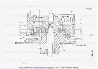
0' mit der geringeren Ringgr·osse befindet sich
hingegen auf der inneren Planseite 14 des Kopfrades. Die H·ohe des
Flansches entspricht bei dieser Anordnung wenigstens der gesamten
Querschnittsh·ohe eines kompletten Transformators.
Eine andere
nicht dargestellte Anordnung sieht eine Flanschh·ohe vor, die etwa nur
der halben Querschnittsh·ohe des Transformators entspricht.
GRUNDIG VIDEO 2X4 STEREO 2200 System for extending the playing time of video cassettes in VIDEO2000 SYSTEM.
A system is provided for extending the playing time of standardized
video cassettes. The system utilizes a rotating head drum having mounted
thereon a first set of video heads displaced 180° with respect to each
other, a second set of video heads displaced by a certain amount from
180° with respect to each other, a rotating winding of a transformer,
and relays to interconnect the heads of either the first or second set
of heads with the rotating winding as the head drum rotates. The relays
are controlled by stationary coils and logic to respond to the setting
of switches to enable the system to operate at normal tape speed via the
first set of heads or reduced tape speed via the second set of heads
without requiring any change in the speed of rotation of the head drum.
1. In a video tape record/playback machine of the type
including a tape transport, a tape transport drive, a rotating head
drum, means for rotating said head drum, a first pair of video heads
mounted on said head drum and displaced from each ot
her by 180°, and a
transformer having a rotating winding mounted to said head drum and a
stationary winding; the improvement comprising: a second pair of video
heads mounted to said head drum and displaced from each other by an
angle slightly different from 180° and control means to interconnect
said first pair of video heads and said rotating winding when said tape
transport drive is operated at a normal speed and to interconnect at
least one of the video heads of said second pair and said rotating
winding when said tape transport drive is operated at a lower, extended
play speed.
2. The machine in accordance with claim 1 wherein said control means comprises:
a first polarized relay affixed to said head drum for rotation
therewith, said first relay having a first position interconnecting said
first pair of video heads to said rotating winding and a second
position interconnecting said second pair of video heads to said
rotating winding;
first and second stationary exciter coils in
controlling relationship with said first relay to drive said first relay
to said first or second position;
switch means having a "normal" position and a "long play" position; and
logic circuit means responsive to the "normal" or "long play" position
of said switch means to activate said exciter coils to drive said first
relay to said first or second position respectively.
3. The machine in accordance with claim 2 wherein said
second pair of video heads comprises a record/playback head and a
playback only head; said switch means further has a "record" position and a "playback" position and further comprising
a second polarized relay affixed to said head drum for rotation
therewith and having a "playback" position interconnecting both heads of
said second pair of video heads with said rotating winding and a
"record" position interconnecting only said record/playback head with
said rotating winding;
said first and second stationary exciter
coils are in controlling relationship with said second relay to drive
said second relay to said "record" or "playback" position; and
said logic circuit means is responsive to said "record" or "playback"
position of said switch to activate said exciter coils to drive said
second relay to said "record" or "playback" position respectively.
4. The machine in accordance wit
h claim 3 wherein said
switch means further includes a "start" position indicating that said
tape transport drive has been activated and said logic circuit means is
responsive to said "start" position of said switch to activate said
exciter coils to drive said first relay to said first position
regardless of whether said switch is in said "normal" or "long play"
position.
5. The machine in accordance with claim 1 further
comprising a servo control connected to said tape transport drive, a
tachometer generator secured to said tape transport drive adapted to
generate pulses responsive to the rotational speed of said drive; a tape
transported past said head drum by said tape transport, said tape
having thereon first and second slant tracks, and the nominal output of
said tachometer generator at said normal and lower speeds are integral
multiples of the frame frequency of said slant tracks.
6. The machine in accordance with claim 5 further comprising:
a divider connected to the output of said tachometer generator, said
divider having a first state to divide the output of said tachometer
generator by a first fixed integer to reduce it to the frame frequency
when said tape transport operates at normal speed and a second state to
divide the output of said tachometer generator by a second fixed integer
to reduce it to the frame frequency when said tape transport operates
at a lower speed;
a comparator having a first input from said
divider, a second input from a reference pulse source, and an output in
controlling relationship with said servo control;
a reference pulse source; and
means for switching said reference pulse source between a first state
to generate reference pulses corresponding to said normal speed and a
second state to generate reference pulses corresponding to said lower
speed.
7. Video tape cassette recorder provided for the use of
standardized V2000 video cassettes and for
extending the playing time of said
video cassettes, said recorder including a tape transport mechanism
capable of driving the tape at a normal standardized speed and at
essentially half the standardized speed, a rotating head drum with a
first pair of video heads displaced from each other by 180° and with a
second pair of video heads displayed from each other by an angle
slightly different from 180° and displaced from said first pair by a
suitable angle; a transformer with one stationary winding and one
rotating winding mounted to said head drum, said head drum being
equipped with a first polarized relay to connect said first or said
second pair of video heads to said rotating transformer winding and with
a second polarized relay to connect one or both of said second pair of
video heads to said rotating transformer winding; said first and said
second polarized relays being displaced from each other by 180° and
being actuated in both positions by first and second stationary coils
excited through logic circuits under the control of position pulses of
said head drum and of the switching mode of operative switches, said
operative switches being shiftable between normal or long play or record
or playback positions.
8. A video tape cassette recorder in accordance with
claim 7 wherein said operative switches include a special switch for the
start and the stop of the tape transport drive; said special switch
being interconnected with said logic circuits so as to connect in the
stop position of said special switch said first pair of video heads to
said rotating transformer winding regardless of whether said respective
operative switch is in the normal or in the long play mode position.
9. A video tape cassette recorder in accordance with
claim 7 further comprising a tachometer generator and a frequency
divider for the output pulses of said tachometer generator; said
tachometer generator being secured to and producing a plurality of
pulses per revolution of said tape transport drive; the frequency of
said tachometer generator output pulses being an integral multiple of
the frame frequency of the video signal at both the rated normal and the
rated low speed of said tape transport drive; and said frequency
divider being switchable between two division factors so as to divide to
frame frequency the frequency of said tachometer generator output
pulses at both, the rated normal and the rated low speed of said tape
transport drive.
Description:
BACKGROUND OF THE INVENTION
The present
invention relates to video tape recording and mor
e particularly to a
system for extending the playing time of standardized video cassettes in
which each of two rotating video heads, displaced relative to each
other by 180°, records or scans one slant track per television field.
In
the standard video cassette intended for home use, a magnetic tape
located in a cassette is utilized. When the cassette is positioned in
the video equipment, the tape is pulled from the cassette and positioned
for operation. In order to permit interchangeability of the cassette
(i.e., in order to insure that a cassette recorded on one machine can be
played back on another machine) certain system standards have been
established which are adhered to by the industry. These standards
include the geometry of the slant tracks, the speed of rotation of the
head drum, the number of video heads mounted on the drum, and the
transport speed of the tape past the head drum. In one popular cassette
system two video heads are mounted on the head drum 180° apart from each
other and displaced to record or scan along one slant track. With 50
fields per second (as is common in most European countries) the head
drum must therefore rotate at 1500 RPM. In order that the common line
interlace of 312.5 lines per field is recorded and reproduced correctly,
a tape speed must be chosen so that the spacing between the tracks (in
the lengthwise direction of the tape) corresponds to an odd multiple of
half lines. In the aforementioned system, this multiple was chosen as
11.
As a result of the above established standards, the maximum
playing time of a cassette is limited to about an hour utilizing the
thinnest tapes available. This playing time is not sufficient for
certain forms of desired programs (e.g., such as full-length motion
pictures). Thus, a considerable need exists for a system to extend the
playing time of a standard cassette while maintaining provision for
normal recording and playback capabilities.
It has heretofore
been propose
d (in German Pat. No. 1,437,141 for example) that the
playing time of a given length of tape could be extended through the
slant track method by recording only the even or odd television fields
but scanning them twice during playback with the tape transport moving
at roughly half the normal speed. In practice, a head drum which rotates
at 1500 RPM and carries two video heads is utilized. The magnetic tape
is looped 180° over the head drum. For recording, only one of the heads
operates while for playing back both heads scan the same track. It is
also known that in this case the two heads must no longer be precisely
180° apart from each other but the additional head position must be
displaced by a slight amount from 180°. In practice this displacement
distance is on the order of a millimeter and thus, it would not be
practical to mount an additional head displaced by this slight amount.
The
principal object of the present invention is to provide an improved
video cassette machine capable of functioning in both a standard normal
mode and an extended play mode.
A further object is to provide
such a machine which can be readily switched from one mode to the other
without requiring any intervention with the drive mechanism of the head
drum.
SUMMARY OF THE INVENTION

The above and
other beneficial objects and advantages are attained in accordance with
the present invention by providing an improved video tape
record/playback machine capable of normal as well as extended play
operation. Video tape record/playback machine includes a tape transport,
a tape transport drive, a rotating head drum, a motor for rotating the
head drum, a first pair of video heads mounted on the head drum and
displaced from each other by 180° of arc, and a transformer having a
rotating winding mounted to the head drum and a stationary winding. In
addition to the above, the present device further includes a second pair
of video heads mounted to the head drum and displaced by an angle
slightly different from 180°. In addition, means are provided to
interconnect the first pair of video heads and the rotating winding when
the tape transport drive is operated at a normal speed and to
interconnect at least one of the video heads of the second set and the
rotating winding of the transformer when the tape transport drive is
operated at a lower, extended play speed. The control means includes a
set of polarized relays affixed to the head drum for rotation therewith
as well as stationary exciter coils which activate the relays. The
exciter coils, in turn, are activated through a control logic circuit
which is governed by switches set at the desired operational mode.
BRIEF DESCRIPTION OF THE DRAWINGS
In the accompanying drawings:
FIG. 1 is a schematic of the head drum and its control logic;
FIG. 2 is a circuit diagram of the switching arrangement between the normal and long playing heads; and
FIG. 3 is a schematic of the tape speed switching arrangement.
DETAILED DESCRIPTION OF THE PREPARED EMBODIMENT
Reference is now made to the drawings wherein similar components bear the same reference numeral throughout the several views.
In FIG. 1, a rotating drum head 1 is shown carrying a first set of heads N
1 and N
2 displaced 180° apart from each other f
1 could theoretically be used with another head displaced slightly apart from N
2 by a distance on the order of 1 millimeter. Since this is not practical to effect, a second set of heads L
1 and L
2 is mounted to the head drum with the displacement between heads L
1 and L
2 being off slightly from 180° as shown. The arrows adjacent to the heads N
1, N
2, L
1 and L
2 depict their operability. Accordingly, heads N
1, N
2 and L
1 are designed for record and playback operation while head L
2 is designed for playback operation only.
or normal (N mode) operation. For long playing (L mode) operation head N
Referring
briefly to FIG. 2, it can be seen that a rotating transformer 2 is
provided with one rotating winding and one stationary winding. Since
rotating multiple transformers are expensive, only a simple transformer 2
is provided. As shown in FIG. 1, a small polarized relay 3 rotates with
the head drum and serves to connect the rotating winding of the
transformer with heads N
1 -N
2 or L
1 -L
2
as required. To this end, the relay 3 is switched by stationary exciter
coils 4 and 5 as the head drum rotates. A second polarized relay 6 is
also provided to connect both heads L
1 and L
2 to the transformer winding during L mode-playback b
ut only head L
1 to the transformer winding during L mode-record. The electrical contacts of the polarized relays 3 and 6 are shown in FIG. 2.
The
logic and switches for the control of the polarized relays 3 and 6 is
depicted in FIG. 1. Thus, as shown, coil 4 is energized by the output of
AND gates 7 or 8. Coil 5 is energized by the output of AND gates 9 or
10. In turn, each of the AND gates 7, 8, 9 and 10 has an input from the
function switches 11 used to determine (a) L or N mode; (b) record or
playback; and (c) whether the tape transport is operative or not.
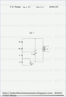
In
addition to the above, gates 7 and 9 each have another input connected
to a position pickup 13. Pickup 13 comprises a simple transducer
designed to generate a pulse each time a small permanent magnet 14 which
rotates with the head drum rotates past the pickup. Thus, the polarized
relay 3 is activated through coils 4 or 5 each time the magnet 14 moves
past the position pickup and is therefore controlled by either the
gates 7 or 9 depending on whether switch 11 is in the "L" or "N"
position.
The output of pickup 13 is also delayed 20 ms through
delay means 12 and then applied to gates 8 and 10. 20 ms corresponds to
the time it takes for the drum head 1, rotating at 1500 RPM, to rotate
through 180°. Thus, 20 ms or half a head drum rotation after relay 3 is
excited by coils 4 or 5, relay 6 is excited by coils 4 or 5.
In N mode (i.e., switch 11 at N position) the electrical contacts of relay 3 are switched to N thereby connecting the heads N
1 and N
2
in series with the rotating transformer. The position of the contacts
of relay 6 is immaterial since in N position relay 3 shunts past heads L
1 and L
2. The operation of the cassette system then proceeds in a conventional manner.
In
L mode -- record, (switch 11 at L and "record") the electrical contacts
of relay 3 are switched to the L position via the AND gate 15, the OR
gate 16 and AND gate 9. After 20 ms, relay 6 is energized via gates 15
and 8 and the head L
1 is thereby connected to rotating transformer 2.
In
L mode -- playback (switch 11 at L and "playback") one must
differentiate between the tape in the running or stopped condition. The
latter would occur, for example, for the reproduction of still pictures.
It has been found that with the magnetic tape stopped, even when in the
"L" mode, the N heads must be utilized since the L heads will
incorrectly scan the tracks resulting in phase shift and poor signal to
noise ratio. Thus, if switch 11 is in the L mode -- playback position
but the tape drive is not started, relay 3 is switched to the N position
via inverted AND gate 17, AND gate 18, and AND gate 7.
When the
tape drive is started (and switch 11 is thus in the L mode -- playback,
tape start position) the relay 3 is switched to the L position via AND
gate 19, OR gate 16 and AND gate 9. In addition 20 ms later relay 6 is
energized to the playback position via AND gate 10 so that the two heads
L
1 and L
2 are connected in series with the transformer coil 2.
In
both the N and L modes of operation the start of ea
ch slant track has
to coincide with the start of a field and hence phase control of the
head drum 2 is required. This is accomplished by means of a phase
comparator 20 which compares pulses from the pickup 13 with reference
pulses from an outside reference source 21. The reference pulses could,
for example, comprise the vertical synchronous pulses separated from the
video signal. The output of the comparator 21 is fed to an amplifier 22
which feeds the drive motor 23 of the head drum 1.
A phase
shifter 24 is provided between the comparator 20 and pickup 13 to
compensate for tolerances of the apparatus. The phase difference
corresponding to the angle α in FIG. 1 which occurs in the transition
from N to L operation is compensated for via switch 25.
Usually,
during recording, the servo control of the tape transport motor compares
the frequency and phase of the actual values of a tachometer generator
coupled with the transport shaft with reference values which generally
are derived from the frame frequency and which are simultaneously
recorded on the magnetic tape as a separate synchronization track. Here
the control accuracy of the tape transport becomes greater, the larger
the number of pulses which are delivered by the tachometer generator per
revolution of the transport shaft. The previously mentioned conditions
for the mutual spacing of the slant tracks recorded on the tape and the
dependence of this spacing on line duration also applies analogously to
L-operation. Howe
ver, since in L-operation only every other field is
recorded the track spacing, as measured in the lengthwise direction of
the tape, must now correspond to an odd multiple of whole lines. The
result is that the transport velocity of the magnetic tape in
L-operation must not be exactly equal to one-half of that in
N-operation, but may be somewhat greater or smaller.
In the
present case with a track spacing in N-operation corresponding to 11
half-lines, a track spacing corresponding to five whole lines must
therefore be chosen in L-operation, i.e., the speed of rotation of the
transport shaft must be reduced in the ratio of 5:11. The frequency of
the pulses delivered by the tachometer generator is thereby also
decreased in the ratio of 5:11.
In order to carry out the
switching of the speed between N- and L- operation as simply as possible
and, also, by purely electrical means, the number of tachometer pulses
per revolution of the transport shaft is chosen so that the tachometer
pulse frequencies which occur at the desired speed of the magnetic tape
in N- and L- operation are integral multiples of the frame frequency.
If, therefore, Z is the number of tachometer pulses per revolution of
the transport shaft, and if n
N and n
L are its speed of rotation in N- and L-operation, the following is to apply: Z
. n
N = p . 25 and Z
. n
L = q
. 25,
where
p and q are integral numbers and 25 Hz is the frame frequency. Since
the ratio of the speeds of rotation is the same as that of the line
numbers corresponding to the track spacings, therefore, in the example
above n
N /n
L = 11/5 and p/q = 11/5.

FIG. 3
shows the circuit diagram of the transport shaft control and of the
transport speed switching arrangement. For simplicity, only the
recording operation is shown. Motor 26 drives the magnetic tape in the
direction of the arrow via the transport shaft 27 and a rubber pressure
roller (not shown). A tachometer generator is coupled to the transport
shaft. This may consist of a ferromagnetic gear 29 and a pickup 30 which
generates pulses in response to rotation of the gear. The tachometer
pulses are fed via an amplifier 31 to a frequency comparator 32 and a
switchable frequency divider 33. The time constant of an R-C circuit or
the charging time of a capacitor can serve as the reference for
comparator 32. Both of these can be adjusted by simple means via the
double-throw switch 34 to the pulse frequencies coming from pickup 30 in
N- or L-operation. A divider 33 divides the tachometer pulse frequency
down to the frame frequency, where the division ratio can be changed by
means of switch 35 from p:1 in N-operation to q:1 in L-operation. The
actual frame frequency appearing at the output of divider 33 is
phase-compared in comparator 36 with the reference frame frequency and
the error signal so produced also serves as an input to control the
frequency comparator 32.
The reference frame frequency is
obtained in the frequency divider 37 by halving the vertical blanking
frequency, which is separated from the video signal to be recorded and
is fed to the terminal 38. This frame frequency is recorded at the same
time on the tape 28 as the sychronization track 40 via the stationary
magnetic head 39. The resulting error signal produced in 32 controls the
motor 26 via the control amplifier 41.
With the numbers given
above, the number of teeth of the ferromagnetic gear tachometer 29 can,
for example, be chosen as 110. If the desired speed of rotation of the
motor 26 is 750 RPM in N-operation, p = 55 and q = 25 for the divider
33.
The switches 34 and 35 shown in FIG. 3 can be ganged to
operate together with the N/L switch 11. To prevent operating errors, it
is advisable, however, to operate the switch 25 via the control logic
rather than manually.
Thus in accordance with the above, the aforementioned objectives are effectively attained.
GRUNDIG VIDEO 2X4 STEREO 2200 Helical scan apparatus for video tape
or the like and having rotating-head inclination-adjustment means:
A helical scan recording and playback apparatus wherein magnetic video
tape forms a helix about the peripheral surfaces of two coaxial drums
which define an annular gap for magnetic heads which orbit in a chamber
between the drums and engage inclined tracks at the inner side of the
helix. The heads are mounted on a disk which is rotatable on a sleeve
surrounding with clearance a shaft for the drums and having an internal
protuberance which is tiltable with respect to the periphery of the
shaft by a rod extending through an opening in the flange of one of the
drums. The inclination of the plane of orbital movement of the heads
relative to the central symmetry plane of the gap is changed when the
speed of lengthwise movement of tape during playback deviates from the
speed of lengthwise movement of tape during recording.
1. In a helical scan apparatus wherein information is
recorded on or reproduced from magnetic tape which is moved lengthwise
and forms a helix about the peripheral surfaces to two coaxial drums
which surround a shaft, wherein the peripheral surfaces of said drums
define an annular gap for at least one magnetic head which orbits in a
first plane and thereby engages inclined tracks of said helix, and
wherein said gap has a central symmetry plane which is normal to the
common axis of said drums, a combination comprising a carrier for said
head, said carrier being disposed between said drums; means for rotating
said carrier to thereby orbit said head along said gap; and means for
changing the inclination of said first plane relative to said symmetry
plane when the speed of tape movement during reproduction deviates from
the speed of tape movement during recording so as to conform the path of
said head to the inclination of tracks on said helix, comprising a
bearing assembly for said carrier and including a sleeve intermediate
said drums and rotatably supporting said carrier coaxial with the same,
said sleeve having an internal surface spacedly surrounding said shaft
and having a protuberance tiltably engaging the periphery of said shaft,
and tilting means actuatable for tilting said bearing assembly with
respect to the common axis of said drums to thereby change the
inclination of said sleeve.
2. A combination as defined in claim 1, wherein said protuberance is an annulus.
3. A combination as defined in claim 1, wherein said
protuberance engages said shaft in said symmetry plane.
4. A combination as defined in claim 1, wherein said protuberance is a bearing.
5. A combination as defined in claim 1, further
comprising means for yieldably urging said sleeve to a position in which
said carrier is coaxial with said drums.
6. A combination as defined in claim 1, wherein one of
said drums has an opening and said tilting means comprises a rod rigid
with said sleeve and extending through said opening.
7. A combination as defined in claim 1, further
comprising antifriction bearing means interposed between said carrier
and said sleeve.
8. A combination as defined in claim 1, further
comprising an energy source for said head, including a rotor mounted on
said carrier and electrically connected with said head and a stator
mounted on said bearing assembly adjacent to said rotor.
Description:
BACKGROUND OF THE INVENTION
The present
invention relates to apparatus for recording and/or reproducing
high-frequency information on magnetic tape, and more particularly to a
mechanism for guiding magnetic tape and one or more magnetic heads in
such apparatus.
It is already known to guide magnetic tape along
the peripheral surfaces to two coaxial drums which define an annular gap
for one or more magnetic heads mounted in the interior of the drum and
serving to record or reproduce information on the tape. The diameters of
the peripheral surfaces are identical or nearly identical and the
portion of tape which engages such peripheral surfaces forms a helical
loop (e.g., an alpha loop or an omega loop). One of both drums may be
driven or head against rotation about their common axis. The magnetic
head or heads are mounted on a carrier or bracket which relates about
the common axis of and is located between the drums. The plane in which
the carrier rotates the head or heads coincides with the central plane
of the gap between the peripheral surfaces of the drums.
In
recording-reproducing apparatus which employ video tape, the speed at
which the tape moves during recording may but need not equal the tape
speed during reproduction. Thus, it is often desired to accelerate the
reproduction, to make slow-motion reproductions of recorded information
or to reproduce still images of a particular subject or scene. This
creates problems in the aforedescribed apparatus wherein the tape
portions which is trained around the peripheral surfaces of the drums
forms a helix. As is known, such guidance of the tape is desirable
because it allows for relatively high signal density in each of the scan
lines which is particularly desirable in connection with recording of
television signals, i.e., an entire image can be recorded on a single
relatively long track. The track makes an acute angle with the marginal
portions of the tape. The inclination of the track is determined
primarily by two factors, namely by inclination of the tape with respect
to the common axis of the drums and by speed of lengthwise movement of
the tape. If the direction of movement of the tape about the drums is
identical with the direction of rotation of the heads, the inclination
of the track with respect to the marginal portions of the tape increases
with increasing speed of the tape. On the other hand, the inclination
of the track decreases if the tape is being advanced counter to the
direction of rotation of the heads and the speed of the tape incr
eases.
If
the speed of reproduction in a video system is less than the speed
during recording, i.e., if the reproduction is to furnish a slow-motion
or still-image effect, portions of the heads leave the adjacent tracks
with the result that the quality of a substantial portion of the
reproduced image is less than satisfactory, i.e., the reproduction takes
place with a much less satisfactory signal to noise ratio.
Certain
presently known helical scan apparatus are equipped with complex and
expensive electronic systems which are designed to compensate for or
suppress the just described phenomena. It is also known to employ a
mechanical compensating system which is designed to change the path of
tape with respect to the drums, i.e., to change the lead of the helical
loop which engages the drums. Such proposal is not satisfactory because
the tape undergoes undesirable deformation and also because the change
in lead is not reproducible, with a requisite degree of accuracy owing
to friction with the drums.
SUMMARY OF THE INVENTION
An
object of the invention is to provide an apparatus which insures proper
registry o
f magnetic heads with the inclined track on a helically wound
magnetic tape by resorting to a small number of simple, rugged and
inexpensive parts.
Another object of the invention is to provide s
single mechanical device which maintains the magnetic heads of a
helical scan apparatus in accurate register with the track even if the
speed of magnetic tape during reproduction varies and deviates from the
speed during recording.
A further object of the invention is to
provide a helical scan apparatus with a device which insures accurate
register of the magnetic head with inclined tracks on a helically looped
magnetic tape during reproduction with slow-motion, still-image and/or
acceleration effect.
The invention is embodied in a helical scan
apparatus wherein information is recorded on or reproduced from magnetic
tape which is moved lengthwise and forms a helix about the peripheral
surfaces of two coaxial drums, wherein the peripheral surfaces of the
drums define an annular gap for at least one magnetic head which orbits
in a first plane and thereby engages inclined tracks at the inner side
of the helix, and wherein the gap has a central symmetry plane which is
normal to the common axis of the drums. The apparatus comprises a
carrier (e.g., a disk) which supports the head or heads and is located
between the drums, a belt transmission or analogous means for rotating
the carrier to thereby orbit the head or heads along the gap, and means
for changing the inclination of the first plane with respect to the
symmetry plane of the gap when the speed of tape movement during
reproduction (playback) deviates from the speed of tape movement during
recording so as to conform the path of orbital movement of the head or
heads to the inclination of tracks on the helix.
The inclination
changing means preferably comprises a bearing assembly for the carrier
and means for tilting the bearing assembly with respect to the common
axis of the drums.
The drums are mounted on a common shaft and
the bearing assembly preferably comprises a sleeve which is disposed
intermediate the drums and rotatably supports the carrier. The sleeve
has an internal surface which spacedly surrounds the shaft and has a
preferably annular protuberance (e.g., a spherical or prismatic bearing)
which tiltably engages the periphery of the shaft. The tilting means is
actuatable to change the inclination of the sleeve which is coaxial
with the carrier so that the inclination of the first plane with respect
to the symmetry plane changes in response to tilting of the sleeve. The
protuberance is preferably located in or immediately adjacent to the
symmetry plane. The sleeve is held against axial movement relative to
the shaft.
The novel features which are considered as
characteristic of the invention are set forth in the appended claims.
The improved helical scan apparatus itself, however, both as to its
construction and its mode of operation, together with additional
features and advantages thereof, will be best understood upon perusal of
the following detailed description of certain specific embodiments with
reference to the accompanying drawing.
BRIEF DESCRIPTION OF THE DRAWING
FIG. 1 is a fragmetary partly diagrammatic axial sectional view of a helical scan apparatus which embodies the invention; and
FIG. 2 is a smaller-scale plan view of the apparatus.
DESCRIPTION OF THE PREFERRED EMBODIMENTS
FIG.
1 shows a portion of the improved helica

l scan apparatus which
comprises two coaxial drums 1 and 1' having peripheral surfaces 1A, 1A'
of identical or nearly identical diameter and serving to guide a video
tape 20 (FIG. 2) which can form a so-called alpha or a so-called omega
loop (omega loop shown in FIG. 2). The drums 1 and 1' are mounted on a
common shaft 2 and their peripheral surfaces 1A, 1A' are spaced apart to
define an annular clearance or gap 3 surrounding the endless path of
one or more magnetic heads 4 mounted on a disk-shaped carrier 5 which is
tiltably mounted on the shaft 2 in the chamber or space 101 defined by
the drums 1 and 1'. As a rule, the carrier 5 supports two heads 4 which
are located diametrically opposite each other with respect to the axis
of the shaft 2. The hub 5a of the carrier 5 is mounted on two
antifriction ball bearings 6, 6' which surround a tiltable bearing
sleeve 7 mounted in the chamber 101 and having an internal surface
surrounding, with certain clearance, the shaft 2.
The energy
source for the head or heads 4 includes a transformer having a rotor 8
mounted on the carrier 5 and a stator 9 mounted in the drum 1'. The
means for rotating the carrier 5 includes a drive having a motor 19
(FIG. 2) an endless belt or cord 10 engaging a sheave-like portion of
the hub 5a.
The internal surface of the bearing sleeve 7 has an
annular bearing portion or protuberance 11 which engages with the
peripheral surface of the shaft 2 in or very close to the central
symmetry plane X--X of the gap 3. The aforementioned clearance between
the internal surface of the bearing sleeve 7 and the peripheral surface
of the shaft 2 has a first portion at one side and a second portion at
the other side of the bearing portion 11. The upper end of the bearing
sleeve 7 (as viewed in the drawing) has a larger-diameter portion or
collar 13 which is connected with a pin- or rod-shaped tilting member 12
extending with clearance through an opening ID' in the flange 1B' of
the drum 1'. If the member 12 is pushed or pulled in the direction
indicated by arrow A or B, or moved axially, the sleeve 7 is tilted with
respect to the shaft 2 and thereby changes the inclination of the plane
of orbital movement of heads 4 with respect to the symmetry plane X--X
of the gap 3. Thus, by moving the member 12, one can move the
tape-contacting portion of the head 4 above or below the central plane
of the gap 3. This enables the head 4 to conform to the changed position
of scan lines on video tape 20 which is being moved along the gap 3,
with or relative to the peripheral surface 1A and/or 1A'. The position
tracks on the tape with respect to the head 4 changes if the speed of
tape, during reproduction of information, deviates from the speed during
recording. A package of dished springs 14 is interposed between the
flange 1B' and the collar 13 to bear against the collar and to bias the
sleeve 7 to a desired neutral position while permitting for tilting of
the sleeve in response to shifting of the member 12. The carrier 5
shares the tilting movements of sleeve 7 under the action of the member
12. In FIG. 1, the plane of orbital movement of the heads 4 coincides
with the symmetry plane X--X.
FIG. 2 shows that the tape 20 is
being paid out by a supply reel 21 and is being collected by a takeup
reel 22. The means for moving the tape 20 lengthwise comprises a pinch
roller 23, a capstan 24 and a motor 25 which drives the capstan 24.
Rollers 26 guide the tape 20 between the reel 21 and the peripheral
surfaces 1A, 1A' of the drums 1, 1' (only the drum 1' is shown in FIG.
2) as well as between such peripheral surfaces and the capstan 24. The
carrier 5 is driven by the aforementioned motor 19. The means for
tilting or otherwise moving the rod 12 relative to the shaft 2 is not
shown in FIG. 2.
The tiltable mounting of carrier 5 with bearing
assembly 6, 6', 7, 11 can be modified in a number of ways without
departing from the spirit of the invention. For example, the
antifriction bearings 6, 6' can be replaced with a single bearing
located in the plane of the gap 3. Moreover, one can replace the
protuberance 11 with a tiltable prismatic or spherical antifriction
bearing. All that counts is to ins
ure that the carrier 5 can be tilted
relative to the gap 3 and preferably rotated relative to the shaft 2
while the helical scan apparatus is in use. It has been found that the
illustrated arrangement performs quite satisfactorily and can stand long
periods of use.
Without further analysis, the foregoing will so
fully reveal the gist of the present invention that others can, by
applying current knowledge, readily adapt it for various applications
without omitting features which fairly constitute essential
characteristics of the generic and specific aspects of my contribution
to the art and, therefore, such adaptations should and are intended to
be comprehended within the meaning and range of equivalence of the
claims.
What is claimed as new and desired to be protected by Letters Patent is set forth in the appended claims.
GRUNDIG VIDEO 2X4 STEREO 2200 Device for the track following of rotating magnetic heads SYSTEM VIDEO2000. (DYNAMIC TRACK FOLLOWING)
1. Device for the track following of rotating magnetic heads (2,
3) in magnetic tape devices, in which piezoelectric elements (4, 5) are
used as carriers of the magnetic heads, are clamped at one end firmly
in a rotating holder and are connected at their deflectable end to the
magnetic head, the free length (b) of the piezoelectric elements (4, 5)
running at an angle to the joining line between assigned magnetic head
and point of rotation of the rotating holder, to increase the
deflection,
characterized in that the free length (b) of the
piezoelectric elements (4, 5) extends up to approximately level with the
point of rotation and in that, to compensate for azimut errors, the
piezoelectric elements (4, 5) are clamped into the rotating holder (1)
at such an angle that the clamping lengths (a1 , a2 ) at the edges of
the respective piezoelectric element are of different sizes.
EINRICHTUNG F·UR DIE SPURNACHESHRUNG VON
ROTIERENDEN MAGNETK·OPFEN PATENTANSPR·UCHE
1. Einrichtung f·ur die Spurna
chf·uhrung von rotierenden
Magnetk·opfen in Magnetbandger·aten, bei der als Tr·ager der
Magnetk·opfe Piezoelemente verwendet sind, die an einem Ende fest in
einer rotierenden Halterung eingespannt und an ihrem auslenkbaren Ende
mit dem Magnetkopf verbunden sind, d a d u r c h g e k e n n z e i c h n
e t , dass zur Erh·ohung der Auslenkung die freie L·ange (b) der
Piezoelemente (4, 5) schr·ag zur Verbindungslinie (6, 7) zwischen
zugeordnetem Magnetkopf (2, 3) und Drehpunkt (8) der rotierenden
Halterung (1) bis etwa in der H·ohe dieses Drehpunktes verl·auft, und
dass zur Kompensation von Azimutfehlern die Piezoelemente schr·ag (a1,
a2) in die rotierende Halterung eingespannt sind.
2. Einrichtung nach Anspruch 1, d a d u r c h g e k e n n
z e i c h n e t , dass die rotierende Halterung der Piezoelemente fest
mit einem rotierenden Kopfrad (1) verbunden ist.
Description:
EINRICHTUNG F·UR DIE SPURNACHF·UHRUNG VON ROTIERENDEN
MAGNETK·OPFEN BESCHREIBUNG Die Erf
indung betrifft eine Einrichtung f·ur
die Spurnachf·uhrung von rotierenden Magnetk·opfen in
Magnetbandger·aten, bei der als Tr·ager der Magnetk·opfe Piezoelemente
verwendet sind, die an einem Ende fest in einer rotierenden Halterung
eingespannt und an ihrem auslenkbaren Ende mit dem Magnetkopf verbunden
sind.
Seit einiger Zeit werden beispielsweise in Videorecordern
zur Spurnachf·uhrung Piezoelemente (in diesem Zusammenhang auch
"Aktuatoren" oder Bimorphe" genannt) verwendet, an deren
freischwingenden Enden die Magnetk·opfe befestigt sind. Die
Piezoelemente weisen die Eigenschaft auf, dass sie beim Anlegen einer
Spannung je nach Polarit·at in die eine oder andere Richtung ausgelenkt
werden, so dass die Magnet k·opfe senkrecht zur Abtastrichtung bewegt
werden k·onnen. Steuert man die Piezoelemente mit einer Regelspannung
entsprechend dem Spurfehler an, so folgen die Videok·opfe genau den
vorgesehenen Spuren.
An ihren anderen Enden sind die Piezoelemente
fest in einen Piezoeiementhalter eingespannt, der entweder selbst
rotiert oder starr mit dem rotierenden Kopfrad des Videorecorders
verbunden ist. Die freischwingende L·ange des Piezoelementes ist ein
Mass f·ur die erreichbare Kopfauslenkung.
Die Figuren 1 und 2
zeigen bekannte Anordnungen zur Spurnachf·uhrung in Videorecordern. Die
Magnetk·opfe 2 und 3 sind an den freischwingenden Enden der
Piezoelemente 4 und 5 befestigt (z. B. aufgeklebt). Die freischwingenden
L·angen der Piezoelemente sind mit b bezeichnet. An ihren anderen Enden
sind die Piezoelemente in einen Piezoelementhalter 1 eingesp
annt, der
entweder selbst als rotierendes Teil ausgebildet oder mit dem
rotierenden Kopfrad des Videorecorders starr verbunden ist. Die
Einspannl·ange der Piezoelemente in die Piezoelementhalter ist mit a
bezeichnet.
Neuere Trends in der Video technik f·uhren zu immer
kleineren Kopf r·adern, was zur Folge hat, dass die freischwingenden
L·angen der Piezoelemente und damit auch die erreichbare Kopfauslenkung
immer kleiner wird.
Der vorliegenden Erfindung liegt deshalb die
Aufgabe zugrunde, eine Einrichtung zur Erh·ohung der
Piezoelementauslenkung zu schaffen, die sich insbesondere f·ur kleine
Magnetbandger·ate eignet, billig ist und eine praktisch
azimutfehlerfreie Wiedergabe der magnetisch aufgezeichneten Signale
erm·oglicht.
Diese Aufgabe wird nach der vorliegenden Erfindung
dadurch gel·ost, dass die Piezoelemente schr·ag zur Verbindungslinie
zwischen zugeordnetem Magnetkopf und Drehpunkt der rotierenden Halterung
bis etwa in die H·ohe dieses Drehpunktes verlaufen und dass die
Piezoelemente zur Vermeidung von Azimutfehlern schr·ag in die rotierende
Halterung eingespannt sind.
Die Vorteile der Erfindung liegen
darin, dass insbesondere bei Magnetbandger·aten mit kleinen Kopfr·adern
die freischwingenden L·angen der Piezoelemente und damit die erreichbare
Auslenkung vergr·ossert wird.
Im folgenden wird ein
Ausf·uhrungsbeispiel f·ur die vorliegende Erfindung mit Hilfe der Figur 3
n·aher erl·autert. Die Magnetk·opfe 2 und 3 sind an den
freischwingenden Enden der Piezoelemente 4 und 5 befestigt. Die
freischwingenden L·angen'der Piezoelemente sind mit b bezeichnet.
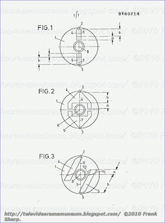
Durch
die Anordnung der Piezoelemente 4, 5 schr·ag zur Verbindungslinie 6, 7
zwischen zugeordnetem Magnetkopf 2, 3 und Drehpunkt 8 der rotierenden
Halterung 1 bis etwa in H·ohe dieses Drehpunktes wird die
freischwingende L·ange jedes Piezoelementes vergr·ossert. An ihren
anderen Enden sind die Piezoelemente in den Piezoelementhalter 1
eingespannt.
Diese Einspannung erfolgt im Gegensatz zum Stand der
Technik schr·ag, um die sonst bei der Auslenkung der Piezoelemente zu
erwartenden Azimutfehler der Magnetk·opfe zu kompensieren. Damit wird
eine praktisch azimutfehlerfreie Wiedergabe der magnetisch
aufgezeichneten Signale erm·oglicht. Die Einspannl·ange, unter der hier
der Mittelwert der Strecken al und a2 verstanden wird, ist mit a
bezeichnet.
Mit einer Anordnung nach der vorliegenden Erfindung
wird erreicht, dass im Vergleich zum Stand der Technik bei sonst
gleichen Bedingungen (insbesondere bei gleicher Regelspannung)die
erreichbare Auslenkung der Piezoelemente vergr·ossert wird.
Die
Erfindung ist nicht auf das vorliegende Ausf·uhrungsbeispiel
beschr·ankt. Beispielsweise spielt es keine Rolle, welcher Art die
Verbindungen zwischen Magnetkopf und Piezoelement sowie Piezoelement und
Piezoelementhalter sind.
GRUNDIG VIDEO 2X4 STEREO 2200
SYSTEM VIDEO2000 Scan
tracking arrangement for videorecorders using piezoelectric elements.
1. Scan tracking arrangement in video recorders having a rotating head
wheel, in which arrangement the magnetic heads are attached to
piezoelectric elements and each head has a tape contact phase and a
non-contact phase during one full revolution of the head wheel, and in
which arrangement a voltage which holds the head on the intended track
is applied to the piezoelectric element of a head which is in tape
contact at that time, and in which arrangement a decaying alternating
voltage for eliminating hysteresis effects of the piezoelectric element
is applied ot the piezoelectric element of a head which is not in tape
contact at that time, characterized by the following features : the
decaying alternating voltage is rectangular and the frequency of the
decaying alternating voltage for eliminating hysteresis effets of the
piezoelectric element is just below the frequency of mechanical
renonance of the piezoelectric element.
1. ANORDNUNG ZUR SPURNACHF·UHRUNG IN VIDEORECORDERN UNTER
VERWENDUNG VON PIEZOELDIENTEN PATENTANS PRUCH Anordnung zur
Spurnachf·uhrung in Videorecordern mit einem rotierenden Kopfrad, wobei
die Magnetk·opfe an Piezoelementen befestigt sind und jeder Kopf
w·ahrend einer Vollumdrehung des Kopfr
ades eine Bandeingriffphase und
eine Nichteingriffphase hat, und wobei an das Piezoelement eines Kopfes,
der gerade im Bandeingriff steht, eine Spannung angelegt wird, die den
Kopf auf der vorgesehenen Spur h·alt, und wobei an das Piezoelement
eines Kopfes, der gerade nicht im Bandeingriff steht, eine abklingende
Wechselspannung zur Beseitigung von Hystereseeffekten des Piezoelementes
angelegt wird, gekennzeichnet durch die folgenden Merkmale: : - die
abklingende Wechselspannung ist rechteckf·ormig und - die Frequenz der
abklingenden Wechselspannung zur Beseitigung von Hystereseeffekten des
Piezoelemen tes liegt knapp unterhalb der mechanischen Reso nanzfrequenz
des Piezoelementes.
Description:
ANORDNUNG ZUR SPURNACHF·UHRUNG IN VIDEORECORDERN UNTER
VERWENDUNG VON PIEZOELEMENTEN BESCHREIBUNG Die Erfindung betrifft eine
Anordnung zur Spurnachf·uhrung in Video
recordern mit einem rotierenden
Kopfrad, wobei die Magnetk·opfe an Piezoelementen befestigt sind und
jeder Kopf w·ahrend einer Vollumdrehung des Kopfrades eine
Bandeingriffphase und eine Nichteingriffphase hat, und wobei an das
Piezoelement eines Kopfes, der gerade imBandeingriff steht, eine
Spannung angelegt wird, die den Kopf auf der vorgesehenen Spur h·alt,
und wobei an das Piezoelement eines Kopfes, der gerade nicht im
Bandeingriff steht, eine abklingende Wechselspannung zur Beseitigung des
Hystereseeffektes des Piezoelementes angelegt wird.
Seit einiger
Zeit werden in Videorecordern zur exakten Spurhaltung Piezoelemente (in
diesem Zusammenhang auch "Aktuatoren" oder Eimorphe" genannt) verwendet,
auf denen die Magnetk·opfe befestigt sind. Die Piezoelemente weisen die
Eigenschaft auf, dass sie beim Anlegen einer Spannung je nach
Polarit·at in die eine oder in- die andere Richtung ausgelenirwerden, so
dass die Magnetk·opfe senkrecht zur Abtastrichtung bewegt werden
k·onnen. Steuert man die Piezoelemente mit einer Regelspannung
entsprechend dem Spurfehler an, so folgen die Videok·opfe genau den
vorgesehenen Spuren.
Aus der europ·aischen Offenlegungsschrift mit
der Publikationsnummer 0091 750 ist eine Anordnung zur Spursteuerung
bekannt, bei der ein auf einem Piezoelement befestigter Magnetkopf
w·ahrend der Bandeingriffsphase durch das Anlegen einer positiven oder
negativen Gleichspannung an eine vorgegebene Stelle gebracht wird. Nach
dem Abschalten dieser Gleichspannung am Beginn der Nichteingriffsphase
kehrt die Kopf-Piezoelement-Einheit nicht wieder exakt in ihre
Ausgangsposition zur·uck, da aufgrund des Hystereseeffektes im
Piezoe
lement eine Restauslenkung verbleibt, die die Nullpunktlage der
Kopf-Piezoelement-Einheit ver·andert. Demzufolge werden bei der
n·achsten Bandeingriffsphase dieses Kopfes Spurfehler auftreten.
Um
diese m·oglichst schnell auszuregeln, ·uberlagert man der an das
Piezoelement angelegten Gleichspannung w·ahrend der Nichteingriffsphase
eine abklingende sinusf·ormige Wechselspannung. Nach dem Abklingen
dieser sinusf·ormigen Wechselspannung liegt am Piezoelement die Spannung
an, die die jeweils geforderte Ablenkung des Magnetkopfes bewirkt.
Des
weiteren ist aus der europ·aischen Offenlegungsschrift mit der
Publikationsnummer 0091 764 eine Vorrichtung bekannt, die ebenso wie der
Erfindungsgegenstand zur Spurregelung den Piezoeffekt ausnutzt.
Bei
der bekannten Vorrichtung sind zwei um 180 Grad versetzte Magnetk·opfe
an Piezoelementen befestigt, die ihrerseits fest mit dem Kopfrad
verbunden sind.
Zur Vermeidung eines Spurfehlers bei im Vergleich
zur Aufzeichnung unterschiedlicher Wiedergabegeschwin digkeit wird an
die beiden Piezoelemente w·ahrend des jeweilyFn Bandeingriffs ein
dreieckf·ormiges Spurkorrektursignal angelegt. W·ahrend des Nicht
eingriffs beh·alt das Piezoelement und damit auch der daran befestigte
Magnetkopf eine Restauslenkung, so dass auch bei dieser Anordnung die
Nullpunktlage der Kopf Piezoelement-Einheit ver·andert wird, was am
Beginn der n·achsten Bandeingriffsphase des Magnetkopfes zu einem
Spurfehler f·uhrt.
Zur Vermeidung dieses Spurfehlers am Beginn der
n·achsten Bandeingriffsphase wird dem Piezoelement w·ahrend der
Nichteingriffsphase eine abklingende sinusf·ormige Wechselspannung
zugef·uhrt, die die fehlerhafte Nullpunktlage der Kopf
Piezoelement-Einheit beseitigt, d. h. die Restauslenkung des Kopfes
r·uckg·angig macht, so dass der Kopf am Beginn der n·achsten
Bandeingriffsphase genau die jewei1ige Soll-Spur ·ubereckt. Die bekannte
Vorrich tung enth·alt weiterhin eine Umpolvorrichtung, die in
Abh·angigkeit davon, ob das Piezoelement in die eine oder in die andere
Richtung ausgelenkt wurde, d. h.
die Wiedergabegeschwindigkeit
kleiner oder gr·osser als die Aufzeichnungsgeschwindigkeit war, dem
Piezoelement eine geeignet gepolte Spannung zur Beseitigung von
Hystereseefekten zuf·uhrt. Es zeigt sich also, dass der Versuch, die
Hystereseefekte ohne Verwendung, einer Umpolvorrichtung f·ur die abkleme
Weckselspannung zu beseitigen, noch keine zufried stellenden Ergebnisse
bringt.
Ausgehend von diesem Stand der Technik liegt der
vorliegenden Erfindung die Aufgabe zugrunde, eine verbesserte Anordnung
zur Beseitigung von Hysterese- effekten einer Kopf-Piezoelement-Einheit
zu schaffen, mit der auch ohne Verwendung einer Umpolvorrichtung die
Hystereseefekte der Kopf-Piezoelement- Einheit vollst·andig beseitigt
werden.
Die L·osung dieser Aufgabe erfolgt durch die kennzeichneneden Merkmale des Patentanspruchs.
Die
Vorteile der Erfindung liegen nicht nur darin, dass die Videnkopfe am
beginn ihrer n·achsten Bandeingriffsphase an ihrer Sollposition stehen,
sondern in der mehrere auch darin dass eine Desensibilizierung der
Piezoelment verwenden wird, also keine Verringerung der Empfindlichkeit
gegen·uber der angeleg ten Spannung auftritt, was bei einem l·angeren
Anlie gen einer Spannung (insbesondere einer hohen Gleich spannung) an
einem Piezoelement der Fall sein k·onnte.
im folgenden wird die
Erfindung an einem Ausf·uhrungs beispiel n·aher erl·autert. Dabei
zeigen: Fig. 1 ein Blockschaltbild mit allen f·ur die Erfindung
wesentlichen Bauteilen und Fig. 2 ein Diagramm, das die Verl·aufe der an
die Piezoelemente angelegten Spannun gen als Funktion der Zeit zeigt.
Im
Ausf·uhrungsbeispiel von Figur 1 wird dem Eingang A eines
Microcomputers 1 eine auf bekannte Art und Weise erzeugte digitale,
impulsbreitenvariable Regelspan nung zugef·uhrt, die eine genaue
Auskunft ·uber die Ab weichung des jeweiligen Magnetkopfes von der Soll
spurlage gibt. Eine detaillierte Beschreibung der Er zeugung einer
derartigen Regelspannung kann beispielsweise der Zeit schrift "Grundig
Technische Informationen" 3/81, S. 110 - 116, entnommen werden.
Der
Microcomputer 1 erzeugt an seinem Ausgang B vom jeweiligen
Betriebszustand (Aufzeichnung, Wiedergabe, Zeitlupe, Zeitraffer)
abh·angige digitale Regelsignale f·ur die ?iezemente. Diese Regelsignale
werden in einem Digital/Analog-Wandler 2 digital-/analog-gewan delt und
zwei Schaltern 3 und 4 zugef·uhrt. Die ·Offnungs- und Schliesszeiten
dieser Schalter sowie der Schalter 5 und 6 werden von den an den
Ausg·angen C und D des Microcomputers 1 anliegenden Steuersignalen
gesteuert. Der Schalter 3 ist immer dann geschlossen, wenn der am
Piezoelement 1 befestigte Kopf im Bandeingriff steht.
Der Schalter
5 befindet sich w·ahrend dieser Zeitspanne in der Stellung b, so dass
die am Ausgang des D/A-Wandlers 2 anliegende Regelspannung ·uber die
Schalter 3 und 5 an das Piezoelement 1 weitergegeben wird und der am
Piezoelement 1 befestigte Magnetkopf der durch die Regelspannung
vorgegebenen Spur folgt.
Ist die Kopf-Piezoelement-Einheit 1 im
Bandeingriff, dann befindet sich die Kopf-Piezoelement-Einheit 2 in
ihrer Nichteingriffsphase. Diese Zeitspanne wird ausgenutzt, um dem
Piezoelement 2 ·uber den Schalter 6, der sich
hierbei in der Stellung b
befindet, eine abklingende rechteckf·ormige Spannung von einem vom
Microcomputer 1 gesteuerten Generator 7 zuzuf·uhren.
Damit wird
eine eventuelle Restauslenkung des zugeharigen Magnetkopf es, die ihre
Ursache in der Hysterese im Piezoelement 2 hat, vollst·andig beseitigt.
Besonders wirkungsvoll ist gem·ass einem Merkmal der Erfindung die
Beseitigung der Hystereseeffekte des Piezoelementes dann, wenn die
Frequenz der angelegten Rechteckspannung knapp unterhalb der
mechanischen Resonanzfrequenz (ungef·ahr 1 kHz) des Piezoelementes
liegt, also beispielsweise in der Gr·ossenordnung von 700 Hz.
Hat der Magnetkopf 1 die Spur zuende gelesen bzw.
geschrieben,
-so findet eine vom Microcomputer gesteuerte Kopfumschaltung statt.
Jetzt wird eine am Ausgang des D/A-Wandlers 2 anliegende analoge
Regelspannung durch den geschlossenen Schalter 4 und den Schalter 6, der
sich in der Stell
ung a befindet, an das Piezoelement 2 weitergeleitet,
so dass der am Piezoelement 2 befestigte Magnetkopf der ihm durch die
Regelspannung aufgepr·agten Spur folgt.
Der Schalter 3 ist in
dieser Phase ge·offnet. Gleichzeitig dazu wird dem Piezoelement 1 ·uber
den Schalter 5, der sich in dieser Phase in der Stellung a befindet,
eine abklingende Rechteckspannung von einem vom Microcomputer 1
gesteuerten Generator 8 zur vollst·andigen Beseitigung des
Hystereseeffektes des Piezoelementes 1 zugef·uhrt, die eine eventuelle
Restauslenkung der Kopf-Piezoelement-Einheit 1 beseitigt, so dass der
Magnetkopf 1 am Beginn seines n·achsten Bandeingriffes an der richtigen
Stelle steht.
Figur 2 gibt einen ·Uberblick ·uber
die an die
Piezoelemente 1 und 2 angelegten Spannungen. Dabei entsprechen die
Zeitintervalle [ t1, t2 ] , [ t3 > t4 ] > [ t5, t6 ] , den
Bandeingriffsphasen der Kopf-Piezoelement-Einheit 1 und den
Nichteingriffsphasen der Kopf-Piezoelement Einheit 2 und die
Zeitintervalle [ t2, t3 ] [ t4, t5 [ t6, t7 ] , den Bandeingriffsphasen
der Kopf-Piezoelement-Einheit 2 und den Nichteingriffsphasen der
Kopf-Piezoelement-Einheit 1.
Die obengenannten Zeitintervalle, die f·ur die Beseitigung der Hystereseeffekte der Piezoelemente 1 bzw.
2
zur Verf·ugung stehen, liegen bei Verwendung von zwei um 180 Grad
versetzten Magnetk·opfen im Normalbetrieb bei 20 msec. Es hat sich
·uberraschenderweise gezeigt, dass eine Beseitigung der Hystereseeffekte
der Piezoelemente besonders wirkungsvoll ist, wenn die-Frequenz der
Spannung zur Beseitigung der Hystereseeffekte knapp unterhalb der
mechanischen Resonanzfrequenz der Piezoelemente gew·ahlt wird, die in
der Gr·ossenordnung von 900 - 1200 Hz liegt, und eine abklingende
Rechteckspannung verwendet wird. Bei der Wahl der Frequenz muss
lediglich darauf geachtet werden, dass keine st·orenden
Resonanzerscheinungen auftreten, d. h. dass die Frequenz nicht zu nahe
bei der mechanischen Resonanzfrequenz der Piezoelemente liegt.
W·ahlt
man beispielswelse 700 Hz, dann betr·agt die Dauer einer Schwingung 1,4
msec. In der zur Verf·u gung stehenden Zeitspanne von 20 msec. w·are
somit eine Beseitigung der Hystereseeffekte mit ca. 14 Schwingungen
m·oglich.
Der exakte Verlauf des Abklingvorganges (Verlauf der
Einh·ullenden der abklingenden Rechteckspannung) richtet sich nach den
physikalischen Eigenschaften des jeweils verwendeten Aktuatormaterials.
Es ist in jedem Fall darauf zu achten, dass die Amplitude der letzten
Rechteckschwingung hinreichend klein gew·ahlt wird.
Bei einigen
neueren Entwicklungen im Videobereich (z. B. Kamerarecorder) werden
immer kleinere Kopfr·ader verwendet und es liegt eine ·Uberumschlingung
des Magnetbandes um das Kopfrad vor. Demzufolge werden die
Nichteintauchphasen der Kopf-Piezoelement Einheiten und damit die zum
Beseitigen der Hystereseeffekte zur Verf·ugung stehenden Zeitintervalle
kleiner. Auch werden bei einigen neueren Trends die Zeitintervalle, in
denen Spannungen (insbesondere Gleichspannungn) an den Piezoelementen
anliegen, und/oder die Amplituden der an die Piezoelemente angelegten
Spannungen gr·osser.
Dies kann eine Desensibilisierung der
Piezoelemente gegen·uber der angelegten Spannung zur Folge haben, d. h.
die Piezoelemente k·onnen dann, wenn ·uber einen l·angeren Zeitraum eine
hohe Gleichspannung--an ihnen anliegt-, gegen·ubn der angelegten
Spannung unempfindlich werden, so dass Spurfehler entstehen. Auch dieser
Nachteil wird durch eine Beseitigung der Hystereseeffekte nach der
vorliegenden Erfindung in vorteilhafter Weise vermieden.
GRUNDIG VIDEO 2X4 STEREO 2200 SYSTEM
VIDEO2000 Method for distortion-free still picture reproduction with
magnetic video tape:
A method for distortion-free still picture reproduction from magnetic
video tape slant tracks wherein the tracks are recorded and scanned
with
out any guard band therebetween by means of two video heads which
rotate in a common plane with different azimuth angles. During still
picture recording, two adjacent slant tracks are continuously or
repetitively scanned by two rotating video hands which have different
azimuth angles with one head displaced axially by one slant track width
with respect to the other. During still mode reproduction, the two
adjacent slant tracks are continuously scanned by mechanically
deflecting the two rotating video heads by way of plungers following a
ring.
1. A device for the
recording, reproduction, and distortion-free reproduction of slant
tracks recorded on magnetic video tape without any intermediate spacing
between adjacent tracks, said device comprising: a drum; two video heads
mounted in said drum and adapted to rotate in a common plane with
different azimuth angles; a pair of spring leaves, each of said heads
being mounted to one of said springs; a pair of plungers, each plunger
having one end engaging one of said springs and an opposite end; and an
axially adjustable ring mounted in said drum, said ring having an upper
surface which rises linearly for half the width of a slant track about
half its circumference and declines linearly over the remaining half of
its circumference, said ring being adjustable between a first position
out of contact with said plungers and a second position wherein said
plungers' opposite ends engage said ring upper surface; and one of said
plungers is shorter than the other of said plungers by the width of a
slant track.
Description:
BACKGROUND OF THE INVENTION
The present
invention relates to video recording and in particular to reproducing
still pictures recorded along slant tracks on magnetic video tape.
When
reproducing still pictures recorded on slant tracks on magnetic tape it
is common practice to repeatedly scan the same slant track with the
rotating head or heads. This is particularly true for the widely used
devices wherein a field is recorded per slant track with two 180° offset
video heads. The two video heads scan the same slant track in sequence
and repeatedly. However, the signal-to-noise ratio with such devices is
reduced when the magnetic tape is idle as compared to when the tape is
moving since the scanning device of the video heads is not in conformity
with the recorded tracks. This is illustrated in FIG. 1 wherein tracks 2
and 3 depict the tracks recorded (or scanned) by a video head when the
tape is in motion and track 4 depicts a track recorded (or scanned) when
the tape is stopped.
Heretofore, several proposals to eliminate
the error resulting from the above have been proposed. For example, the
angle of inclination of the total slant track cylinder may be changed so
that the video heads follow the recorded tracks 2 and 3, even when the
tape is idle. This is suggested in U.S. Pat. No. 3,375,331. French Pat.
No. 2,107,066 suggests the vertical adjustment of the tape feed at the
slant track cylinder. IBM Technical Disclosure Bulletin, June 1969,
pages 33/34 suggests reciprocal movement of the video heads axially
during each rotation of the head. Unfortunately, none of the above can
be employed if for tape saving purposes, the slant tracks are recorded
immediately adjacent to each other without any guard band and if they
are recorded with different azimuth angles in order to eliminate cross
talk. For example, a known device uses two video heads for recording and
reproducing, wherein the azimuth angle of the gap of the one video head
is 15° in clockwise direction and the azimuth angle of the gap of the
other video head is 15° in counterclockwise direction. With this
embodiment it is impossible to obtain a distortion-free still picture
recording by means of repeated scanning of the same track, even if one
of the above mentioned means for compensating for the differing angle
between the scanning direction of the heads and the inclination of the
recorded track is used.
In view of the above, it is an object of
the present invention to provide a method to permit distortion-free
still picture reproduction with such slant track devices, wherein
adjacent slant tracks are recorded and scanned without a guard band
therebetween and with different azimuth angles.
SUMMARY OF THE INVENTION
The
above and other beneficial objects are attained in accordance with the
present invention by providing a method for the distortion-free
reproduction of slant track magnetic video tape wherein adjacent tracks,
each containing a field, are recorded and scanned without any guard
band therebetween by means of two video heads which rotate in a common
plane with different azimuth angles. One of the video heads is displaced
axially with respect to the other head by a distance equal to one slant
track width of the magnetic tape.
BRIEF DESCRIPTION OF THE DRAWINGS
In the accompanying drawings:
FIG. 1 is a plan view of a length of magnetic tape having slant tracks immediately adjacent to one another recorded thereon;
FIG. 2 is a simplified schematic drawing of a mounting arrangement for video heads in accordance with the present invention;
FIG.
3 is a wind up of the ring of FIG. 2; that is, FIG. 3 sets forth the
height of ring 13 as a function of angular displacement proceeding for a
full 360° about the ring;
FIG. 4 is a block diagram of a circuit for carrying out the present invention electronically; and,
FIG. 5 is a waveform diagram of various outputs of the circuit of FIG. 4.
DETAILED DESCRIPTION OF THE PREFERRED EMBODIMENT
In
accordance with the present invention, an arrangement is provided to
compensate for the different angles o

f the slant track when the tape is
idle or moving. Reference is made to FIG. 2 wherein a first embodiment
of the invention is depicted schematically. Two video heads 5 and 6
which differ in their azimuth angles are mounted on the head wheel 7 on
spring plates 8 and 9. The video heads 5 and 6 are adjusted by screws 10
and 11 to their desired position, that is, so that they lie in a common
rotational plane for the normal operation. A ring 13 is provided in the
lower stationary slant track cylinder 12. Ring 13 can be shifted from
the solid line position of FIG. 2 to the position of FIG. 2 as shown in
the dotted lines, when the device is switched from normal picture
reproduction to still picture reproduction. The ring 13 is divided, as
shown in FIG. 3, so that its upper edge rises linearly through half its
circumference. The amount of change, which is denoted by the letter "X"
is equal to the width of a slant track on the magnetic tape. Plungers 14
and 15 engage the upper edges of ring 13. The distance "X" corresponds
to an axial displacement of one track width taking into consideration
the lever transmission on springs 8 and 9. Plunger 15 is shorter by the
distance X than plunger 14. As a result, the video head 5 is displaced
with respect to video head 6 by a complete track width when the ring 13
is displaced into the position indicated by the dotted lines. When
rotating the head wheel 7 both video heads move axially in accordance
with the upper edge of ring 13 and thereby follow the recorded tracks 2
and 3 of FIG. 1.
A circuit for carrying out the inventive method
with purely electronic means is shown in FIG. 4. In this embodiment the
axial adjustment of the one video head by one track width
and the
subsequent axial guiding of both video heads in accordance with the
recorded tracks is carried out in a commonly known manner wherein the
video heads are mounted on electromechanical transducers, for example,
piezoceramic elements. The control voltages for the piezoceramic must be
obtained from the scanned video signals. Accordingly, the tracks must
be provided with suitable signals which, on the one hand should not
interfere with the chrominance signals, and on the other hand must be
readable for a video head with the "wrong" azimuth angle. For these
reasons only very low frequencies are used for the signal frequencies.
The frequencies should be beneath the chrominance subcarrier.
In
accordance with this embodiment of the invention, synchronizing pulses
of the video signal are applied to the terminal 16 (see FIG. 4) and are
separated in separator 17 and fed to a filter 18 which supplies constant
line pulses. A voltage controlled oscillator 19 oscillates at a median
frequency of, for example, 16 times line frequency, and synchronizes the
line pulse received from filter 18 across the dividers 20, 21 and 22
through phase comparator 23. A further divider 24 is coupled to the
inverting output of 20. The inverted and noninverted outputs of 21 and
24 are fed to a multiplexer 25 which multiplexes the outputs by
approximately 90° with respect to each other in the sequence of D
1, D
2, D
3 and D
4 as shown in FIG. 5.
Vertical
blanking pulses received from separator 17 are filtered in the filter
device 26 (which separates the ver
tical signal) and are converted to
regular frame signals in 27. The frame signals are fed to the
multiplexer 25 (input A) and are also fed to divider 28, the output of
which is also fed to the multiplexer (input B).
Multiplexer 25
operates as a quadruple converter and switches the D-voltages in series
in accordance with logical orders from its A and B inputs. This is shown
schematically in FIG. 5. The output voltage of multiplexer 25 is
filtered in filter 29 and fed to the center top of switch 30. This
voltage may then be fed to a terminal 31 through switch 30 and from
there the output voltage is added to the frequency modulated video
signal before recordation. Since each halfwave of voltage A corresponds
to a field and thereby to a slant track, a voltage of quadruple line
frequency is superimposed to the frequency modulated video signal and
the phase of the superimposed signal changes from slant track to slant
track by about 90°. Simultaneously, the divided frame pulses in 28 are
fed to a pulse shaper 32 wherein they are converted as shown in FIG. 5
in such a manner that when they are added to the video signal across
terminal 33, one or a plurality of follow up equalizing pulses in the
vertical signal of the first field of every second frame is blanked out.
In this manner each slant track is coded by virtue of the phase of the
D-voltage which superimposes the frequency modulated video signal and
the start of each second frame by gating the follow up equalizing
pulses. The frequency of the code signals is lower than the frequency
ranges for chrominance and brightness and is locked to the line
frequency.
During the reproduction of a still picture, switch 30
is positioned with its center tap connecting with terminal W, switch 34
is closed and the scanned demodulated video signal is at terminal 16.
The scanned frequency modulated video signal from which the code
frequency is filtered out through band pass filter 36, is applied at
terminal 35 and is fed to a phase comparator 38 through limiter 37. The
vertical signals which are present at output 26 are tested in pulse
comparator 39 by means of a time circuit to determine if follow up
equalizing pulses are gated. If so, a reset (flip-flop) signal is fed to
divider 28, so that in accordance with the sketch in FIG. 5 only phases
D
1 and D
2 are discharged from the multiplexer 25
and fed to the comparator 38. The error signal of comparator 38 controls
an amplifier 40, the output of which is fed to a terminal 42 across a
switch 41. The electro-mechanical converters (which comprise, for
example, piezoceramic elements which are not shown) are coupled to the
terminal and the video heads are mounted to the piezoceramic. During
recording, switch 41 is in position A and the electromechanical
converters are fed with a constant bias, so that they rotate in a common
plane.


 Max Grundig (7
May 1908 – 8 December 1989) was the founder of electronics company
Grundig AG.Max Grundig is one of the leading business personalities of
West German post-war society, one of the men responsible for the German
“Wirtschaftswunder” (post-war economic boom).
Max Grundig (7
May 1908 – 8 December 1989) was the founder of electronics company
Grundig AG.Max Grundig is one of the leading business personalities of
West German post-war society, one of the men responsible for the German
“Wirtschaftswunder” (post-war economic boom).


 Grundig in Belfast
 In
1972, Grundig GmbH became Grundig AG. After this Philips
began to gradually accumulate shares in the company over the
course of many years, and assumed complete control in 1993.
Philips resold Grundig to a Bavarian consortium in 1998 due to
unsatisfactory performance.
In
1972, Grundig GmbH became Grundig AG. After this Philips
began to gradually accumulate shares in the company over the
course of many years, and assumed complete control in 1993.
Philips resold Grundig to a Bavarian consortium in 1998 due to
unsatisfactory performance.

he Second World War, consumer


During the 1970s, this picture of a strong West German


Office may appeal for permission to proceed with their plans to the
unts a very receptive audience at the European Commission, where, by common consent of German participants in the policy-formation process, Philips wields great political influence. By all accounts, Philips‘s pressure was also responsible for the conversion to the protectionist camp of the Dutch Government, which hitherto had been a bastion of free trade philosophy within the EEC. By imposing unilateral import controls through the channelling of imported VCRs through the customs depot at Poitiers (see above), the French Government had already staked out its position on VCR trade with Japan. It presumably

s traditional policy in
The success of the V2000 firms in obtaining any agreement at all

onfessed publicly that if the firm carried on five more
ir deal were exacer-

 it Werkstatt. Bald fabriziert der Betrieb auch
Transformatoren und Spulen, später zudem Prüfgeräte. 1934 zahlt Grundig
den Teilhaber und Freund Karl Wurzer aus. 1938 beträgt der Umsatz mehr
als 1 Mio. RM. Während des Krieges fabriziert Grundig im Dorf Vach mit
etwa 600 Personen, darunter vielen Ukrainerinnen, Kleintrafos,
elektrische Zünder und Steuergeräte für die V-Raketen. Das
Grundig-Vermögen schätzt man am Kriegsende auf 17,5 Mio. RM
it Werkstatt. Bald fabriziert der Betrieb auch
Transformatoren und Spulen, später zudem Prüfgeräte. 1934 zahlt Grundig
den Teilhaber und Freund Karl Wurzer aus. 1938 beträgt der Umsatz mehr
als 1 Mio. RM. Während des Krieges fabriziert Grundig im Dorf Vach mit
etwa 600 Personen, darunter vielen Ukrainerinnen, Kleintrafos,
elektrische Zünder und Steuergeräte für die V-Raketen. Das
Grundig-Vermögen schätzt man am Kriegsende auf 17,5 Mio. RM  erweitert.