GRUNDIG VS500 G-DECK Mechanism Magnetic tape recording and/or reproducing apparatus:
In
a recording and / or reproducing apparatus (1) for a magnetic tape (54)
containing the cassette (2) which an adjustable between a loading
position and an operating position the cassette holding means (10) for
transferring a set manually in the device box to an operating position
on a device, adjustable between a thread-out position and a threading
tape-threading device (69) for wrapping loops of the magnetic tape (54)
to a scanner (70) for the same and at least one adjustable between at
least two operating positions of tape operating means (58) for
performing a tape operation in at least one of its operating positions,
which the adjustment is made, both the cassette holding means (10) and
the threading device (69) and the tape drive operating device (58) via a
motor-driven differential gear (118) to give a high ease of use of the
device results in a space-saving and easy assembly.


1.
A magnetic tape recording and/or reproducing apparatus for recording
signals on and/or reproducing signals from a magnetic tape wound on
reels in a tape cassette, comprising:
tape transporting means comprising a capstan for transporting said
magnetic tape at a constant speed in cooperation with a pinch roller;
a single motor for driving said tape transporting means to rotate said capstan;
cassette loading means for mounting said tape cassette at a predetermined position;
tape loading means reciprocatable between an inoperative position where
said magnetic tape is within said tape cassette and an operative
position where said magnetic tape is drawn out of said tape cassette and
loaded in a specific tape path;
operating mode changing means for changing operating mode of said apparatus from one operating mode to another;
tape winding means comprising a pair of reel turntables engageable with said reels for rotating said reels;
reel turntable driving means for transmitting a rotational driving force
of said motor to said tape winding means to rotate said reel
turntables;
clutch means connected to said motor for transmitting intermittently the rotational driving force of said motor;
an actuator connected to said clutch for driving said clutch means; and
driving selecting means connectable between said clutch and said
cassette loading means; said tape loading means and said operating mode
changing means for transmitting the rotational driving force of said
motor from said clutch means selectively to said cassette loading means
or to said tape loading means and said operating mode changing means,

whereby said cassette loading means, said tape loading means, said
operating mode changing means, said tape transporting means, and said
tape winding means are driven by said single motor.
2. The apparatus according to claim 1, wherein said driving selecting
means is simultaneously connected to said operating mode changing means,
and said tape loading means.
3. The apparatus according to claim 1, further comprising brake
controlling means having a brake for applying a brake effect to said
reel turntables and to which said actuating means is connected for
operating said brake controlling means and said operating mode changing
means simultaneously to, when said tape loading means is in said
inoperative position, cause said actuator to actuate said brakes, and
for, when said operating mode changing means is actuated to change said
tape loading means to the operative position, not to apply said brake
effect to said reel turntables regardless of the condition of said
actuator.
4. The apparatus according to claim 1, wherein said operating mode
changing means comprises a cam driven by said motor for changing the
operating mode of said apparatus and an operation member driven by said
cam to move to plural positions corresponding to plural operating modes
of said apparatus.
5. The apparatus according to claim 1, wherein said reel turntable
driving means comprises intermittently rotating means which transmits
said rotational driving force of said motor intermittently to said reel
turntables.
6. The apparatus according to claim 1, wherein said reel turntable
driving means comprises torque controlling means by which a driving
torque for said reel turntables from said motor is controlled to be
larger when said tape loading means is in said inoperative position than
when in said operative position.
7. The apparatus according to claim 6, further com

prising a rotatable
disc having a tape loading cam for driving said tape loading means.
8. The apparatus according to claim 7, wherein said torque controlling
means is driven by said rotatable disc having said tape loading cam.
9. The apparatus according to claim 1, wherein said motor is a brushless motor.
10. The apparatus according to claim 9, wherein said motor has a spindle which constitutes said capstan.
11. The apparatus according to claim 1, wherein said operating mode
changing means comprises a pinch roller press-contact means for pressing
said pinch roller to said capstan with said magnetic tape therebetween,
said pinch roller press-contact means comprising a driving member which
reciprocates said pinch roller between a first position where said
pinch roller does not hinder said tape loading means from drawing out
said magnetic tape and a second position inside a tape loop of said
magnetic tape drawn out of said tape loading means and drives said pinch
roller to a third position where said pinch roller is brought into
press-contact with said capstan with said magnetic tape therebetween.
12. The apparatus according to claim 1, wherein said driving selecting
means comprises: a differential gear mechanism including a first
rotatable disc connected to said cassette loading means and a second
rotatable disc connected to both said tape loading means and said
operating mode changing means; and a locking means for selectively
locking one of said first and second rotatable discs.
Description:
BACKGROUND OF THE INVENTION
1. Field of the Invention
This inve
ntion
relates to a magnetic tape recording and/or reproducing (MTRR)
apparatus of the automatic tape-loading and -unloading type such as a
video cassette recorder and an audio tape recorder, wherein a magnetic
tape is drawn out of a tape cassette and wound at a predetermined angle
around a guide drum positioned outside the tape cassette and carrying a
magnetic head for recording and/or reproducing signals on/from the
magnetic tape.
2. Description of the Prior Art
Recently a construction which can decrease the number of motors for
driving the MTRR apparatus has been proposed for answering the
increasing demand for low cost, light weight, and low power consumption
MTRR apparatuses. Japanese Laid-Open Patent Application No. 56-114154
discloses a construction which drives with one motor both operating mode
changing means for changing conditions of the MTRR apparatus and tape
loading means for drawing a magnetic tape out of a tape cassette and
winding it at a predetermined angle around a guide drum carrying a
rotary magnetic head. Although this construction makes it possible to
drive with one motor both the tape loading means and the operating mode
changing means for operations such as, a pinch roller press-contact
operation (a pinch roller is brought into press-contact with a capstan
with the magnetic tape therebetween) and a brake operation (for braking
the rotation of reel turntable engageable with tape reels), other motors
are required for transporting the magnetic tape at a constant speed and
for driving cassette loading means which reciprocates the tape cassette
between an inserting position and a predetermined mounting position.
SUMMARY OF THE INVENTION
An object of this invention is to provide a MTRR apparatus which performs with one motor the
cassette loading operation, the tape loading operation, the operating
mode changing operation and the magnetic tape transporting operation.
This object is accomplished by a MTRR apparatus which uses a tape
cassette having therein tape reels on which a magnetic tape is wound and
comprises: a capstan for transporting said magne
tic tape at a constant
speed in cooperation with a pinch roller; a motor for rotatably driving
said capstan; cassette loading means for loading said tape cassette at a
predetermined position; tape loading means reciprocating between an
inoperative position where said magnetic tape is within said tape
cassette and an operative position where said magnetic tape is drawn out
of said tape cassette to be loaded in a specific tape path; operating
mode changing the means driven by said motor for changing operating mode
of said apparatus from one operating mode to another; a pair of reel
turntables engageable with said tape reels for rotating said tape reels;
reel turntable driving means for transmitting the driving force of said
motor to said reel turntables; and clutch means for intermittently
transmitting the driving force of said motor to said cassette loading
means, said tape loading means and said operating mode changing means,
whereby the cassette loading operation, the tape loading operation, the
operating mode changing operation and the magnetic tape transporting
operation are performed by said motor.
The above and other objects, features and advantages of the present
invention will become apparent from the following detailed description
taken in conjunction with the accompanying drawings, in which:
BRIEF DESCRIPTION OF THE DRAWINGS
FIG. 1 is a block diagram showing an embodiment of a MTRR apparatus according to this invention.
FIG. 2 is a schematic plan view of the embodiment, in which the position
of a tape cassette is indicated by dot-dash lines, in a stopping mode, a
fast-forward-winding mode, or a recording/reproducing mode.
FIG. 3 is a schematic sectional view of a mechanism of a reel turntable driving means.
FIG. 4 is a schematic sectional view of a mechanism including a driving
selecting means, a tape loading means, and a controlling torque means.
FIGS. 5A, 5B and 5C are diagrams showing relationships between the amount of cam lift and degree of cam rotation.
FIGS. 6A and 6B are schematic sectional views of a mechanism including a
clutch selecting means, the driving means and an operating mode
changing means.
FIG. 7 is a perspective view of a mechanism of the clutch means.
FIG. 8 is a schematic sectional view of a mechanism including the
operating mode changing means, a controlling brake means and a
intermittently operable rotating means.
FIG. 9 is a schematic sectional view of a mechanism including the driving selecting means and the tape loading means.
FIG. 10 is a schematic sectional view of a mechanism of a pinch roller press-contact means.
FIG. 11 is a side view of a mechanism including a motor and a driving member for the pinch roller press-contact means.
FIGS. 12A and 12B are schematic top views of a mechanism of the driving selecting means.
FIG. 13 is a side view of a mechanism of a cassette loading means.
FIG. 14 is a block diagram of the apparatus in the stopping mode.
FIG. 15 is a block diagram of the apparatus in the fast-forward-winding mode.
FIG. 16 is a schematic plan view of the apparatus in the fast-forward-winding mode.
FIG. 17 is a schematic plan view of the apparatus in the state where a
first rotatable disc and a second rotatable disc rotate to a rotary
angle of 170°.
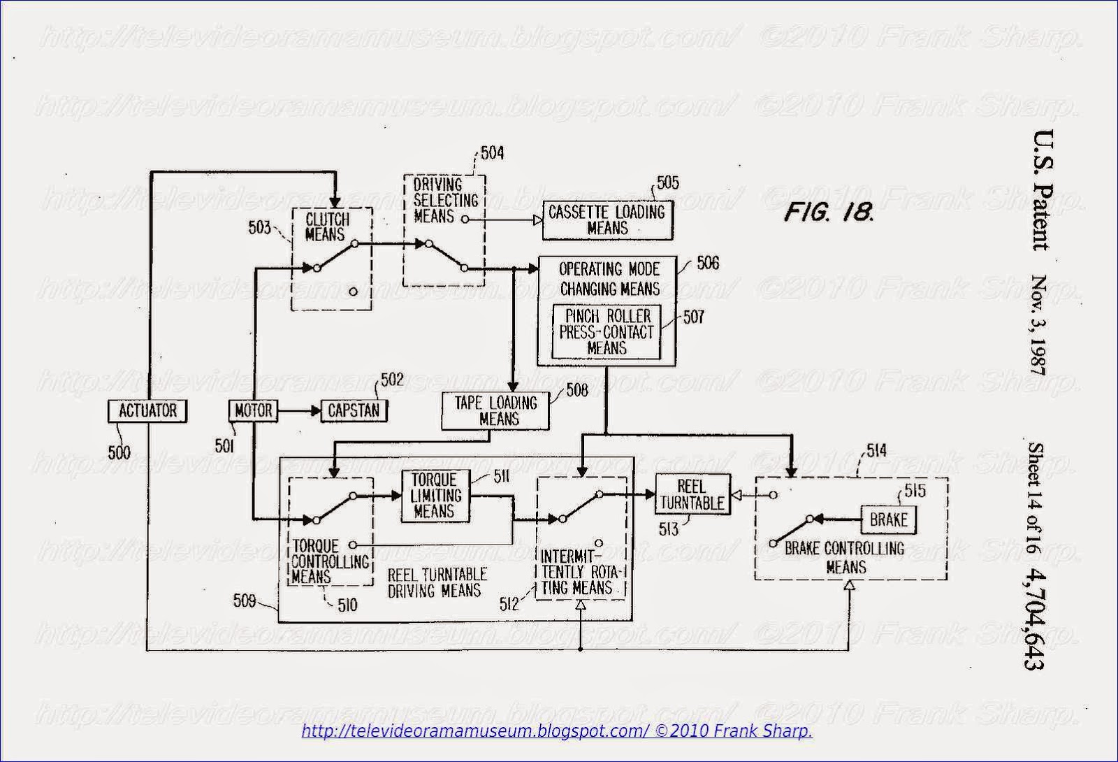
FIG. 18 is a block diagram of the apparatus in the state just before the recording/reproducing mode.
FIG. 19 is a schematic plan view of the apparatus in the state just before the recording/reproducing mode.
FIG. 20 is a block diagram of the apparatus in the recording/reproducing mode.
DESCRIPTION OF THE PREFERRED EMBODIMENT
FIGS. 1, 14, 15, 18 and 20 are block diagrams of an embodiment of the
invention, in which lines connecting respective means and components
show channels for transmitting the rotational driving force of a motor
501, operation of an actuator 500 or operations of respective means to
respective means, thick lines showing the state of the rotational
driving force being transmited and/or the operations, thin lines showing
the states of being inactivated, and arrows showing the directions of
the respective transmissions.
As explanatio

n will be given of the basic construction of the embodiment
of the invention using FIG. 1. The rotational driving force of the
motor 501 which drives a capstan 502 is transmitted intermittently to a
driving selecting means 504 by a clutch means 503. The driving selecting
means 504 selectively drives either a cassette loading means 505, or an
operating mode changing means 506 and a tape loading means 508. The
operating mode changing means 506 working with the tape loading means
508 comprises a pinch roller press-contact means 507 and controls both
an intermittently rotating means 512 and a brake controlling means 514
having a brake 515. A reel turntable driving means 509 transmitting the
rotational driving force of the motor 501 to a reel turntable 513 has a
torque controlling means 510 controlled by the tape loading means 508, a
torque limiting means 511 and the intermittently rotating means 512.
The torque controlling means 510 transmits the rotational driving force
of the motor 501 to the intermittently rotating means directly or
indirectly through the torque limiting means 511 under the control of
the tape loading means 508. The reel turntable 513 is intermittently
supplied with the rotational driving force of the motor 501 by the
intermittently rotating means 512 and is selectively braked by the brake
controlling means 514. The actuator 500 drives and/or controls the
clutch means 503, the intermittently rotating means 512 and the brake
controlling means 514.
FIG. 2 is a plan view of the embodiment of the invention, i

n which a
supply reel turntable 4 and a take-up reel turntable 5 are fitted
freely-rotatably onto shafts 2 and 3 mounted on a chassis 1 and engage
with a supply reel hub 7 and a take-up reel hub 8 respectively within a
tape cassette 6 mounted at a predetermined position (shown in dot-dash
lines) of the apparatus, thereby rotating integrally with the reel hubs 7
and 8. Within the tape cassette 6 which is provided at its front with
three recesses 10, 11 and 12, the magnetic tape 9 drawn out of the
supply reel hub 7 passes by the front surface of the tape cassette 6 and
reaches the tape-up reel hub 8. Tape guide posts 13, 14 secured on
supports 13b and 14b respectively, and a tape guide post 15 for drawing
the magnetic tape 9 out of the tape cassette 6 and guiding the magnetic
tape 9, are within the respective recesses 10, 11 and 12 and behind the
magnetic tape 9.
FIGS. 2, 16, 17 and
19 are plan views of the embodiment of the
invention, in which a guide drum 16 having rotary magnetic heads (not
shown), a fixed post 17 guiding the magnetic tape 9, a full track erase
head 19 erasing all signals recorded on the magnetic tape 9, an audio
erase head 20 erasing audio signals recorded on the magnetic tape 9, an
audio & control head 21 recording and/or reproducing audio signals
and control signals for controlling a tape speed and phase on/from the
magnetic tape 9, a capstan 23 transporting the magnetic tape 9 at a
constant speed in cooperation with a pinch roller 22, and a motor 24
driving the capstan 23 are disposed on the chassis 1. The motor 24 is a
brushless motor with less torque variation and its spindle serves for
the capstan 23.
An explanation will be given of the reel turntable driving means.
Referring to FIG. 2, a pulley 28 having toothed portions 26 and 27 is
fitted rotatably onto a shaft 25 mounted on the chassis 1, and is
rotatably driven by the motor 24 through a belt 29 stretched around the
pulley 28 and a pulley 24a press-fitted onto the capstan 23. Also a
support plate 30 for changing the reduction ratio between the motor 24
and both of the reel turntables 4 and 5 is supported rotatably on the
shaft 25 as shown in FIG. 3. A gear 32 used in the recording/reproducing
mode is fitted rotatably onto a shaft 31 mounted at one end of the
support plate 30 and adapted to always engage with the toothed portion
26 integral with the pulley 28, while a gear 34 used in the
fast-forward-winding mode is fitted rotatably onto a shaft 33 mounted at
the other end of the support plate 30 and adapted to always engage with
the toothed portion 27 integral with the pulley 28. A flexible member
35 having at one end a first cam follower 36 is fixed upon the support
plate 30 as shown in FIG. 4. Thus the torque controlling means 510,
which controls the driving torque of the both reel turntables 4 and 5,
comprises the pulley 28, support plate 30, gear 32 and gear 34.
In FIG. 4, the first rotatable disc 37 which drives the tape loading
means 508, is fit

ted rotatably onto a shaft 38 mounted on the chassis 1,
and has at one side a positive cam of grooved cam 37a engageable with
the first cam follower 36 for driving the torque controlling means 510,
and at the other side a positive cam of grooved cam 37b for driving the
tape loading means 508. The grooved cam 37a and 37b extend at an angle
of 360° or more as shown in FIG. 5B, and the amount of the cam lift
varies between a specific range of degrees of cam rotation. In FIG. 5B,
the symbol "a" shows the curve of the cam lift for the grooved cam 37a,
and the symbol "b" shows the curve of the cam lift for the grooved cam
37b. The first cam follower 36 is adapted to move only in a range of
rotary angle 70° to 120° of the first rotatable disc 37, in which the
first rotatable disc 37 rotates clockwise to move the first cam follower
36 rightwardly in FIG. 2, so that the support plate 30 is swung
clockwise around the shaft 25. A torque limiting member 40 is supported
rotatably on a shaft 39 mounted on the chassis 1 as shown in FIG. 3 and
is adapted to keep the driving torque of the motor 24 transmitted to the
both reel turntables 4 and 5 constant. The torque limiting member 40
comprises an upside gear 41 of the same diameter as the lower part gear
44, fitted rotatably on the shaft 39, the l
ower part gear 44 being
supported rotatably on a boss 43 provided at the upside gear 41, a
friction member 42, such as felt material, adhering to the lower surface
of the upside gear 41, a compression spring 46 pressing the friction
member 42 against an upside gear surface 45, a spring shoe 47, and a
thrust plate 48 and a stopper plate 49. A turnable arm 50 is also
supported rotatably on the shaft 39, and a turnable idler gear 52 always
engageable with the lower part gear 44 is fitted rotatably onto a shaft
51 mounted at one end of the turnable arm 50. A friction member 53,
made of such as a felt material, adheres to the turnable arm 50 and is
disposed between the turnable arm 50 and an upper surface 57 of the
turnable idler gear 52. A spring shoe 55 and a stopper plate 56 are
supported on the shaft 51 and a compression spring 54 is disposed
between the rear surface of the turnable idler gear 52 and the spring
shoe 55 for pressing the friction member 53 against the upper surface 57
of the turnable idler gear 52 as shown in FIG. 3. When the lower part
gear 44 rotates, the turnable arm 50 is turned by the friction between
the upper surface 57 of the turnable idler gear 52 and the friction
member 53 corresponding to the rotational direction of the lower part
gear 44, and allows the turnable idler gear 52 to engage with an idler
gear 59 always engageable with a reel gear 58 integral with the take-up
reel turntable 5 or an i
dler gear 61 always engageable with a reel gear
60 integral with the supply reel turntable 4, thereby selectively
transmitting the rotation of the motor 24 to the take-up reel turntable 5
or the supply reel turntable 4.
In accordance with the rotation of the first rotatable disc 37 from 0°
to 70°, the gear 34 engageable with the toothed portion 27 integral with
the pulley 28 engages with the lower part gear 44 so that the driving
torque of the motor 24 is directly transmitted to the both reel
turntables 4 and 5 but not through the friction member 42 of the torque
limiting member 40. As stated above, in accordance with the rotation of
the first rotatable disc 37 from 70° to 120°, the support plate 30 turns
clockwise around the shaft 25 to disengage the gear 34 from the lower
part gear 44, and then allows the gear 32 which engages with the toothed
portion 26 integral with the pulley 28 to engage with the upside gear
41, so that after rotation of more than 120°, the gear 32 engages with
the upside gear 41. Furthermore the reduction ratio of the gear train
consisting of the toothed portion 26, the gear 32 and the upside gear 41
is larger than that of the gear train consisting of the toothed portion
27, the gear 34 and the lower part gear 44. Hence, the torque
controlling means 510 is driven and controlled by the first rotatable
disc 37 which drives the tape loading means 508 to be discussed below.
The reduction ratio from the upside gear 41 to the reel gear 60 integral
with the supply reel turntable 4 is larger than that from the upside
gear 41 to the reel gear 58 integral with the take-up reel turntable 5,
so as to make the winding torque of the supply reel turntable 4 in the
reviewing mode larger than that of the take-up reel turntable 5 in the
recording and/or reproducing mode.
Next, an explanation will be given of the actuator 500 and the clutch means 503.

The rotational driving force of the motor 24 (501 in FIG. 1) is
transmitted to the first rotatable disc 37, the second rotatable disc 66
and the third rotatable disc 67 respectively through a first idler gear
62 engageable with the toothed portion 27 integral with the pulley 28, a
second idler gear 63 engageable with the first idler gear 62, and the
clutch gear 65 engageable with both the second idler gear 63 and a first
toothed portion 64a integral with a driving gear 64. The clutch gear 65
is always engageable with the second idler gear 63 and is supported
rotatably on a shaft 68 mounted on the chassis 1, is allowed to move
upwardly and downwardly along the shaft 68, is always biased downwardly
by a compression spring 65a, and is disposed on a first clutch plate 69
fitted rotatably onto a shaft 70 mounted on the chassis 1 as shown in
FIGS. 6A and 6B. The first clutch plate 69 has an upper face 69a and a
lower face 69b which are different in height as shown in FIGS. 6A, 6B
and 7. A slot 72 provided in a second clutch plate 71 which is fitted
rotatably onto the shaft 70 and disposed on the first clutch plate 69,
engages with a projection 73 provided on the first clutch plate 69, and a
torsion spring 75 is disposed between the projection 73 and a
projection 74 provided on the second clutch plate 71 as shown in FIG. 7,
so that the second clutch plate 71 is always biased counterclockwise,
as shown in FIG. 2, to cause the first clutch plate 69 and the second
clutch plate 71 to turn integrally with each other around the shaft 70. A
slot 78 provided at one end of a turnable lever 77 supported turnably
on a shaft 76 mounted on the chassis 1 engages with a pin 79 pr

ovided at
one end of the second clutch plate 71, and a slot 80 provided at the
other end of the turnable lever 77 engages with a connecting pin 83
provided on a plunger 82 being supported freely-slidably on a solenoid
81 disposed on the chassis 1 as shown in FIGS. 2 and 8. When the
solenoid 81 is energized, the plunger 82 is retracted in the direction
of the arrow A in FIG. 2 and the turnable lever 77 is turned
counter-clockwise around the shaft 76, instantaneously the second clutch
plate 71 and the first clutch plate 69 are turned clockwise integrally
with each other around the shaft 70 through the torsion spring 75.
Hence, the clutch gear 65 runs onto the upper face 69a from the lower
face 69b of

the first clutch plate 69 and is changed from the condition
as shown in FIG. 6A to that as shown in FIG. 6B, so that the clutch gear
65 engages with the first toothed portion 64a integral with the driving
gear 64. As stated above, the clutch means 503 is driven and controlled
by the actuator 500 comprising the plunger 82 and the solenoid 81.
In the embodiment of the present invention, the actuator 500 comprises
the plunger 82 and the solenoid 81, but it may comprise a motor for
obtaining the same effect in this invention.
When the clutch gear 65 does not engage with the first toothed portion
64a due to the abutting of the surfaces of teeth of the clutch gear 65
against that of the first toothed portion 64a regardless of the clutch
gear 65 being moved upwardly in FIG. 6 along the shaft 68 by the first
clutch plate 69, the first clutch plate 69 stops turning while the
second clutch plate 71 turns clockwise around the shaft 70 against the
biasing force of the torsion spring 75. And when the clutch gear 65
engages with the first toothed portion 64a, the first clutch plate 6
starts to turn clockwise again around the shaft 70, and the clu
tch gear
65 runs completely onto the upper face 69a of the first clutch plate 69.
Thus even when the surface of the teeth of the clutch gear 65 abut
against that of the first toothed portion 64a, the plunger 82 and the
turnable lever 77 do not stop turning and the clutch gear 65 is not
subjected to an axial excessive force by the plunger 82.
The driving selecting means 504 which drives selectively either the
cassette loading means 505 or the operating mode changing means 506
comprises a differential gear mechanism 200 as shown in FIG. 6. An
explanation will be given on the differential gear mechanism 200.
The driving gear 64 having the first toothed portion 64a selectively
engageable with the clutch gear 65 and a sun gear 64b are fitted freely
rotatably onto a shaft 84 mounted on the chassis 1. A plurality of
shafts 86 are provided on a retainer gear 85 which is fitted rotatably
onto a boss 64c provided on the driving gear 64, and support rotatably
the planetary gears 87 on the shafts 86, the planetary gears 87 engaging
with the sun gear 64b. And a transmission gear 88 having at the inner
peri
phery an internal toothed portion 88a and at the outer periphery an
external toothed portion 88b is fitted rotatably onto the shaft 84, the
internal toothed portion 88a engaging with the planetary gears 87.
Hence, when the transmission gear 88 is restrained from rotating, the
planetary gears 87 are revolved on their axes round the shaft 84 by the
rotation of the driving gear 64, the retainer gear 85 being decelerated
and rotating around the shaft 84 in the same direction as that of the
driving gear 64. When the retainer gear 85 is restrained from rotating,
the planetary gears 87 are revolved on their axes by the rotation of the
driving gear 64, the transmission gear 88 being decelerated and
rotating around the shaft 84 in the reverse direction to that of the
driving gear 64.
The following explanation will be given of the tape loading means 508.
The first rotatable disc 37 for driving the tape loading means 508
engages with the retainer gear 85. A second cam follower 91 fixed at one
end of an arm 90 supported rotatably on a shaft 89 mounted on the
chassis 1 engages with the grooved cam 37b at the rear surface of the
first rotatable disc 37 as shown in FIGS. 2 and 9. A sector gear 92
formed on the other end of the arm 90 engages with a first loading gear
94 fitted rotatably onto a shaft 93 mounted on the chassis 1. A second
loading gear 95 integral with the first loading gear 94 and rotatable
around the shaft 93 engages with a third loading gear 97 fitted onto a
shaft 96 mounted on the chassis 1. Thus the loading gear train
comprising 94, 95 and 97 rotates in synchronism with the sector gear 92.
In FIG. 9, a first arm 98 for rightward loading is fitted rotatably
onto the shaft 93. A tension spring 99a is stretched between a spring
seat 98a provided at the first arm 98 for rightward loading and a pin
95a mounted on the second loading gear 95, so that the pin

95a abuts
against a stopper 98b provided on the first arm 98 to allow the first
arm 98 and the second loading gear 95 to rotate integrally with each
other. A second arm 101 for rightward loading is connected rotatably at
one end to the end of the first arm 98 through a pin 100 and has a bore
102 at the other end, the bore 102 being engageable with a pin 14a
mounted on the support 14b. Reference numeral 103 designates a first arm
for leftward loading, which has the same construction with respect to
the third loading gear 97 as between the first arm 98 for rightward
loading and the second loading gear 95, thus being integral with the
third loading gear 97 through a tension spring 99b (not shown). The arm
103 also connects at one end rotatably with a second arm 105 for
leftward loading though a pin 104, and has a bore 106 at the other end
of the second arm 105, the bore 106 being engageable with a pin 13a
mounted on the support 13b.
When the first rotatable disc 37 starts to rotate clockwise from the
position in FIG. 2, the second cam follower 91 is not moved during the
clockwise rotation of the first rotatable disc 37 from 0° to 150° as
shown in the curve "b" in FIG. 5B, but after more than 150°, the sector
gear 92 begins to rotate clockwise around the shaft 89 because the
second cam follower 91 is moved leftwardly in FIG. 2. Hence, the first
loading gear 94 engageable with the sector gear 92, the second loading
gear 95 and the first arm 98 for rightward loading rotate
counter-clockwise, and the third loading gear 97 and the first arm 103
for leftward loading rotate clockwise, resulting in that the supports
14b and 13b start movement along guide grooves 108 and 109 provided in
the sub-chassis 107 which is spaced from the chassis 1 by a
predetermined interval and disposed on the chassis 1. When the first
rotatable disc 37 rotates to an angle of 280°, the first arm 98 for
rightward loading and the first arm 103 for leftward loading move the
supports 14b and 13b to the positions where the tape guide posts 14 and
13 thereof abut against the positioning members 110 and 111 respectively
fixed on the sub-chassis 107. Upon more than 280° of the first
rotatable disc 37 rotation, because the tape guide posts 14 and 13 abut
against the positioning members 110 and 111 respectively, the first arm
98 for rightward loading and the first arm 103 for leftward loading
cannot turn further. As a result, the second loading gear 95 and the
third loading gear 97 continue to rotate counter-clockwise and clockwise
against the tension springs 99a and 99b respectively. When the first
rotatable disc 37 rotates beyond an angle of 300°, the sector gear 92,
the second loading gear 95, and the third loading gear 97 do not rotate
because the second cam follower 91 is not moved as shown in the curve
"b" in FIG. 5B.
Next an explanation will be given of the operating mode changing means
506 which drives the pinch roller press-contact means 507, the brake
controlling means 514 and the intermittently rotating means 512.
In FIG. 6, the second rotatable disc 6b engageable with the retainer
gear 85 is fitted freely-rotatably onto a shaft 112 mounted on the
chassis 1 and has at one side a positive cam groove 113 extending
through an angle of 360° or more as shown in FIG. 5A for changing the
operation mode of the apparatus. A cam follower 116 fixed at one end of a
turnable arm 115 which is supported rotatably onto a shaft 114 mounted
on the chassis 1 as shown FIG. 2, engages with the cam grooved 113. The
cam groove 113 is adapted to move the cam follower 116 only in a range
w
here the lifting amount changes as shown in FIG. 5A. The second
rotatable disc 66 has the same diameter and the same number of teeth as
the first rotatable disc 37. A pin 117 fixed at the other end of the
turnable arm 115 engages with a slot 119 provided at one end of a main
rod 118 which moves to a plurality of positions in synchronism with the
movement of the cam follower 116. Guide slots 122 and 123 which are cut
in the main rod 118 are fitted onto the guide shafts 120 and 121
respectively mounted on the chassis 1, and the main rod 118 is mounted
movably for reciprocation along the guide slots 122 and 123. Hence, when
the turnable arm 115 is turned around the shaft 114 by the cam
follower, the main rod 118 is driven in the left or right direction in
FIG. 2 under the guidance of guide shafts 120 and 121 and guide slots
122 and 123. Thus the operating mode changing means 506 comprises the
cam groove 113 and the main rod 118.
A pin 77a fixed at another end of the turnable lever 77 engages with a
slot 130b provided at one end of a sub-rod 130. Guide slots 196 and 197
which are cut in the sub-rod 130 are fitted onto the guide shafts 194
and 195 respectively mounted on the chassis 1, and the sub-rod 130 is
mounted movably for reciprocation alo
ng the guide slots 196 and 197. A
tension spring 199 is stretched between a bore 130c provided at the
other end of the sub-rod 130 and a shaft 198 mounted on the chassis 1,
so that the sub-rod 130 is always biased leftwardly in FIG. 2 by the
tension spring 199. Hence, when the plunger 82 is retracted in the
direction of the arrow A in FIG. 2 by the solenoid 81 being energized,
the turnable lever 77 is turned counter-clockwise around the shaft 76
and the sub-rod 130 is moved rightwardly in FIG. 2. When the solenoid 81
is de-energized, the sub-rod 130 is moved leftwardly in FIG. 2 by the
tension force of the tension spring 199 and the turnable lever 77 is
turned clockwise around the shaft 76, the plunger 82 being moved in the
reverse direction to the arrow A in FIG. 2. Thus the operation of the
plunger 82 is transmitted to the intermittently rotating means 512 and
the controlling brake means 514 to be discussed below by the turnable
lever 77 and the sub-rod 130.
Next an explanation will be given of the brake controlling means 514.
A brake 184 at the take-up reel side and that 185 at the supply reel
side are fitted rotatably onto the shafts 182 and 183 respectively as
shown in FIGS. 2 and 8. A pin 184a fixed at one end of the brake 184
engages with a slot 187a provided at one end of a brake lever 187 which
is fitted rotatably onto a shaft 186 mounted on the chassis 1, whereby
the brake 184 at the take-up reel side is adapted to be actuated by the
brake lever 187. A tension spring 189 is stretched between a pin 187b
fixed at the other end of the brake lever 187 and a pin 188 fixed on the
sub-rod 130, whereby the brake lever 187 is biased counter-clockwise by
the tension spring 189 so that the brake 184 is biased clockwise as
shown in FIG. 2. A tension spring 191 is stretched between a pin 185a
fixed at one end of the brake 185 at the supply reel side and a pin 190
fixed on the sub-rod 130, whereby the brake 185 is biased
counter-
clockwise by the tension spring 191. The brakes 184 and 185,
having brake shoes 184b and 185b which abut against the reel turntables 5
and 4 respectively, are made of flexible material thereby being adapted
to adjust the braking effect when the brake shoes 184b and 185b tend to
bite the reel turntables 5 and 4 respectively. Reference numerals 192
and 193 designate kick pins mounted on the brake lever 187 and the
supply reel side brake 185 respectively. The brakes 184 and 185 are
moved away from the both reel turntables 5 and 4 to release the braking
effect, the kick pins 192 and 193 being pushed leftwardly in FIG. 2 by
the main rod 118, or the pins 187b and 185a being pushed leftwardly by
the sub-rod 130.
The intermittently rotating means 512 which transmits the rotational
driving force of the motor 24 intermittently to both reel turntables 4
and 5 selectively, comprises a rightha
nd stopper arm 126 and a lefthand
stopper arm 127 fitted rotatably onto shafts 124 and 125 respectively
mounted on the chassis 1. A tension spring 133 is stretched between a
pin 128 mounted on the righthand stopper arm 126 and a pin 131 mounted
on the sub-rod 130, the pin 128 abutting against a notch edge surface
130a provided on the sub-rod 130 to restrain the stopper arm 126 from
turning counter-clockwise around the shaft 124. A tension spring 134 is
stretched likewise between a pin 129 mounted on the lefthand stopper arm
127 and a pin 132 mounted on the sub-rod 130, the pin 129 abutting
against a notch edge surface 118a provided on the main rod 118 and/or a
notch edge surface 130d provided on the sub-rod 130 to restrain the
stopper arm 127 from turning clockwise around the shaft 125.
When the conditions are changed from energizing the solenoid 81 as shown
in FIG. 2 to de-energizing the solenoid 81 as shown in FIG. 16 at a
rotary a

ngle of 20° of the second rotatable disc 66 which drives the
operating mode changing means 506, the sub-rod 130 is moved leftwardly
in FIG. 2 by the tension force of the tension spring 199, and the pins
187b and 185a are pushed leftwardly in FIG. 2 by the notch edge surfaces
130e and 130f respectively which are cut in the sub-rod 130, so that
the brakes 184 and 185 are moved away from the both reel turntables 5
and 4 to release the braking effect. At this time, the pins 128 and 129
are pushed leftwardly by the notch edge surfaces 130a and 130d
respectively, and the both stopper arms 126 and 127 are turned clockwise
and counter-clockwise around the shafts 124 and 125 respectively, so
that the turnable idler gear 52 is able to engage rotatably either with
the idler gear 59 or 61. When the conditions are changed from
de-energizing the solenoid 81 as shown in FIG. 16 to energizing, the
plunger 82 is retracted in the direction of the arrow A in FIG. 2
instantaneously and the action of the plunger 82 instantaneously returns
the sub-rod 130 to the condition of FIG. 2. Simultaneously the pins
187b and 185a disengage from the notch edge surfaces 130e and 130f
respectively, thereby instantaneously applying the braking effect to the
both reel turntables 5 and 4 by the tension springs 189 and 191
respectively. At this time, the turnable idler gear 52 is disengaged
either from the idler gear 59 or 61 by the two stopper arms 126 and 127.
Hence, the action of the plunger 82 by operating the solenoid 81 drives
and controls both the intermittently rotating means 512 and the
controlling brake means 514.
When the solenoid 81 is energized and the two stopper arms 126 and 127
are positioned as shown in FIG. 2, the turnable idler gear 52 does not
engage rotatably either with the idler gear 59 or 61 regardless of the
turnable arm 50 being driven by the motor 24 which transmits its
rotation to the turnable arm 50, and the turnable arm 50 turning
clockwise or counter-clockwise around the shaft 39, since the shaft 51
mounted on the turnable arm 50 abuts against the edge surface 126a of
the righthand stopper arm 126 or the edge of 127a of the lefthand
stopper arm 127a. Hence, the two reel turntables 5 and 4 do not rotate.
When the second rotatable disc 66 rotates clockwise to an angle of 110°
as shown in FIG. 4A when the solenoid 81 is energized, the cam follower
116 is not moved and the main rod 118 is not moved either, whereby the
both stopper arms 126 and 127 restrain the turnable arm 50 from turning
as stated above. When the second rotatable disc 66 rotates clockwise
more than an angle of 110° as shown in FIG. 4A in the condition of the
solenoid 81 energized, the cam follower 116 is started to move
rightwardly in FIG. 2,
and the turnable arm 115 is also started to turn
clockwise around the shaft 114, whereby the main rod 118 which engages
with the turnable arm 115 is started to move straight leftwardly in FIG.
2. At this time, the kick pins 192 and 193 are pushed leftwardly by the
notch edge surfaces 118d and 118f respectively, thereby turning
clockwise around the shafts 186 and 183 against the biasing force of the
tension springs 189 and 191. Hence, the brake lever 187 turns clockwise
around the shafts 186, and the brake 184 at the take-up reel side which
engages with the brake lever 187 turns counter-clockwise around the
shaft 182,
the brake 185 at the supply reel side turning clockwise
around the shaft 183. Furthermore, the kick pins 192 and 193 continue to
turn clockwise until the kick pins 192 and 193 run into the edge
surfaces 118e and 118g respectively which moves the brakes 184 and 185
away from the reel turntables 5 and 4 and where the brake effect is
released. After the kick pins 192 and 193 have run onto the edge
surfaces 118e and 118g, the pins 187b and 185f move away from the notch
edge surfaces 130e and 130f of the sub-rod 130 respectively, and the
pins 187b and 185a do not abut against the sub-rod 130 regardless of the
rightward or leftward movement of the sub-rod 130, so that the pins
187b and 185a disengage from the sub-rod 130. Thus the movement of the
plunger 82 is transmitted to neither the brakes 184 and 185 nor the
intermittently rotating means 512. This condition is kept until a rotary
angle of the second rotatable disc 66 becomes 440°. When the second
rotatable disc 66 rotates clockwise to an angle of 150°, the pin 129
which abuts against the notch edge surface 118a of the main rod 118 is
pushed leftwardly in FIG. 2 by the notch edge surface 118a, thereby
turning counter-clockwise around the shaft 125 against the biasing force
of the tension spring 134. Furthermore, the pin 129 continues to turn
counter-clockwise until the pin 129 runs onto the notch edge surface
118b where the turnable idler gear 52 is engageable with the idler gear
61. After the pin 129 which has run into the notch edge surface 118b,
the pin 129 moves slidably onto the notch edge surface 118b, and the
lefthand stopper arm 127 does not further turn in spite of the leftward
movement of the main rod 118, so that the biasing force of the tension
spring 134 does not increase with the movement of the main rod 118. If
the turnable arm 50 turns clockwise at that time, the turnable idler
gear 52 engages with the idler gear 61 as stated above, and the take-up
reel turntable 5 is also capable, of rotating. This condition is kept
until the rotary angle of the second rotatable disc 66 becomes 298°.
When the second rotatable disc 66 rotates from an angle of 298° to 323°,
the cam follower 116 is further moved rightwardly in FIG. 2, and
the
turnable arm 115 is also turned clockwise around the shaft 114, whereby
the main rod 118 is moved straight leftwardly. When the second rotatable
disc 66 rotates to an angle of 313°, the pin 126b mounted on the
righthand stopper arm 126 abuts against the notch edge surface 118c
provided on the main rod 118 thereby being pushed by the notch edge
surface 118c with the leftward movement of the main rod 118. Hence the
pin 126b turns clockwise around the shaft 124 against the biasing force
of the tension spring 133 and continues to turn until the turnable idler
gear 52 is engageable with the idler gear 59. In other words the
rotatable disc 66 rotates to an angle of 323°. When the second rotatable
disc 66 rotates more than an angle of 323°, the turnable idler gear 52
is engageable with the idler gear 59. If the turnable arm 50 turns
counter-clockwise at that time, the turnable idler gear 52 engages with
the idler gear 59, and the take-up reel turntable 5 is capable of
rotating and winding the magnetic tape 9 onto the take-up reel hub 8.
Thus the operating mode changing means 506 which comprises the grooved
cam 113 and the main rod 118, drives and controls both the
intermittently rotating means 512 and the brakes 184 and 185.
Next an explanation will be given of the pinch roller press-contact means 507 in FIGS. 10 and 11.

A gear 135 in engagement with the second rotatable disc 66 driving the
operating mode changing means 506 is fitted rotatably onto a shaft 136
mounted on the chassis 1 and engages with a toothed portion 139 integral
with a driving member 138 which is fitted rotatably onto a shaft 137
mounted on the chassis 1. The driving member 138 is provided with a
first peripheral cam 140, a cylindrical cam 141 and a second peripheral
cam 142. The first peripheral cam 140 abuts against a first edge surface
144a of a relay lever 144 which is fitted rotatably onto a shaft 143
mounted on the chassis 1, so that the first peripheral cam 140 pushes
the first edge surface 144a. The cylindrical cam 141 abuts against a
projection 145a of a guide member 145 which is fitted onto the shaft
137, guided by the shaft 137 and capable of moving perpendicularly to
the chassis 1, thereby moving the guide member 145 up and down. The
second peripheral cam 142 abuts against a projection 146a of a pressure
lever 146 which presses the pinch roller 22 to be in contact with the
capstan 23 afte
r the pinch roller 22 has moved to a predetermined
position, so that the second peripheral cam 142 pushes the projection
146a. The outer periphery 148 a of a pinch roller arm 148 which is
fitted rotatably onto the shaft 143 is fitted both into the interior
146b of the pressure lever 146 and into a bore 145b provided at one end
of the guide member 145, and the pinch roller arm 148 is supported by an
upper surface 146c of the pressure lever 146, the pressure lever 146
being supported by the upper surface 145c of the guide member 145. Hence
the pressure lever 146 and the pinch roller arm 148 move integrally
with the guide member 145 upwardly or downwardly in FIGS. 10 and 11
guided by the shaft 143, when the guide member 145 moves upwardly or
downwardly guided by the shaft 137. A tension spring 151, as shown in
FIG. 2, is stretched between a hook 149 provided on the pressure lever
146 and a hook 150 provided on the pinch roller arm 148, so that the
edge surface 148 of the pitch roller arm 148 abuts against a stopper
146d provided on the pressure lever 146 to cause the pressure lever 146
and the pinch roller arm 148 to rotate integrally with each other. The
projection 146a on the pressure lever 146 is always pushed by a biasing
spring (not shown) at the outer periphery of the driving member 138, and
to the se
cond peripheral cam 142 after the guide member 145 has moved
down to the lowest position, the pressure lever 146 turning around the
shaft 143 by the action of the second peripheral cam 142. The pinch
roller 22 is fitted freely-rotatably onto a shaft 152 mounted at one end
of the pinch roller arm 148 rotating integrally with the pressure lever
146. On the other hand, the tape guide post 15 for drawing the magnetic
tape 9 out of the tape cassette 6 is fixed at one end of a guide post
arm 154 fitted rotatably onto a shaft 153 mounted on the chassis 1, a
pin 155 being fixed at the other end of the guide post arm 154 so as to
abut against a second edge surface 144b of the relay lever 144. The pin
155 is pushed by the second edge surface 144b of the relay lever 144, so
that the guide post arm 154 turns around the shaft 153. The cylindrical
cam 141, the first peripheral cam 140 and the second peripheral cam
142, as shown in FIG. 5C, are adapted to vary the amounts of cam lift
between a specific range of degrees of cam rotation and symbols "a", "b"
and "c" show the curves of cam lift for the cylindrical cam 141, the
first peripheral cam 140 and the second peripheral cam 142 respectively.
The horizontal axis in FIG. 5C shows the rotary angle of the driving
member 138 and the broken lines in FIGS. 5A, 5B and 5C show
correspondence to a rotary angle of the second rotatable disc 66 which
drives the driving mem
ber 138 increasingly in speed. For instance, when
the second rotatable disc 66 rotates to an angle of 150°, the second
rotatable disc 66 drives the driving member 138 rotatably to an angle of
244°.
The clockwise rotation of the second rotatable disc 66 is transmitted to
the driving member 138 through the gear 135, so that the driving member
138 rotates clockwise. When the driving member 138 rotates to an angle
of 277°, the first edge surface 144a of the relay lever 144 is pushed by
the first peripheral cam 140 and the relay lever 144 rotates
counter-clockwise around the shaft 143, at which time the second edge
surface 144b of the relay lever 144 pushes the pin 155 and the guide
post arm 154 rotates clockwise around the shaft 153. The tape guide post
15 fixed on the guide post arm 154 draws out the magnetic tape 9 to a
predetermined position as shown in FIG. 17, so that the magnetic tape 9
forms a tape path as shown in dot-dash lines in FIG. 17, and the tape
guide post 15 is locked by locking means (not shown). When the driving
member 138 continues its rotation to an angle of 527° as shown in FIG.
5C, the guide member 145 abutting against the cylindrical cam 141, the
pressure lever 146 and the pinch roller arm 148 move down integrally
with each other perpendicularly to the tape path of the magnetic tape 9
along the shaft 143 guided by the cylindrical cam 141, and the pinch
roller 22 also moves down perpendicularly to the tape path of the
magnetic tape 9 as shown in FIG. 11


from the position where the tape
guide post 15 is not hindered from drawing out the magnetic tape 9 as
shown in FIG. 10, so as to be positioned inside of the loop of the tape
path formed by the tape guide post 15 drawing out the magnetic tape 9 as
shown in dot-dash lines in FIG. 17.
Furthermore when the driving member 138 continues its rotation and the
projection 146a of the pressure lever 146 is pushed by the second
peripheral cam 142, the pressure lever 146 and the pinch roller arm 148
turn clockwise integrally around the shaft 143, so that the pinch roller
22 abuts against the capstan 23 by the time when the rotary angle of
the driving member 138 becomes 587°, whereby the pinch roller arm 148 is
restrained from turning. After that, only the pressure lever 146 turns
continuously and the hook 149 of the pressure lever 146 moves away from
the hook 150 of the pinch roller arm 148 against the biasing force of
the tension spring 151. When the driving member rotates to an angle of
587°, the pinch roller 22 is brought into press-contact with the capstan
23 at the predetermined strength. Even wh
en the driving member 138
turns further over an angle of 587°, the amount of cam lift of the
second peripheral cam 142 remains unchanged as shown in the curve "c" in
FIG. 5C and the pinch roller 22 remains in press-contact with the
capstan 23. Hence the magnetic tape 9 is transported at a constant speed
by cooperation of the pinch roller 22 with the capstan 23 which is
driven rotatably directly by the brushless motor 24 rotating.
Next an explanation will be given of the driving selecting means 504.
In FIGS. 12A, 12B and 6A, the second rotatable disc 66 which drives the
operating mode changing means 506 and the tape loading means 508, and
the third rotatable disc 67 which drives the cassette loading means 505
are both fitted rotatably onto the shaft 112 and in engagement with the
retainer gear 85 and the transmission gear 88 respectively. On the outer
peripheries of cylinders 66a and 67a of the second and third rotatable
discs 66 and 67, notched grooves 160 and 161 are provided respectively,
into which projection stoppers 158 and 159 are fit, the stoppers being
provided at both ends of a detent arm 157 fitted rotatably onto a shaft
156 mounted on the chassis 1. When the projection stopper 158 of the
detent arm 157 enters into the notched groove 160 of the second
rotatable disc 66, the projection stopper 159 abuts against
the outer
periphery of cylinder 67a of the third rotatable disc 67. When the
projection stopper 159 enters into the notched groove 161 of the third
rotatable disc 67, the projection stopper 158 abuts against the outer
periphery of cylinder 66a of the second rotatable disc 66. FIG. 12A
shows the condition when the tape cassette 6 is not mounted on the
apparatus, and FIG. 12B shows the condition when the tape cassette 6 in.
When the tape cassette 6 is inserted into the apparatus when it is in
the state shown in FIG. 12A,

the motor 24 rotates counter-clockwise to
transmit its rotation to the driving gear 64. With the driving gear 64
starting its counter-clockwise rotation, the projection stopper 158 of
the detent arm 157 enters into the notched groove 160 so as to restrain
the second rotatable disc 66 from rotating. As a result, the retainer
gear 85 engageable with the second rotatable disc 66 is also restrained
from rotating, and the rotation of the driving gear 64 is transmitted
through planetary gears 87 to the transmission gear 88 which only starts
to rotate clockwise. And the third gear 67 engageable with the
transmission gear 88 rotates counter-clockwise to drive the cassette
loading means 505 to be discussed below. When the mounting of the tape
cassette 6 is completed, the tape cassette 6 is locked by the tape
cassette locking means (not shown), whereby the rotation of the third
rotatable disc 67 is stopped. At this time, the phase of the third
rotatable disc 67 is set up so that the notched groove 161 of the third
rotatable disc 67 is positioned opposite to the projection stopper 159
of the detent arm 157 as shown in FIG. 12B. When the third rotatable
gear 67 is stopped and the transmission gear 88 is restrained from
rotating, the retainer gear 85 starts to rotate counter-clockwise by the
rotation of the driving gear 64, and the second rotatable disc 66 which
engages with the retainer gear 85 starts to rotate clockwise. The
projection stopper 158 moves out of the notched groove 160 by the moment
of the clockwise force around the shaft 156 generated by the rotatable
driving force of the second rotatable disc 66 through the notched groove
160, so that the detent arm 157 starts turning clockwise around the
shaft 156. At this time the projection stopper 159 enters into the
notched groove 161 opposite to the projection stopper 159, whereby the
third rotatable disc 67 is locked. Furthermore, when the driving gear 64
continues its counter-clockwise rotation, the second rotatable disc 66
rotates continuously, and the third rotatable disc 67 which drives the
cassette loading means 505 remains locked by the projection stopper 159.
In this way, changes are made from the cassette loading means 505 to
the operating mode changing means 506 or to the tape loading means 508.
When the second rotatable disc 66 rotates through

an angle of 360°, the
cam follower 116 in engagement with the cam groove 113 of the second
rotatable disc 66 moves rightwardly in FIG. 19 and a detent portion 115a
provided at the end of the turnable arm 115 turns clockwise around the
shaft 114. Since the detent arm 157 is restrained from turning by the
detent portion 115a abutting against a stopper pin 162 fixed on the
detent arm 157 as shown in FIG. 19, it is impossible for the projection
stopper 158 to enter the notched groove 160 even when they are opposite
to each other and the projection stopper 159 moves out of the notched
groove 161.
The driving gear 64 rotates clockwise when the motor 24 reversely
rotates clockwise so that the rotational driving force of the motor 24
is used for changing from the operating mode changing means 506 or the
tape loading means 508 to the cassette loading means 505. The second
rotatable disc 66 rotating counter-clockwise and the cam follower 116
moving leftwardly, a projection stopper 115b provided on the left side
of the turnable arm 115 abuts against a pin 66b fixed on the second
rotatable disc 66 to stop the rotation of the second rotatable disc 66
as shown
in FIG. 2, at which time the projection stopper 158 and the
notched groove 160 are positioned opposite to each other. When the
retainer gear 85 in engagement with the second rotatable disc 66 stops,
the transmission gear 88 starts to rotate counter-clockwise, and the
third rotatable disc 67 starts to rotate clockwise. Hence the projection
stopper 159 moves out of the notched groove 161 by the moment of the
counter-clockwise force around the shaft 156 generated by the rotational
driving force of the third rotatable disc 67 through the notched groove
161, whereby the detent arm 157 starts to turn counter-clockwise, at
which time the projection stopper 158 opposite to the notched groove 160
enters into the notched groove 160 to lock the second rotatable disc
66. Furthermore, when the driving gear 64 continues to rotate clockwise,
the second rotatable disc 66 is kept in the locked condition by the
projection stopper 158 and only the third rotatable disc 67 rotates
continuously, so that only the cassette loading means 505 is driven.
Next an explanation will be given of the cassette loading means 505 in FIG. 13 which shows a side view of this mechanism.
Bosses 164 and 165 provided respectively on the right and left sides of a
cassette holder 163 move slidably along guide grooves 168 and 169
provided respectively in a righthand side plate 166 and a
lefthand side
plate 167 which are disposed upright on either side of the chassis, so
that the cassette holder 163 holding the tape cassette 6 moves to mount
the tape cassette 6 at a predetermined position of the apparatus.
Righthand and lefthand wiper arms 170 and 171 in engagement with the
bosses 164 and 165 respectively turn around shafts 172 and 173
respectively mounted on both side plates 166 and 167, a toothed portion
174 being provided on the outer periphery of the righthand wiper arm
170. The toothed portion 174 engages and rotates with a gear train
consisting of gears 175 and 176 and a worm gear 177. A gear 178 fitted
rotatably onto the same shaft as the worm gear 177 and rotating
integrally with the worm gear 177 is geared through a gear 179 to the
third rotatable disc 67 which also engages with the transmission gear 88
as shown in FIGS. 2 and 6A. When the transmission gear 88 rotates
clockwise and the third gear 67 rotates counter-clockwise, both wiper
arms 170 and 171 are consequently driven rotatably clockwise around
shafts 172 and 173 respectively in FIG. 13. Also, the bosses 164 and 165
in engagement with the wiper arms 170 and 171 move slidably along the
guide grooves 168 and 169 respectively, so that the tape cassette 6 and
the cassette holder 163 move from the position "A" shown in dot-dash
lines to the position of "B" shown in solid lines in FIG. 13. When the
third rotatable disc 67 rotates clockwise, and the tape cassette 6 and
the cassette holder 163 move from the position of "B" to that of "A" in
FIG. 13. When the third rotatable disc 67 changes its rotary direction,
the tape cassette 6 and the cassette holder 163 move in reciprocation
between the position "A" and position "B". The front cover 180 provided
in front of the tape cassette 6 is always biased to be closed by a
spring and a locking member (not shown) inside of the tape cassette 6.
When the tape cassette 6 is inserted into and held by the cassette
holder 163, the front cover 180 is released from its locked condition by
a releasing member (not shown) inside of the cassette holder 163 and
abuts an opener 181 fixed on the chassis 1 as the cassette holder moves
down perpendicularly to open the front cover 180. When the tape cassette
6 is in the position "B" in FIG. 13 which sho
ws the condition in which
it has been mounted, the front cover 180 opens high enough for tape
guide posts 13 and 14 and the tape guide post 15 to draw out the
magnetic tape 9. When the tape cassette 6 has been mounted at the
predetermined position, the tape cassette 6 and the cassette holder 163
are locked by the tape cassette locking means (not shown) using, for
instance, a self-locking of the worm gear 177.
Next an explanation will be given of the operations.
When the tape cassette 6 is inserted to the cassette holder 163 in FIGS.
2 and 13, the motor 24 rotates counter-clockwise with the solenoid 81
energized and the plunger 82 is retracted in the direction of the arrow A
in FIG. 2, so that the turnable lever 77 turns counter-clockwise around
the shaft 76 and the sub-rod 130 moves rightwardly in FIG. 2 against
the tension force of the tension spring 199. With the movement of the
sub-rod 130, the pins 187b and 185a move away from the notched edge
surfaces 130e and 130f respectively, so that the brakes 184 and 185 are
driven by the tension force of the tension springs 189 and 191 and the
brake effect is applied to both reel turntables 5 and 4. The turnable
idler gear 52 is also restrained from engaging rotatably with the idler
gears 59 and 61. Simultaneously with the turnable arm 77 rotating
counter-clockwise around the shaft 76, the first and second clutch
plates 69 and 71 turn clockwise integrally with each other around the
shaft 70, whereby the clutch gear 65 runs onto the upper surface 69a of
the first clutch plate 69 and is changed from the condition as shown in
FIG
. 6A to that as shown in FIG. 6B. When the clutch gear 65 engages
with the driving gear 64 as shown in FIG. 6B, the rotation of the motor
24 is transmitted to the clutch gear 65 and the driving gear 64 in
engagement with the clutch gear 65 through the belt 29, the pulley 28,
the first idler gear 62 and the second idler gear 63. At this time, when
the projection stopper 158 enters into the notched groove 160 and the
second rotatable disc 66 is restrained from rotating, the rotation of
the driving gear 64 is transmitted only to the transmission gear 88, and
the third rotatable disc 67 engageable with the transmission gear 88
rotates counter-clockwise in FIG. 2. As stated above, the rotation of
the third rotatable disc 67 is transmitted to the toothed portion 174
integral with the righthand wiper arm 170 through the gears 179 and 178,
the worm gear 177 and the gears 176 and 175, whereby the righthand
wiper arm 170 rotates clockwise in FIG. 13 and both the tape cassette 6
and the cassette holder 163 are mounted at the predetermined position.
Then the third rotatable disc is stopped from its rotation by the tape
cassette 6 and the cassette holder 163 being locked by the tape cassette
locking means (not shown). In other words, the rotational driving force
of the motor 24 is transmitted to the cassette loading means 505
through the clutch means 503 and the driving selection means 504, and
the plunger 82 drives the intermittently rotating means 512 and the
controlling brake means 514.
Further, when the motor 24 continues its rotation, the projection
stopper 158 moves out of the notching groove 160 and the projection
stopper 159 enters into the notched groove 161, so that the third
rotatable disc 67 is locked and both the first rotatable disc 37 and the
second rotatable disc 66 engageable with the retainer gear 85 start to
rotate clockwise respectively. When the first rotatable disc 37 rotates
to an engle of 20°, the motor 24 stops its rotation and the apparatus is
put into the stopping mode.
When a fast-forward-winding button (not shown) is pushed with the
apparatus in the stopping mode as stated above, the motor 24 starts to
rotate counter-clockwise simultaneously and the solenoid 81 is
de-energized. With the solenoid 81 de-energized, the sub-rod 130 is
moved leftwardly as shown in FIG. 16 by the tension force of the tension
spring 199, and the pins 187b and 185a are respectively pushed
leftwardly in FIG. 16 by the notch edge surfaces 130e and 130f, so that
the brakes 184 and 185 are moved away from the reel turntables 5 and 4
respectively, and the braking effect is released to allow both reel
turntables to rotate.
When the pins 128 and 129 are also pushed leftwardly by the notch edge
surfaces 130a and 130d of the sub-rod 130 respectively, the righthand
stopper arm 126 turns clockwise around the shaft 124 and the lefthan
d
stopper arm 127 turns counter-clockwise around the shaft 125, so that
the turnable idler gear 52 is capable of rotatably engaging with the
idler gear 59 at the take-up reel side. The turnable lever 77 turns
clockwise around the shaft 76, and the clutch plates turn
counter-clockwise integrally with each other around the shaft 70, so
that the clutch gear 65 which is always biased downwardly in FIG. 6 by
the compression spring 65a moves onto the lower face 69b from the upper
face 69a of the first clutch plate 69 thereby being changed from the
condition as shown in FIG. 6B to that as shown in FIG. 6A. As a result,
the clutch gear 65 disengages from the driving gear 64 so that the first
and second rotatable discs 37 and 66 are not driven. The rotation of
the motor 24 is transmitted to the gear 34 through the belt 29 and the
toothed portion 27 of the pulley 28 to cause the gear 34 to rotate
clockwise and the lower part gear 44 to rotate counter-clockwise in FIG.
16. With the rotation of the lower part gear 44, the turnable arm 50
turns counter-clockwise to make the turnable idler gear 52 engageable
with the idler gear 59 at the take-up reel side. Thus the
counter-clockwise rotation of the motor 24 is transmitted to the take-up
reel turntable 5, which rotates clockwise, and the magnetic tape 9 is
wound on the take-up reel hub 8, so that the apparatus is in the
fast-forward-winding mode. In this case the rotational driving force of
the motor 24 is transmitted to the take-up reel turntable directly, not
through the friction member 42 of the limiting torque member 40. In
other words, the rotational driving force of the motor 24 is transmitted
to both reel turntables 4 and 5 through the torque controlling means
510 and the intermittently rotating means 512 which are included in the
reel turntable driving means 509, and the plunger 82 drives and
contro
ls, the clutch means 503, the intermittently rotating means 512
and the brake controlling means 514 as shown in FIG. 15 which is the
block diagram of the apparatus in the fast-forward-winding mode.
Next, the motor stops its rotation and the solenoid 81 is energized,
either when a stopping button is pushed in the fast-forward-winding mode
or when a transparent tape (not shown) attached to the end of the
magnetic tape 9 is optically detected to generate a termination
detecting signal. As stated above, the sub-rod 130 is moved leftwardly
in FIG. 16 instantaneously when the solenoid 81 is energized, and the
notch edge surface 130a of the sub-rod 130 pushes the pin 128 to turn
the righthand stopper arm 126 counter-clockwise. The edge surface 126a
of the righthand stopper arm 126 urges the shaft 51 to turn the turnable
arm 50 counter-clockwise in FIG. 16, so that the turnable idler gear 52
disengages from the idler gear 59 and the take-up reel turntable 5
stops its rotation. The brakes 184 and 185 are driven simultaneously by
the tension force of the tension springs 189 and 191 respectively, and
the brake effect is applied to the both reel turntables 5 and 4
instantaneously. The clutch gear 65 runs onto the upper face 69a from
the lower face 69b of the first clutch plate 69 of which condition is
changed from that in FIG. 6A to that in FIG. 6B, thereby allowing the
clutch gear 65 to engage with the driving gear 64 again as shown in FIG.
6B. Hence the apparatus is placed in the stopping mode as shown in FIG.
14.
The explanation of the operation in the rewinding mode is omitted,
because it is almost the same as that in the fast-forward-winding mode
described above, except that the rotational direction of the motor 24 is
the opposite and that the supply reel turntable 4 is rotatably driven.
Next, when a recording and/or reproducing button (not shown) is pushed
when the apparatus is in a stopping mode, the motor 24 rotates
counter-clockwise with the solenoid 81 still energized. The rotation of
the motor 24 is transmitted through the clutch gear 65 in engagement
with the driving gear 64 and the retainer gear 85 to the first and
second rotatable discs 37 and 66, both of which rotate clockwise in FIG.
17. The rotary angle of the second rotatable disc 66 is the same as
that of the first rotatable disc 37 as shown in FIGS. 5A and 5B, because
the second rotatable disc 66 has the same diameter and number of teeth
as the first rotatable disc 37. When the second rotatable disc 66
rotates through an angle of 110°, the cam follower 116 is moved
rightwardly in FIG. 17 by the cam grove 113 so that the main rod 118 is
moved straight leftwardly in FIG. 17. And the kick pins 192 and 193 are
pushed leftwardly by the notch edge surfaces 118d and 118f respectively,
so that the brakes 184 and 185 move away from the reel turntables 5 and
4 to allow the braking effect to be released. The condition of the
braking effect being released is held until the rotary angle of the
second rotatable disc 66 becomes 440

°. During this time, that condition
is still kept, even if the plunger 82 and the sub-rod 130 are moved by
energizing or de-energizing the solenoid 81. When the first rotatable
disc 37 rotates to an angle of 120° with the rotation of the second
rotatable disc 66, the first cam follower 36 is moved rightwardly in
FIG. 17 by the cam groove 37a and the support plate 30 is turned
clockwise around the shaft 25, whereby the gear 34 disengages from the
lower part gear 44 and the gear 32 engages with the upper gear 41. The
rotation of the upper gcar 41 is transmitted to the lower part gear 44
and the turnable idler gear 52 through the friction member 42 of the
torque limiting member 40. Although the turnable arm 50 turns clockwise
at this time, the take-up reel turntable 5 never rotates because the
turnable idler gear 52 is restrained from engaging with the idler gear
59 at the take-up reel side by the righthand stopper arm 126. When the
second rotatable disc 66 continues to rotate to an angle of 150°, the
cam follower 116 is moved rightwardly in FIG. 17 by the cam groove 113
and the turnable arm 115 is turned clockwise around the shaft 114,
whereby the main rod 118 in engagement with the turnable arm 115 is
moved leftwardly and the lefthand stopper arm 127 turns
counter-cloc
kwise around the shaft 125, so that the turnable idler gear
52 is capable of engaging with the idler gear 61 at the supply reel
side. When the first rotatable disc 37 rotates to an angle of 150°, the
sector gear 92 starts to rotate clockwise in FIG. 17 as stated above,
whereby the tape loading means 508 is driven so that the tape guide
posts 13 and 14 begin to draw the magnetic tape 9 out of the tape
cassette 6. When the first and second rotatable discs 37 and 66 rotate
to an angle of 170°, the driving member 138 rotates to an angle of 277°
as shown in FIG. 5C, whereby the tape guide post 15 draws the magnetic
tape 9, as shown in FIG. 14, out of the tape cassette 6 to the
predetermined position, so that the tape guide post 15 is locked by the
locking means (not shown). When the driving member 138 rotates to an
angle of 277°, the pressure lever 146, the pinch roller arm 148 and the
pinch roller 22 start to move down perpendicularly to the chassis 1,
inside of the loop of the tape path formed by the tape guide post 15
drawing out the magnetic tape 9 as shown in dot-dash lines in FIG. 17.
When the first rotatable disc 37 rotates to an angle of 280°, the tape
guide posts 13 and 14 abut against the positioning members 110 and 111
respectively. When the first rot
atable disc 37 rotates further to an
angle of 300°, the tape guide posts 13 and 14 are brought into
press-contact with the positioning member 110 and 111 with a
predetermined strength. On the other hand, when the second rotatable
gear 66 rotates from an angle of 298° to 323°, the cam follower 116 is
moved further rightwardly, and the main rod 118 is moved leftwardly in
FIG. 19, whereby the righthand stopper arm 126 turns, clockwise and the
turnable idler gear 52 restrained from the engagement with the idler
gear 59 at the take-up reel side is released, so that the turnable idler
gear 52 engages with the idler gear 59 and the magnetic tape 9 is wound
onto the take-up reel hub 8 without slacking by the take-up reel
turntable 5 rotating clockwise. When the first and second rotatable
discs 37 and 66 rotate to an angle of 323°, the driving member 138
rotates to an angle of 527° and the pinch roller 22 is positioned inside
of the loop of the tape path of the magnetic tape 9 as shown in FIG.
11. Furthermore, when the driving member 138 rotates to an angle of
587°, the pinch roller 22 is brought into press-contact with the capstan
23 with a predetermined strength, and the magnetic tape 9 is
transported at a constant speed by cooperation of the pinch roller with
the capstan 23 which is rotatably and directly driven counter-clockwise
by the brushless motor 24. In brief, as shown in FIG. 18, the rotational
driving force of the motor 24 drives the operating mode changing means
506 and the tape loading means 508, and the plunger 82 drives only the
clutch means 503.
When the first and second rotatable discs 37 and 66 rotate to an ang

le
of 370° and the driving member 138 rotates at the same time to an angle
of 604°, the clutch gear 65 disengages from the driving gear 64 when the
solenoid 81 is de-energized, whereby the first rotatable disc 37, the
second rotatable disc 66 and the driving member 138 stop their rotation
and the rotation of the motor 24 is transmitted only to the capstan 23
and the take-up reel turntable 5. Hence the apparatus is placed in the
recording and/or reproducing mode. In this way the magnetic tape 9 is
loaded around the guide drum 16 and on the full track erase head 19, the
audio erase head 20 and the audio & control head 21, and is wound
on the take-up reel hub 8 without being slackened, so that the signals
are recorded and/or reproduced on/from the magnetic tape 9. In brief,
the rotational driving force of the motor 24 is transmitted to the reel
turntable 513 through the torque limiting means 510 as shown in FIG. 20.
Next, when the stopping button is pushed in the recording and/or
reproducing mode, the clutch gear 65 engages with the driving gear 64
and the solenoid 81 is energized as shown in FIG. 19 and the motor 24
rotates in the
reverse direction, from counter-clockwise to clockwise,
so as to rotate the first and second rotatable discs 37 and 66
counter-clockwise. With the counter-clockwise rotation of the second
rotatable disc 66, the cam follower 116 is moved leftwardly and the main
rod 118 is moved rightwardly in FIG. 19. When the first and second
rotatable discs 37 and 66 rotate reversely to an angle of 150° and the
driving member 138 rotates reversely to an angle of 244°, the tape guide
posts 13, 14 and 15 and the pinch roller 22 return respectively to the
positions shown in FIG. 16. The turnable arm 50 turns clockwise with the
motor 24 rotating reversely clockwise and the turnable idler gear 52
engages with the idler gear 61 at the supply reel side, so that the
supply reel turntable 4 rotates counter-clockwise and winds the
discharged magnetic tape 9 onto the supply reel hub 7 without slackening
the magnetic tape 9. When the second rotatable disc 66 rotates
reversely over an angle of 150°, lefthand stopper arm 127 turns
clockwise in FIG. 17 around the shaft 125 thereby disengaging the
turnable idler gear 52 from the idler gear 61 at the supply reel side,
so that the supply reel turntable 4 stops its rotation and the magnetic
tape 9 completes being wound onto the supply reel h
ub 7. The brakes 184
and 185 abut against the reel turntables 5 and 4 respectively when the
second rotatable disc 66 continues its reverse rotation to an angle of
110°, thereby applying the brake effect to the both reel turntables 5
and 4. When the first rotatable disc 37 rotates reversely to an angle of
120°, the support plate 30 turns counter-clockwise around the shaft 25,
thereby disengaging the gear 32 from the upper gear 41 to allow the
gear 34 to engage with the lower part gear 44. When the first and second
rotatable discs 37 and 66 thereafter continue their reverse rotations
to an angle of 20°, a switch (not shown) works to stop the motor 24 and
the apparatus is placed in the stopping mode.
Furthermore, when an ejecting tape cassette button (not shown) is
pushed, the projection stopper 159 moves out of the notched groove 161
of the third rotatable disc 67 and the projection stopper 158 enters
into the notched groove 160 of the second rotatable disc 66, whereby the
first and second rotatable discs 37 and 66 stop their rotations and the
third rotatable disc 67 rotates clockwise in FIG. 2 so that the tape
cassette 6 and the cassette holder 163 move from the position "B" to
position "A" shown in FIG. 13 to eject the tape cassette 6 from the
apparatus.
As seen from the above explanation, the present invention makes it
possible to accomplish with only one motor the tape cassette loading
operation, the tape loading operation, the operating mode changing
operation and the magnetic tape transporting operation. For the above
reason, the number of motors utilized in the apparatus is remarkably
reduced thereby reducing the cost of the apparatus. Also, the apparatus
has a low power consumption and light weight due to th
e use of only one
motor.
The actuator comprises a plunger, so that its operation is quick in
changing from the fast-forward-winding mode or rewinding mode to the
stopping mode and so that it is possible to apply the brake effect
instantaneously. Hence the braking action is so quick and ensured by
detecting the end of the magnetic tape that the trouble of applying,
exessive tension to the magnetic tape when its end is reached is
eliminated.
Since the motor is a brushless motor with less torque variation and its
spindle serves for the capstan, it minimizes the variation in the speed
of the tape and also minimizes wow and flutter in the tape transport.
It must be also noticed that a thin (low profile) MTRR apparatus can be
achieved by freely disposing the motor which drives the capstan directly
at a position where it does not overlap the tape cassette.


 Max Grundig (7
May 1908 – 8 December 1989) was the founder of electronics company
Grundig AG.Max Grundig is one of the leading business personalities of
West German post-war society, one of the men responsible for the German
“Wirtschaftswunder” (post-war economic boom).
Max Grundig (7
May 1908 – 8 December 1989) was the founder of electronics company
Grundig AG.Max Grundig is one of the leading business personalities of
West German post-war society, one of the men responsible for the German
“Wirtschaftswunder” (post-war economic boom).


 Grundig in Belfast
 In
1972, Grundig GmbH became Grundig AG. After this Philips
began to gradually accumulate shares in the company over the
course of many years, and assumed complete control in 1993.
Philips resold Grundig to a Bavarian consortium in 1998 due to
unsatisfactory performance.
In
1972, Grundig GmbH became Grundig AG. After this Philips
began to gradually accumulate shares in the company over the
course of many years, and assumed complete control in 1993.
Philips resold Grundig to a Bavarian consortium in 1998 due to
unsatisfactory performance.

he Second World War, consumer

During the 1970s, this picture of a strong West German

Office may appeal for permission to proceed with their plans to the
unts a very receptive audience at the European Commission, where, by common consent of German participants in the policy-formation process, Philips wields great political influence. By all accounts, Philips‘s pressure was also responsible for the conversion to the protectionist camp of the Dutch Government, which hitherto had been a bastion of free trade philosophy within the EEC. By imposing unilateral import controls through the channelling of imported VCRs through the customs depot at Poitiers (see above), the French Government had already staked out its position on VCR trade with Japan. It presumably
s traditional policy in
The success of the V2000 firms in obtaining any agreement at all
onfessed publicly that if the firm carried on five more
ir deal were exacer-
 it Werkstatt. Bald fabriziert der Betrieb auch
Transformatoren und Spulen, später zudem Prüfgeräte. 1934 zahlt Grundig
den Teilhaber und Freund Karl Wurzer aus. 1938 beträgt der Umsatz mehr
als 1 Mio. RM. Während des Krieges fabriziert Grundig im Dorf Vach mit
etwa 600 Personen, darunter vielen Ukrainerinnen, Kleintrafos,
elektrische Zünder und Steuergeräte für die V-Raketen. Das
Grundig-Vermögen schätzt man am Kriegsende auf 17,5 Mio. RM
it Werkstatt. Bald fabriziert der Betrieb auch
Transformatoren und Spulen, später zudem Prüfgeräte. 1934 zahlt Grundig
den Teilhaber und Freund Karl Wurzer aus. 1938 beträgt der Umsatz mehr
als 1 Mio. RM. Während des Krieges fabriziert Grundig im Dorf Vach mit
etwa 600 Personen, darunter vielen Ukrainerinnen, Kleintrafos,
elektrische Zünder und Steuergeräte für die V-Raketen. Das
Grundig-Vermögen schätzt man am Kriegsende auf 17,5 Mio. RM 


 prising a rotatable
disc having a tape loading cam for driving said tape loading means.
prising a rotatable
disc having a tape loading cam for driving said tape loading means.